Table of Contents
Advertisement
MOVING WATER FORWARD, SINCE 1968
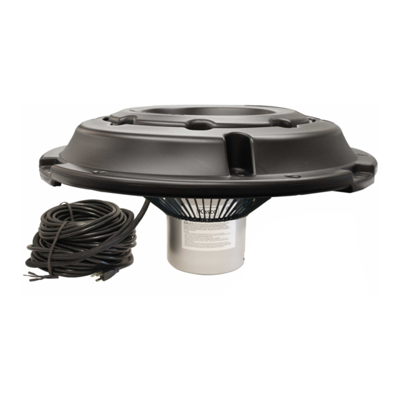
AERATOR &
CIRCULATOR
2400, 3400, 3400H,
4400, 4400H
Operation &
Maintenance
Manual
3020379
ANSI/UL 778: 2016
Ed.6+R:22Feb2017
CSA C22.2 #108: 2014 Ed.5
Document number 884740
Document version 2021.1.1
800 Deere Rd. Prescott, WI 54021 | 715.262.4488 | sales@kascomarine.com | kascomarine.com
1/2HP-1HP AERATOR & CIRCULATOR MANUAL
1
Advertisement
Table of Contents

Subscribe to Our Youtube Channel
Related Manuals for Kasco 2400A


Summary of Contents for Kasco 2400A
- Page 1 MOVING WATER FORWARD, SINCE 1968 AERATOR & CIRCULATOR 2400, 3400, 3400H, 4400, 4400H Operation & Maintenance Manual 3020379 ANSI/UL 778: 2016 Ed.6+R:22Feb2017 CSA C22.2 #108: 2014 Ed.5 Document number 884740 Document version 2021.1.1 800 Deere Rd. Prescott, WI 54021 | 715.262.4488 | sales@kascomarine.com | kascomarine.com 1/2HP-1HP AERATOR &...
-
Page 2: Table Of Contents
TABLE OF CONTENTS Safety First ..........................2 Unit Specifications ........................3 General Instructions .......................3 Parts Included (Aerator) ......................4 Assembly Instructions (Aerator) ...................5 Parts Included (Circulator) .....................8 Assembly Instructions (Circulator) ..................9 Installation Instructions .......................12 Maintenance Recommendations ..................13 Troubleshooting Tips ......................14 Unit Replacement Parts .......................16 Warranty ..........................17 Repair Contact Form ......................19 QUESTIONS? -
Page 3: Safety First
Under NO circumstances should anyone enter the water with the electrical equipment plugged in and/ or in operation. All Kasco equipment is ETL approved to UL and CSA standards for safety in water. How- ever, it is NEVER recommended to enter the water with the equipment in operation. -
Page 4: Unit Specifications
During flotation operation, the water is pulled from 360° around the unit and from below the unit. Following installation, your Kasco aerator or circulator is ready for immediate use. Make sure to keep the motor housing clean from hard wa- ter deposits and/or algae. -
Page 5: Parts Included (Aerator)
Back to Contents PARTS INCLUDED (AERATOR) Item Description Part No. 1/4"-20 x 3-1/2" screw 251210 1/4" split lock washer 840537 1/4", 3/4" OD flat washer 251300 Float 242003 Float retaining clip 222995 Optional Bottom Screen Assembly 3/8"-16 x 2-1/2" hex head screw 820095 3/8"... -
Page 6: Assembly Instructions (Aerator)
Back to Contents ASSEMBLY INSTRUCTIONS (AERATOR) 1. Rest the float (D) on the cage, aligning the power cord to the notch in the float. Align power cord with this notch 2. Locate the bolt holes marked with the indicators. Indicator mark 3. - Page 7 Back to Contents ASSEMBLY INSTRUCTIONS (AERATOR, CONT.) If you are not installing a mesh screen with your bottom screen, continue to step 10. If you are not installing a bottom screen, continue to step 12. 5. Wrap the flat mesh into a cone shape by overlapping both vertical edges by approximately 1 inch and aligning the top and bottom edges of mesh.
- Page 8 Back to Contents ASSEMBLY INSTRUCTIONS (AERATOR, CONT.) 10. Turn the unit upside down and position the bottom screen (H) flush with the float. 11. Fasten the bottom screen to the float using the 3/8"-16 x 2-1/2" screws (F), 3/8" flat washers (G), bottom screen clips (I), and 3/8"-16 nuts (J).
-
Page 9: Parts Included (Circulator)
Back to Contents PARTS INCLUDED (CIRCULATOR) ID Description Qty Part # Horizontal Float 213002 Horizontal Float mounting bracket 993220 Can strap 997174 Tie-down ring 993230 3 mooring ropes 1/4”-20 x 1/2” serrated flange screw 774037 3/8”-16 x 1” serrated flange screw 840533 3/8”-16 serrated flange nut 840532... -
Page 10: Assembly Instructions (Circulator)
Back to Contents ASSEMBLY INSTRUCTIONS (CIRCULATOR) 1. Slide the can strap (C) onto the unit with the flanges directly opposite the cage clamp. The strap should be about 1.5 inches from the cage. 2. Secure the flanges together by fitting a 3/8”-16 x 1” hex head cap screw (H), two 3/8” flat washers (I), and a 3/8”-16 nut (J) in the hole closest to the can. - Page 11 Back to Contents ASSEMBLY INSTRUCTIONS (CIRCULATOR, CONT.) 4. Angle the unit as desired by aligning one of the three the holes in the flanges with the corresponding holes in the brackets. Secure the can strap to the brackets with the 3/8”-16 x 1” serrated flange screw (F) and 3/8”-16 serrated flange nut (G) to fix the unit in one of the angles below.
- Page 12 Back to Contents ASSEMBLY INSTRUCTIONS (CIRCULATOR, CONT.) 6. Secure the tie-down ring (D) to the float using another 1/4”-20 x 1/2” serrated flange screw (E). 7. Attach snap clips (L) to both ends of both chains (K). 8. Use the snap clips to attach the chains to the cage as shown below, evenly spaced on either side of the cage clamp.
-
Page 13: Installation Instructions
Back to Contents INSTALLATION INSTRUCTIONS Use ropes to position the aerator or circulator in the desired location in the pond or lake. Anchor the ropes or secure them to the shoreline so that they are free of slack, but not tight. To prevent twisting of the unit due to motor torque, place the anchor at least 3 feet from the float for each foot of depth. -
Page 14: Maintenance Recommendations
If you have repeat/consistent trips on your ground fault, disconnect the equip- ment and remove it from the water. Inspect the power cord for damage and call Kasco Marine at 715- 262- 4488 for further instructions. -
Page 15: Troubleshooting Tips
A Ground Fault Interrupter (GFI) breaker that trips can indicate an electrical service problem, water contamination in the unit and/or cord, bad breaker, control box problems, motor problems, etc. Try to find out the answers to these questions before you contact Kasco to narrow down the problem. - Page 16 “My aerator or circulator turns itself off and back on without the timer and without tripping the GFI breaker.” (for single phase units only) Each Kasco unit has a thermal overload built in that will turn the unit off when it overheats.
-
Page 17: Unit Replacement Parts
Back to Contents UNIT REPLACEMENT PARTS Description Qty Part # 2400 model propeller 240170 3400 model propeller 340125K 4400 model propeller 440430 Sacrificial anode assembly (1/2” shaft) 243475 Sacrificial anode assembly (5/8” shaft) 840475 Cage 990200 3/8”-16 x 1-1/4” serrated flange screw 840543 3/8”-16 serrated flange nut 840532... -
Page 18: Warranty
Any expedited shipping method for the return der normal use and service. The Kasco Marine, Inc. of the unit is at the customer’s expense. Kasco Ma- obligation under this warranty is limited to replacing rine will return units repaired under warranty at our... - Page 19 (for return delivery of the repaired unit), daytime phone number, and an e-mail address for correspondence regarding the warranty claim. Any expedited shipping method for the return of the unit is at the customer’s expense. Kasco Marine will return units repaired under warranty at our expense via ground freight within the continental United States.
-
Page 20: Repair Contact Form
Back to Contents REPAIR CONTACT FORM • Kasco requires that all equipment sent for repair MUST be accompanied by this form and marked to Repairs attention. Kasco Marine • Unit should be cleaned before shipping. 800 Deere Road • Kasco is NOT responsible for shipping damage accrued in Prescott, WI 54021 return shipment.
Need help?
Do you have a question about the 2400A and is the answer not in the manual?
Questions and answers