Table of Contents
Advertisement
Quick Links
MOVING WATER FORWARD, SINCE 1968
AERATOR
8400A, 3.1A, 5.1A,
2.3A, 2.3HA, 3.3A,
3.3HA, 5.3A, 5.3HA
Operation &
Maintenance
Manual
3020379
ANSI/UL 778: 2016
Ed.6+R:22Feb2017
CSA C22.2 #108: 2014 Ed.5
Document number 884745
Document version 2021.1.1
800 Deere Rd. Prescott, WI 54021 | 715.262.4488 | sales@kascomarine.com | kascomarine.com
2HP-5HP AERATOR MANUAL
1
Advertisement
Table of Contents

Subscribe to Our Youtube Channel
Related Manuals for Kasco 8400A


Summary of Contents for Kasco 8400A
- Page 1 MOVING WATER FORWARD, SINCE 1968 AERATOR 8400A, 3.1A, 5.1A, 2.3A, 2.3HA, 3.3A, 3.3HA, 5.3A, 5.3HA Operation & Maintenance Manual 3020379 ANSI/UL 778: 2016 Ed.6+R:22Feb2017 CSA C22.2 #108: 2014 Ed.5 Document number 884745 Document version 2021.1.1 800 Deere Rd. Prescott, WI 54021 | 715.262.4488 | sales@kascomarine.com | kascomarine.com...
-
Page 2: Table Of Contents
TABLE OF CONTENTS Safety First ..........................2 Unit Specifications ........................3 General Instructions .......................4 Parts Included (2HP) .......................5 Parts Included (3-5HP) ......................6 Assembly Instructions (2HP) ....................7 Optional Bottom Screen Assembly ..................9 Assembly Instructions (3-5HP) ....................10 Installation Instructions .......................12 Three-Phase Startup Procedure ..................13 Maintenance Recommendations ..................14 Troubleshooting Tips ......................15 Replacement Parts (2HP) .....................17... -
Page 3: Safety First
Under NO circumstances should anyone enter the water with the electrical equipment plugged in and/ or in operation. All Kasco equipment is ETL approved to UL and CSA standards for safety in water. How- ever, it is NEVER recommended to enter the water with the equipment in operation. -
Page 4: Unit Specifications
Back to Contents UNIT SPECIFICATIONS Model Voltage Operating Amps Locked Rotor Amps Single-phase Aerators 8400A 208-240 3.1A 208-240 10.7 5.1A 208-240 3-phase Aerators 2.3A 208-230 2.3HA 3.3A 208-230 3.3HA 5.3A 208-230 5.3HA SUGGESTED TOOLS & SUPPLIES • Three anchors or stakes for installing unit •... -
Page 5: General Instructions
360° around the unit and from below the unit. The water is pulled upward and thrust through the flotation collar into the air. Your Kasco Marine Aerator is ready for immediate use (af- ter installation). Make sure to keep the motor housing clean from hard water deposits and/or algae. (See Maintenance Recommendations.) Kasco Aerators are lightweight, energy efficient, and easy to install and... -
Page 6: Parts Included (2Hp)
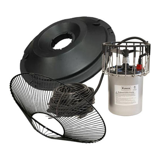
Back to Contents PARTS INCLUDED (2HP) 3 mooring ropes Item Description Part No. Float section (2HP) 284001 3/8"-16 X 9.5" hex head screw 840159 3/8" lock nut 462214 Top float bracket 840157 3/8" x 1" bolt 566250 3/8" lock washer 566230 Bottom float bracket 840158... -
Page 7: Parts Included (3-5Hp)
Back to Contents PARTS INCLUDED (3-5HP) 3 mooring ropes Item Description Part No. Float section (3HP, 5HP) 251001 3/8"-16 X 9.5" hex head screw 840159 3/8" lock nut 462214 Top float bracket 840157 3/8" x 1" bolt 566250 3/8" lock washer 566230 Bottom float bracket 840158... -
Page 8: Assembly Instructions (2Hp)
Back to Contents ASSEMBLY INSTRUCTIONS (2HP) 1. Arrange the three float sections (A) upright Plug (plug on bottom) so the overlap of one sec- tion aligns with the next section and loosely push the three sections together to form a continuous ring. - Page 9 Back to Contents ASSEMBLY INSTRUCTIONS (2HP, CONT.) 8. Lift the float assembly and place it over the aerator. Adjust one unit mounting bracket (H) at a time. Nest the cage ring in the middle notch of the unit mounting bracket. Attaching the unit mounting brackets is easiest with another person to assist in holding and repositioning the float as needed.
-
Page 10: Optional Bottom Screen Assembly
Back to Contents OPTIONAL BOTTOM SCREEN ASSEMBLY Optional Mesh Screen Attachment If you are not using a mesh screen, proceed to step 6. 1. Wrap the flat mesh (K) into a cone shape by overlapping both vertical edges by approximately 1 inch and aligning the top and bottom edges of mesh. -
Page 11: Assembly Instructions (3-5Hp)
Back to Contents ASSEMBLY INSTRUCTIONS (3-5HP) 1. Arrange the three float sections (A) upright so the overlap of one section aligns with the next section and loosely push the three sec- tions together to form a continuous ring. Float down Float up 2. - Page 12 Back to Contents ASSEMBLY INSTRUCTIONS (3-5HP, CONT.) Optional Bottom Screen Assembly If you purchased the optional bottom screen, see assembly instructions on page 9. Note that instructions feature drawings of the 2HP model, but the steps are the same for 2HP and 3HP-5HP models. Cord Strain Relief On power cords 100 feet or longer with the watertight Quick Disconnect, the power cord is shipped sepa- rately.
-
Page 13: Installation Instructions
Back to Contents INSTALLATION INSTRUCTIONS Use ropes to position the aerator in the desired location in the pond or lake. Anchor the ropes or secure them to the shoreline so that they are free of slack, but not tight. To prevent twisting of the unit due to motor torque, place the anchor at least 3 feet from the float for each foot of depth. -
Page 14: Three-Phase Startup Procedure
Keep clear of the propeller while verifying rotation. Air will be blowing out of (up, away from) the unit when rotating in the correct direction. If a Kasco 3-phase panel is supplied, follow the instructions included with the panel in addition to the steps below. -
Page 15: Maintenance Recommendations
If you have repeat/consistent trips on your ground fault, disconnect the equip- ment and remove it from the water. Inspect the power cord for damage and call Kasco Marine at 715- 262- 4488 for further instructions. -
Page 16: Troubleshooting Tips
A Ground Fault Interrupter (GFI) breaker that trips can indicate an electrical service problem, water contamination in the unit and/or cord, bad breaker, control box problems, motor problems, etc. Try to find out the answers to these questions before you contact Kasco to narrow down the problem. - Page 17 “My aerator turns itself off and back on without the timer and without tripping the GFI breaker.” (for single phase units only) Each Kasco unit has a thermal overload built in that will turn the unit off when it overheats. Once the unit has cooled down, it will start back up. If you are noticing these symptoms, the unit should be unplugged immediately because the thermal overload will continue to turn on and off until it burns out and damages the motor.
-
Page 18: Replacement Parts (2Hp)
Back to Contents REPLACEMENT PARTS (2HP) Description Part # Propeller (2HP) 820505 Sacrificial anode assembly (5/8” shaft) 840475 Cage 993200 3/8”-16 x 1-1/4” serrated flange screw 840543 3/8”-16 serrated flange nut 840532 Sealed motor unit 2HP-5HP AERATOR MANUAL... -
Page 19: Replacement Parts (3-5Hp)
Back to Contents REPLACEMENT PARTS (3-5HP) Description Part # Propeller (3HP) 821213 Propeller (5HP) 821210 1/2" washer 475642 Sacrificial anode assembly (5/8" shaft) 840475 Aerator mounting ring 993300 Retaining clip 140312 1/4" flat washer 258476 1/4" split lock washer 840537 1/4"-20 x 3/4"... -
Page 20: Warranty
Any expedited shipping method for the return under this warranty is limited to replacing or repair- of the unit is at the customer’s expense. Kasco Ma- ing free of charge any defective part within the war- rine will return units repaired under warranty at our ranty period. - Page 21 (for return delivery of the repaired unit), daytime phone number, and an e-mail address for correspondence regarding the warranty claim. Any expedited shipping method for the return of the unit is at the customer’s expense. Kasco Marine will return units repaired under warranty at our expense via ground freight within the continental United States.
-
Page 22: Repair Contact Form
Back to Contents REPAIR CONTACT FORM • Kasco requires that all equipment sent for repair MUST be accompanied by this form and marked to Repairs attention. Kasco Marine • Unit should be cleaned before shipping. 800 Deere Road • Kasco is NOT responsible for shipping damage accrued in Prescott, WI 54021 return shipment.
Need help?
Do you have a question about the 8400A and is the answer not in the manual?
Questions and answers