
Related Manuals for Stevens AeroModel Dystraction backyard /Indoor F3A


Summary of Contents for Stevens AeroModel Dystraction backyard /Indoor F3A
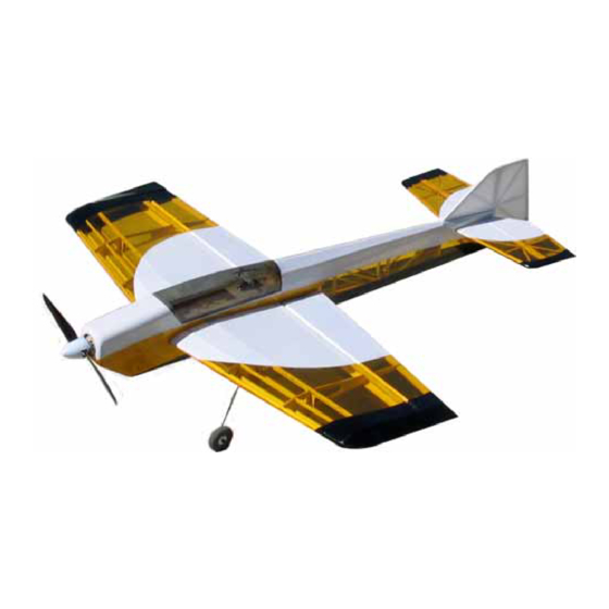
- Page 1 / Indoor F3A 1.01 Span 24.5” / Length 29.25” / Area 185 Sq.” / Weight 6-8oz © 2003 Stevens AeroModel. Page 1 of 20...
- Page 2 Poly Sheet Protector for Plans (Wax paper or Plastic Wrap will work in a pinch) Straight Edge Razor Blade(s) Coarse / Med / and Fine Grit Sand Paper Rat-Tail File Tape Clear and Masking Balsa Wood Filler Glass Cleaner Solution (Windex) © 2003 Stevens AeroModel. Page 2 of 20...
- Page 3 GENERAL ASSEMBLY INSTRUCTIONS: Thank you, for purchasing this Stevens Aeromodel Dystraction Backyard / Indoor F3A. This kit provides the builder and pilot a refreshing change of pace from heavy “ARF” style plywood box airframe construction and blends stick and tissue design methods of the past with state of the art CAD technology and precision interlocking laser cut parts;...
-
Page 4: Tail Feathers
Align parts with rolled plan sheet and wick CA into joints. Note that each fuselage side has a side marked “inside” also note the detail on the plan sheet for installing the elevator servo SR3a/3b block to one fuselage side. © 2003 Stevens AeroModel. Page 5 of 20... - Page 5 Only apply enough glue to tack the assembly together we still want the parts to have the ability to shift. Attach opposite fuselage side and tack into position with thin CA. © 2003 Stevens AeroModel. Page 6 of 20...
- Page 6 Install balsa former F1a. Next laminate F1b Ply firewall to surface of F1a. Complete by laminating F1c and F1d to face of F1b completing the front firewall. Review plan sheet illustrations for more detail. © 2003 Stevens AeroModel. Page 7 of 20...
- Page 7 Tack glue deck FT1 to fuselage tab and notch points. Review plan sheet illustrations for more detail. 10. Install 1/16” balsa servo pocket doublers SR1, SR2, SR3c to inside of fuselage as illustrated on the plan sheet. © 2003 Stevens AeroModel. Page 8 of 20...
- Page 8 12. Key FT2 into position spanning F8 / F9 and Fuselage Sides. 13. Key the F11 turtle deck spine into position as illustrated. F11 spans F6, F7, F8, and FT2. Tack glue F11 at each former joint. © 2003 Stevens AeroModel. Page 9 of 20...
- Page 9 NOTE: it is often helpful to spray the outside of the sheet with a glass cleaner solution or mixture of alcohol / water to facilitate bending along the radius of the formers. © 2003 Stevens AeroModel. Page 10 of 20...
- Page 10 45 degree bevel in one end of the tubing to allow it to facilitate snaking the tube through the holes in each former. The rudder gets two tubes that should exit on either side of the fuselage just aft of former F7. SEE DETAIL ON PLAN SHEET © 2003 Stevens AeroModel. Page 11 of 20...
- Page 11 Invert the wing assemblies and key each assembly halve into the upper spar cap strip sub-assembly S3. Note that the spar cap strip will attempt to set the angle of each rib. Friction fit all parts at this point in the assembly. © 2003 Stevens AeroModel. Page 12 of 20...
- Page 12 IN BETWEEN each rib. Do not apply glue to any rib/spar joint at this point. Gently work the leading edge jig, sub-assembly LE, into position. Key the 1/16” balsa trailing edge jig TE1 but do not glue. © 2003 Stevens AeroModel. Page 13 of 20...
- Page 13 Complete the leading edge by laminating the 3/32” balsa center section leading edge doubler strips, LE4, to the top and bottom of the center section leading edge jig. © 2003 Stevens AeroModel. Page 14 of 20...
- Page 14 11. Double either side of ribs R2 with the 1/32” ply parts R2A. This forms the gear pocket so do a good job of wicking thin CA into all joints adding a bit of CA to the inside of the pocket to harden this area. © 2003 Stevens AeroModel. Page 15 of 20...
- Page 15 – remove all high spots that prevent the wing from fitting within the fuselage. Slowly work the wing and do not force parts to fit. © 2003 Stevens AeroModel. Page 16 of 20...
- Page 16 Test Fit gear legs to wing pockets. DO NOT GLUE gear in-place until after you have covered and fit the wing to the fuselage. Canopy Trim canopy along scribe line on the molded part and test fit to fuselage. © 2003 Stevens AeroModel. Page 17 of 20...
-
Page 17: Final Assembly
CG point by shifting these components – then go back and place your Velcro in position to retain your components where they did the best job of balancing the model. © 2003 Stevens AeroModel. Page 18 of 20... -
Page 18: First Flight
/ cutting / hardware / parts. Please contact us e-mail is the preferred method though you are welcome to contact us by phone as well: Stevens AeroModel 4550 Beaumont Rd. Colorado Springs, CO 80916 Voice: 719-310-5691 sales@stevensaero.com www.stevensaero.com © 2003 Stevens AeroModel. Page 19 of 20... - Page 19 THIS PAGE HAS BEEN PROVIDED TO SCHEME A COLOR SCHEME: © 2003 Stevens AeroModel. Page 20 of 20...
Need help?
Do you have a question about the Dystraction backyard /Indoor F3A and is the answer not in the manual?
Questions and answers