
Related Manuals for Ingenico iUI120


Summary of Contents for Ingenico iUI120
- Page 1 Ingenico Unattended Product iUI120 Ingenico – 28-32 Boulevard de Grenelle - 75015 PARIS Tél. 33(0)1 58 01 80 00 - Fax 33 (0)1 58 01 91 35...
- Page 2 The scope of this document is to assist third party integrators when dealing with iUI120 Ingenico Unattended product. It offers all information needed for a successful integration of iUI120 product into unattended kiosk machines. For any sales information please refer to your Ingenico contact into the region.
-
Page 3: Table Of Contents
Table of contents GENERAL ......................6 Definition of acronyms ..................6 iUI120 payment solution presentation ............7 1.2.1 Diagram of iUI120 connectivity and communications ..........8 1.2.2 Services ......................... 9 Description of iUI120 product ................ 10 1.3.1 iUI120 product views .................... 10 1.3.2... - Page 4 Volume for iUI 120 without cable gasket ............... 45 6.1.2 Volume for iUI 120 with cable gasket ..............46 Kiosk preparation for iUI120 new installation ............47 Installing the iUI120 in new kiosk ..............48 6.1.1 Left horizontal on a shelve inside the kiosk ............48 6.1.2...
- Page 5 Environmental specification continued ............. 55 10.4 EC standard compliance marking .............. 56 10.5 IC statements ....................56 10.6 FCC Statement ..................... 57 10.7 Environment (WEEE, Batteries and Packaging) ........58 Intégration Guide_iUI120 5/58 Copyright © 2013 Ingenico 900016253 R11 000 01/1416 All rights reserved...
-
Page 6: General
Secure Access Module – the chips storing the electronic cash register in a stored value scheme such as Moneo, Proton or VISA Cash. SubMiniature version A Universal Serial Bus Intégration Guide_iUI120 6/58 Copyright © 2013 Ingenico 900016253 R11 000 01/1416 All rights reserved... -
Page 7: Iui120 Payment Solution Presentation
1.2 IUI120 PAYMENT SOLUTION PRESENTATION The iSelf Series is the new range of Ingenico unattended devices to offer payment into any kiosk through any segments (petrol, transport, vending, parking, etc.). The modules for iSelf Series are: for contactless reading, iUC150,iUC180,iUC180B for contact and magnetic strip reading, iUR250 for PinPad entry , IUP250. -
Page 8: Diagram Of Iui120 Connectivity And Communications
1.2.1 Diagram of iUI120 connectivity and communications iUI120 Ethernet 1USB device 4 USB host 10 – 45 V Max Power supply Serial port com0 display (Option) GSM / GPRS MDB slave (Option) Bluetooth Keypad Main Power MDB master (Option) supply... -
Page 9: Services
User licence for M²OS − Softwares / Licences Licence for software signature tool, SAT − Licence for "EMV Level 2 package " − Licence for TCP/IP − … Intégration Guide_iUI120 9/58 Copyright © 2013 Ingenico 900016253 R11 000 01/1416 All rights reserved... -
Page 10: Description Of Iui120 Product
1.3 DESCRIPTION OF IUI120 PRODUCT 1.3.1 iUI120 product views Front view Rear view Intégration Guide_iUI120 10/58 Copyright © 2013 Ingenico 900016253 R11 000 01/1416 All rights reserved... -
Page 11: Iui120 Technical Hardware Characteristics
Mass 247 g 134 x 106 x 48 mm (height x width x Dimensions depth) Power Supply iUI120 : 10 – 45 V Max Platform Telium2 Memory 16 Mb SDRAM and 128 Mb Flash Buzzer RGB led internal status indicator 1 Maintenance Button µSD... - Page 12 Range Bluetooth Class 2 – mini 10m in free sight Operating conditions Functional temperature* -20° C, +65° C Max relative humidity 85% at 55° C, non-condensing Intégration Guide_iUI120 12/58 Copyright © 2013 Ingenico 900016253 R11 000 01/1416 All rights reserved...
-
Page 13: Iui120 Output Connectors Description
1.3.3 iUI120 output connectors description Slave Master COM 0 Top view µSD 2 SAMs COM2 Link Wake-Up Link Right view Intégration Guide_iUI120 13/58 Copyright © 2013 Ingenico 900016253 R11 000 01/1416 All rights reserved... - Page 14 Hosts Device Ethernet Bottom view Bluetooth Antenna GPRS Antenna LLT/Maintenance LLT/Maintenance Button Left view Intégration Guide_iUI120 14/58 Copyright © 2013 Ingenico 900016253 R11 000 01/1416 All rights reserved...
-
Page 15: Ethernet
The iUI120 unit can be connected to serial port COM0. The connector type is RJ11. Pin N° Function Wake-up 1.3.3.5 COM2 link (optional) The iUI120 unit can be connected to serial port COM2 if the option is available. The connector type is RJ11. Pin N° Function Wake-up Intégration Guide_iUI120 15/58 Copyright ©... -
Page 16: Mdb Slave
The iUI120 unit is powered on the MDB connectors by power supply 10 to 45V DC (45V is a maximum). See below iUI120 unit can be connected by MDB master if option available. The connector type is MDB master 8 pins (Mini – Fit series 87827 (MOLEX)). -
Page 17: Wake-Up Jack
WARNING : The specific jack and cable is a spare part, contact commercial service to purchase it. Warning: do not plug-in a DC power in the jack. It could damage the iUI120. 1.3.3.9 Bluetooth (optional) When the iUI120 unit is ordered with Bluetooth option, it must be connected to an external Bluetooth antenna. -
Page 18: Gprs (Optional)
When iUI120 product is provided with GPRS functionality (configuration upon request), the external antenna is not provided with the unit. Ingenico can provide an antenna, or a standard one can be used. This standard Antenna must have an impedance of 50 Ohm and a maximum gain of 3.5 dBi. -
Page 19: Sam & Μsd Installation
1.3.3.11 SAM & µSD Installation 1. Disconnect the iUI120 unit from the main power supply. 2. Open the SAM door by removing the screw. 3. Insert the SAM cards in SAM slot 1 and /or slot 2 4. Insert µSD card in µSD slot 5. -
Page 20: Buzzer
The iUI120 have a black and white display. 1.3.3.14 Maintenance Button and LED The iUI120 unit has a maintenance button at the back. To enter LLT mode, press the button at power up or at restart, until the red LED lights on. -
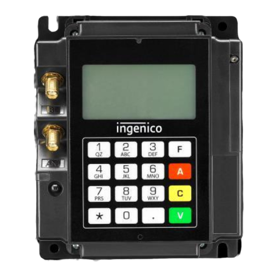
Page 21: Iui 120 Keypad
120 Keypad Remarks: The rear display and the keyboard can only be used in maintenance mode. “*” and “.” are used for Up and Down. Intégration Guide_iUI120 21/58 Copyright © 2013 Ingenico 900016253 R11 000 01/1416 All rights reserved... -
Page 22: Cable Protection
1.3.3.16 Cable Protection A cable sealing sleeve is provided with iUI120 unit to protect the top of product against water runoff. Connect the cables, and snap in the part on the rear cover to cover the cables. This sleeve also holds the antenna tool for GPRS and BT options. -
Page 23: Antenna Installation
2. Insert the SMA antenna cable through the slot of the antenna tool. 3. Slide the antenna tool over the SMA Cable connector. 4. Screw the cable. Antenna tool rest position Intégration Guide_iUI120 23/58 Copyright © 2013 Ingenico 900016253 R11 000 01/1416 All rights reserved... -
Page 24: Professional Installation Requirement
1.4 PROFESSIONAL INSTALLATION REQUIREMENT Ingenico only sells its products, to qualified partners and integrators. They are in charge of professionally resell, integrate, and install these products inside complete solution for end customers. These end customers solution can be: • Petrol station. -
Page 25: Wake-Up Function A Revoir
1.5 WAKE-UP FUNCTION A REVOIR 1.5.1 Wake-up mechanism iUI120 unit iUI120 unit is designed to save power thanks to a “stand-by mode”. If the stand-by mode is used, use Wake-up mechanism: with button connected on jack (optional) with Pin 2 of COM0 link & COM2 link by pressing the green key on the maintenance keyboard. -
Page 26: Recommended Circuit Implementation
1.5.2 Recommended circuit implementation Intégration Guide_iUI120 26/58 Copyright © 2013 Ingenico 900016253 R11 000 01/1416 All rights reserved... -
Page 27: Power-On Sequence Iui120/Iur250/Iuc150
1.5.3 Power-On sequence iUI120/iUR250/iUC150 This configuration describes the worst case for wake-up timing. Intégration Guide_iUI120 27/58 Copyright © 2013 Ingenico 900016253 R11 000 01/1416 All rights reserved... -
Page 28: Main Accessories
An optional USB cable (spare part reference 296129367) with short right-angle overmolded connectors can be purchased as an accessory. This cable is designed to optimize the required volume for iUI120 installation in the kiosk and allows the use of the cable sleeve. -
Page 29: Llt Cable
2.1.4 LLT cable Intégration Guide_iUI120 29/58 Copyright © 2013 Ingenico 900016253 R11 000 01/1416 All rights reserved... -
Page 30: Stand-By Management Cables
2.1.5 Stand-by management cables 2.1.5.1 Jack connector Definition of the jack connector: 2.1.5.2 COM0 and COM2 Specification available on demand. Intégration Guide_iUI120 30/58 Copyright © 2013 Ingenico 900016253 R11 000 01/1416 All rights reserved... -
Page 31: Iui120 Software
3 IUI120 SOFTWARE The system unit, equipped with Telium2 ® technology, is designed with a structure supporting several applications without any mutual interference. The operating system is a multi-task, real time, preemptive system. The inputs and outputs are managed by interrupts. -
Page 32: Software Architecture
Appli 2 Appli 3 Appli n The software architecture is divided into levels: • System • Multi-application manager • Universal Controller Module Component (UCMC) • Independent applications Intégration Guide_iUI120 32/58 Copyright © 2013 Ingenico 900016253 R11 000 01/1416 All rights reserved... -
Page 33: Secure Management Of Software
2. Before running a software, the terminal checks : • Its presence by looking for the software’s identity. • Its integrity by checking checksums and CRCs. Intégration Guide_iUI120 33/58 Copyright © 2013 Ingenico 900016253 R11 000 01/1416 All rights reserved... -
Page 34: Operating System
Inter-application isolation is managed by the Memory Management Unit (MMU). • Application download management: The operating system offers the downloading services described in the « Software download » section. Intégration Guide_iUI120 34/58 Copyright © 2013 Ingenico 900016253 R11 000 01/1416 All rights reserved... -
Page 35: Telium Manager
Date, time, message display language, IP network configuration data, local loading or remote diagnostics. System unit maintenance (in maintenance mode) The system unit has maintenance functions. • Properties • Local downloading • Diagnostics Intégration Guide_iUI120 35/58 Copyright © 2013 Ingenico 900016253 R11 000 01/1416 All rights reserved... - Page 36 • Using a special local loading tool connected to the terminal, • Using a remote loading tool, • Using a USB key. The iUI120 must be in maintenance mode with a USB key containing the software to load plugged in. Then, launch the download by...
-
Page 37: Software Downloading
• Remotely, via the switched telephone network (PSTN) using an external modem, Ethernet, GPRS, TCP/IP network. • By a USB key. The iUI120 must be in maintenance mode with a USB key containing the software to load plugged in. Then, launch the download by using the manager menu. - Page 38 The downloaded software is run in a secure context by authenticity check. Intégration Guide_iUI120 38/58 Copyright © 2013 Ingenico 900016253 R11 000 01/1416 All rights reserved...
- Page 39 Switch off the product Connect the PC to the COM or slave USB connector. Press the rear button and switch on the iUI120. When the LED near the button becomes fix red, release the button. “LLT” text is now displayed on screen.
-
Page 40: Development Station
The software is written in high level C language in a multi-application environment. Ingenico provides the complete set of software and the equipment required for development. This also includes the documentations. Training sessions can also be proposed. - Page 41 This includes the hot line, and updates to the documentations and softwares during this period. • Software package A set of software packages, used to simplify development of applications (EMV level 2, …) is available. Intégration Guide_iUI120 41/58 Copyright © 2013 Ingenico 900016253 R11 000 01/1416 All rights reserved...
-
Page 42: Terminal Management System
4 TERMINAL MANAGEMENT SYSTEM 4.1 INTRODUCTION Ingenico developed its own Terminal Estate Management System called IngEstate. It is a link between an organisation with an estate of payment terminals and their merchants. It allows users to remotely manage payment terminals, modify their software content and interact with merchants. -
Page 43: Installation Procedure In Kiosks
Note: It is required to use while handling these devices. ESD-protective clothing 5.1 SECURITY REQUIREMENT IUI120 Your device fulfils current applicable PCI PTS security requirements. Upon receipt of your terminal you should check for signs of tampering of the equipment. It is strongly advised that these checks are performed regularly after receipt. -
Page 44: General Installation Recommendations
• See environmental specification and especially in case of very cold or humid weather, take steps to ensure that the internal temperature is at least -20 ° C. Intégration Guide_iUI120 44/58 Copyright © 2013 Ingenico 900016253 R11 000 01/1416 All rights reserved... -
Page 45: Assembly Procedure For Iui120
6 ASSEMBLY PROCEDURE FOR IUI120 6.1 KIOSK MINIMUM VOLUME FOR IUI 120 The iUI120 requires a minimum volume inside the kiosk. It is detailed in the drawings below. 3D design is available on demand. 6.1.1 Volume for iUI 120 without cable gasket The minimum volume is 95.4 mm width x 115 mm height x 43 mm deep. -
Page 46: Volume For Iui 120 With Cable Gasket
6.1.2 Volume for iUI 120 with cable gasket The minimum volume is 101mm width x 135 mm height x 49 mm deep. Picture of iUI 120 with cable gasket minimum volume Intégration Guide_iUI120 46/58 Copyright © 2013 Ingenico 900016253 R11 000 01/1416 All rights reserved... -
Page 47: Kiosk Preparation For Iui120 New Installation
KIOSK PREPARATION FOR IUI120 NEW INSTALLATION IUI120 can support 3 different mounting ways: • Left horizontal on a shelve inside the kiosk • Mounted vertically on a support following EVA standard recommendation • Mounted vertically on a support using bolts or studs 3D step files are also available upon request. -
Page 48: Installing The Iui120 In New Kiosk
6.1.2 Mounted vertically on a support using EVA standard recommendation EVA recommends using 2 M4 cap bolts distant 68.4 mm to hold internal products. In addition, we suggest making a M4 holes to lock the iUI120 wit a screw. EVA mounting bolts M4 optional lock Intégration Guide_iUI120... - Page 49 Details of EVA mounting EVA M4 cap bolts. Can be weld or screwed on the kiosk. Dimensions on the iUI120 regarding position of the receptacles for EVA M4 bolts. Picture showing a new installation of the iUI120 Intégration Guide_iUI120 49/58 Copyright ©...
-
Page 50: Mounted Vertically On A Support Using Bolds Or Studs
6.1.3 Mounted vertically on a support using bolds or studs Common installation may consider to use 2 weld studs or bolds. We suggest using 2 diagonally opposite slots out of the 4of iUI120. 2 diagonally opposite weld studs, bolds or holes. - Page 51 Detail of dimensions on the iUI120 for 2 diagonally opposite slots mounting. Intégration Guide_iUI120 51/58 Copyright © 2013 Ingenico 900016253 R11 000 01/1416 All rights reserved...
-
Page 52: Maintenance
7.1 CONFIGURATION The iUI120 unit supplied to you has operational configuration loaded. In factory, software is loaded in the iUI120, as well as parameter definition files. The parameter definition file of the UCMC component is used, in particular, to determine the type of printer used (local/host) and the position of the host (COMx). -
Page 53: Disassembling The Products According To Weee Directive
Ce document est destiné aux installations de traitement et de recyclage. Il fournit les instructions de base pour le démontage de produits Ingenico afin de retirer les composants et matériaux nécessitant un traitement sélectif, tel que défini par la directive européenne 2002/96/CE, sur les Déchets d’Equipements Electriques et Electroniques (DEEE). -
Page 54: Product Disassembly Process
Oter les 4 vis maintenant l’entretoise plastique. Oter l’entretoise plastique, puis la tôle arrière, puis le support plastique de l’antenne Remove the keypad card and the displays. Oter la carte clavier et les afficheurs Intégration Guide_iUI120 54/58 Copyright © 2013 Ingenico 900016253 R11 000 01/1416 All rights reserved... -
Page 55: Standards
< 1,44W Value measured for Power supply 12V at 25° C • Max Power device in stand-by mode : o iUI120 < 4,8 mW Value measured for Power supply 12V at 25° C • Back up battery life o 1 storage year + 7 years in field at 45 days/year storage rate (25°... -
Page 56: Ec Standard Compliance Marking
: (1) l'appareil ne doit pas produire de brouillage, et (2) l'utilisateur de l'appareil doit accepter tout brouillage radioélectrique subi, même si le brouillage est susceptible d'en compromettre le fonctionnement. Intégration Guide_iUI120 56/58 Copyright © 2013 Ingenico 900016253 R11 000 01/1416 All rights reserved... -
Page 57: Fcc Statement
This device must be installed to provide a separation distance of at least 20cm from all persons and must not be co-located or operating in conjunction with any other antenna or transmitter. Intégration Guide_iUI120 57/58 Copyright © 2013 Ingenico 900016253 R11 000 01/1416 All rights reserved... -
Page 58: Environment (Weee, Batteries And Packaging)
The associated symbol means that WEEE and waste batteries must not be thrown away but collected separately and recycled. Ingenico ensures that efficient collection and recycling schemes are set-up for WEEE and batteries according to the local regulation of your country. Please contact your retailers for more detailed information about the compliance solution in place for disposing of your old product and used batteries.
Need help?
Do you have a question about the iUI120 and is the answer not in the manual?
Questions and answers