Table of Contents
Advertisement
Quick Links
Advertisement
Table of Contents

Related Manuals for MICRO-EPSILON FSC1/7


Summary of Contents for MICRO-EPSILON FSC1/7
- Page 1 Operating Instructions FSC1/7, FSC1000...
- Page 2 Layer thickness measuring device for insulators on metal and carbon fiber-reinforced plastics (CFRP) MICRO-EPSILON MESSTECHNIK GmbH & Co. KG Königbacher Strasse 15 94496 Ortenburg/Germany Phone +49 (0) 8542/168-0 Fax +49 (0) 8542/168-90 email info@micro-epsilon.com www.micro-epsilon.com...
-
Page 3: Table Of Contents
Notes regarding FCC Approval ................. 6 Intended Use ..................... 7 Proper Environment ................... 7 Overview ................... 8 Structure, Functional Principle ................8 FSC1/7 and FSC1000 Technical Data ............... 9 Delivery ................... 10 Unpacking, Included in Delivery..............10 Storage ......................10 Initial Operation ................11 Dimensional Drawings .................. - Page 4 Managing Measurement Data ............31 5.8.4 Saving/Exporting Measurement Data ..........31 Ending the Measuring Program, Switching off the Controller ......33 Liability for Material Defects ............33 Cleaning, Service, Repair .............. 34 Decommissioning, Disposal ............34 License agreement, software ............35 FSC1/7, FSC1000...
-
Page 5: Safety
Avoid exposure of sensor to aggressive media (detergents, cooling emulsions). > Damage to or destruction of the sensor Avoid bending, clamping and tensile stress of the sensor cable. > Damage or destruction of the sensor cable FSC1/7, FSC1000 Page 5... -
Page 6: Notes On Ce Marking
The measuring system is designed for use in industrial environments and meets the requirements. Notes regarding FCC Approval The FSC1/7 and FSC1000 are registered under the FCC identifier: 2AMBGMEMW02, equipment class - Part 15 Class B Computing Device Peripherals and - Part 15 Class C Low Power Communication Device Transmitter with the US Federal Communications Commission (FCC). -
Page 7: Intended Use
- Consult the dealer or an experienced radio/TV technician for help Intended Use - The FSC1/7 and FSC1000 are designed for use in industrial and laboratory applications. They are used to measure the thickness of paint and other electrically insulating layers on substrates such as carbon fiber-reinforced plastics (CFRP), CFRP with metallic lightning protection and metals. -
Page 8: Overview
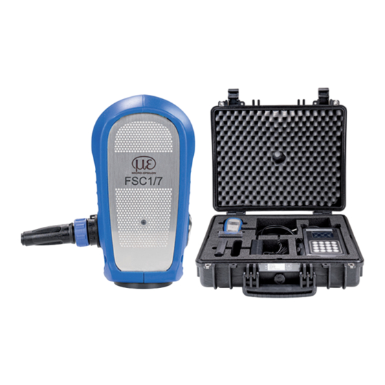
Overview Overview Structure, Functional Principle The FSC1/7 and the FSC1000 are suitable for thickness measurements of dielectric layers on - CFRP , - CFRP with lightning protection, - metals - and conductive or weakly conducting materials. The device includes a sensor (handheld module) and a controller (control and display module). The system operates based on microwaves. -
Page 9: Fsc1/7 And Fsc1000 Technical Data
Overview FSC1/7 and FSC1000 Technical Data Model FSC1/7 FSC1000 Measuring range 0 to 500 µm 0 to 1000 µm Linearity £ ±3 μm £ ±5 μm Repeatability £ 2 μm £ 4 μm Duration single measurement < 2 sec. ... -
Page 10: Delivery
Check the delivery for completeness and shipping damage immediately after unpacking. If there is damage or parts are missing, immediately contact the manufacturer or supplier. Storage Temperature range storage: 0 ... 45 °C (+32 ... +113 °F) FSC1/7, FSC1000 Page 10... -
Page 11: Initial Operation
Initial Operation Initial Operation Dimensional Drawings 54 (2.13) 68 (2.68) 48 (1.89) Fig. 3 Sensor dimensions, in mm (inches) Active measuring surface sensor FSC1/7, FSC1000 Page 11... - Page 12 Initial Operation 128 (5.04) 43 (1.96) Fig. 4 Controller dimensions, in mm (inches) FSC1/7, FSC1000 Page 12...
-
Page 13: Battery Pack
10%. The controller will switch off automatically when the status display reaches 0%. The status display for the battery becomes visible approximately one minute after the controller is switched Fig. 6 Battery state of charge FSC1/7, FSC1000 Page 13... -
Page 14: Fsc1/7 And Fsc1000 Operation
FSC1/7 and FSC1000 Operation FSC1/7 and FSC1000 Operation Switch-on Phase, Warm-up To prevent temperature and/or drift effects, which can lead to incorrect measurement results, proceed as follows: Switch on the controller. Sensor The ON LED in the upper right corner will light up. -
Page 15: Measuring Program Start
FSC1/7 and FSC1000 Operation Measuring Program Start After switching-on, the controller displays the start page, see Fig. Fig. 8 Controller start screen Fig. 9 No sensor connection The connection to the sensor is established when the sensor’s serial number is displayed at the bottom of the screen, see Fig. -
Page 16: Setup, Parameters
FSC1/7 and FSC1000 Operation Setup, Parameters In the Setup menu, see Fig. 10, settings can be configured via the pull-down menus. Measurement unit µm / mils An audible signal indicates successful/unsuccessful Buzzer output On / Off measurement. Time in the format hh:mm:ss... - Page 17 FSC1/7 and FSC1000 Operation Gray highlighted fields allow for a selection. Fig. 10 Setup menu FSC1/7, FSC1000 Page 17...
-
Page 18: Adjustment Of The Measuring System
FSC1/7 and FSC1000 Operation Adjustment of the Measuring System 5.5.1 General The Cal (calibration) menu makes it possible to load, manage and create adjustments. Fig. 11 Cal (calibration) menu Load Calibration Select and start existing adjustment table. Manage Manage, delete existing adjustment tables. -
Page 19: Load Adjustment Table
FSC1/7 and FSC1000 Operation 5.5.2 Load Adjustment Table Switch to the Load Calibration menu. Fig. 12 Data set selection Fig. 13 Data set details Select the desired file and confirm with the Load button. Once an adjustment is loaded, a window will appear with the basic information regarding the adjustment, see Fig. -
Page 20: Managing Adjustment Tables
FSC1/7 and FSC1000 Operation 5.5.3 Managing Adjustment Tables You can manage existing data sets in the Manage Calibration submenu. Possible options: - Del Deletes the selected data set - Load Loads the selected data set - ESC Back to measuring mode Fig. -
Page 21: Performing An Adjustment
FSC1/7 and FSC1000 Operation 5.5.4 Performing an Adjustment Only use undamaged calibration foils. Contamination, bends or damage within the black circle will lead to incorrect results. Only use the foil within the black circle for the adjustment. Foils are also available with a certificate. - Page 22 FSC1/7 and FSC1000 Operation Depending on the setup configuration, press the button on the sen- sor or keys 1 to 3 on the controller. The measurement will start appr. 300 ms after you release the button. Then enter the thickness of the calibration foil in the Thickness field in micrometers as an integer.
- Page 23 FSC1/7 and FSC1000 Operation Carry out this sequence with as many calibration foils as necessary and use the same position on the sub- strate to the extent possible. Stack the calibration foils if necessary. If information was entered for the parameters Measure count, Measure delay and Max delta in the setup, these settings will also be used for the adjustment.
- Page 24 FSC1/7 and FSC1000 Operation Press the OK button to save and end the adjustment. Use the Remove button to remove a support point during an adjustment. Fig. 19 List of support points during an adjustment You can change a selected support point using the Edit button.
- Page 25 FSC1/7 and FSC1000 Operation Then compare the result with the thickness value entered of the adjustment foil used. If the comparison result reveals an impermissible deviation, delete the support point and recreate it, see Fig. Fig. 21 Test result Use the Save Calibration Data field to assign a name to the adjustment data set.
-
Page 26: Performing A Measurement
FSC1/7 and FSC1000 Operation Performing a Measurement Load the adjustment data set suitable for the measurement/measurement object, see Chap. 5.5.2. The system will start the measuring mode. To measure the thickness, place the sensor on the component, avoid vibrations/tilting and trigger the measurement. - Page 27 FSC1/7 and FSC1000 Operation Measuring range -30 µm Adjustment range +30 µm 100 % Fig. 25 Measuring range limits If the measured thickness values are outside the ad- justed measuring range, the system will generate the message Out of range.
-
Page 28: Statistics
FSC1/7 and FSC1000 Operation Fig. 28 Creating a comment (left), excerpt from the measurement data file (right) Statistics In order to analyze the measurement data, the mean value and the standard deviation are determined for the measured values within the values listed. -
Page 29: Measurement Data
FSC1/7 and FSC1000 Operation Also in the statistics menu, each measured value is saved in the log file. When the menu is exited using the ESC button, a data set with the statistical information is stored in the log file, see Fig. -
Page 30: Displaying Measurement Data
FSC1/7 and FSC1000 Operation 5.8.2 Displaying Measurement Data The View Data menu shows the log of the current measure- ment series directly after opening. The pull-down menu in the upper part of the display enables the selection of a measurement series and shows this in the detail window. -
Page 31: Managing Measurement Data
FSC1/7 and FSC1000 Operation 5.8.3 Managing Measurement Data Sync Copies the previously selected log/measurement data file to a USB memory Deletes the selected file Load Opens the selected file with the data viewer, see Chap. 5.8.2. Returns to the start screen Fig. - Page 32 FSC1/7 and FSC1000 Operation After the data has been successfully saved, this is displayed. Fig. 34 Saving the measurement data If no data carrier is connected or it is not recognized, you will see a message. Fig. 35 Note: No USB storage medium found...
-
Page 33: Ending The Measuring Program, Switching Off The Controller
The liability for material defects is 12 months from delivery. Within this period, defective parts, except for wearing parts, will be repaired or replaced free of charge, if the device is returned to MICRO-EPSILON with shipping costs prepaid. Any damage that is caused by improper handling, the use of force or by repairs or modifications by third parties is not covered by the liability for material defects. -
Page 34: Cleaning, Service, Repair
Incorrect disposal may cause harm to the environment. Dispose of the device, its components and accessories, as well as the packaging materials in compliance with the applicable country-specific waste treatment and disposal regulations of the region of use. FSC1/7, FSC1000 Page 34... -
Page 35: License Agreement, Software
License agreement, software License agreement, software The software contained in this product includes a number of software components to which Micro-Epsilon or third-parties hold copyrights. This includes general components such as the operating system on the microcomputer used as well as specific components that were specially developed for the operation of the product. - Page 36 MICRO-EPSILON MESSTECHNIK GmbH & Co. KG X9751382-A051109SWE Königbacher Str. 15 · 94496 Ortenburg/Germany MICRO-EPSILON MESSTECHNIK Tel. +49 (0) 8542/168-0 · Fax +49 (0) 8542/168-90 *X975382-A05* info@micro-epsilon.com · www.micro-epsilon.com...
Need help?
Do you have a question about the FSC1/7 and is the answer not in the manual?
Questions and answers