Table of Contents
Advertisement
Quick Links
Ethernet Switch – Premium Line
IE-SW-PL10M Series (Managed)
Hardware Installation Guide
Fourth Edition, August 2016
1243400000/03/08.16
Please note:
This document, the detailed manual and any further
product information - if available - can be
downloaded at the internet link:
http://www.weidmueller.com/downloads
Copyright Notice
Copyright 2016 Weidmüller Interface GmbH & Co. KG
All rights reserved.
Reproduction without permission is prohibited.
Advertisement
Table of Contents

Related Manuals for Weidmüller Premium Line IE-SW-PL10M Series


Summary of Contents for Weidmüller Premium Line IE-SW-PL10M Series
- Page 1 Ethernet Switch – Premium Line IE-SW-PL10M Series (Managed) Hardware Installation Guide Fourth Edition, August 2016 1243400000/03/08.16 Please note: This document, the detailed manual and any further product information - if available - can be downloaded at the internet link: http://www.weidmueller.com/downloads Copyright Notice Copyright ...
-
Page 2: Package Checklist
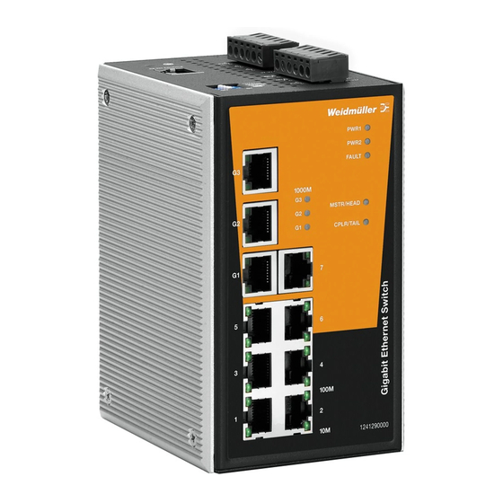
Package Checklist Your Ethernet switch is shipped with the following items. If any of these items are missing or damaged, please contact your Weidmüller customer service for assistance. 1 Ethernet Switch IE-SW-PL10M Hardware Installation Guide CD-ROM with User’s Manual and Windows Utility (option) ... - Page 3 Panel Views of IE-SW-PL10M Series 1 to 7: 10/100BaseT(X) port IE-SW-PL10M-3GT-7TX Front Panel View IE-SW-PL10M-3GT-7TX 10/100/1000BaseT(X) port IE-SW-PL10M-1GT-2GS-7TX 10/100/1000BaseT(X) port IE-SW-PL10M-3GT-7TX 10/100/1000BaseT(X) port IE-SW-PL10M-1GT-2GS-7TX 1000BaseSX/LX/LHX/ZX port IE-SW-PL10M-3GT-7TX 10/100/1000BaseT(X) port IE-SW-PL10M-1GT-2GS-7TX 1000BaseSX/LX/LHX/ZX port G1, G2, G3: LED indicators for IE-SW-PL10M-1GT-2GS-7TX 1000 Mbps ports Front Panel View PWR1: LED for power input 1 PWR2: LED for power input 2...
-
Page 4: Mounting Dimensions (Unit = Mm)
Top Panel: Ground screw RS-232 console port Heat dissipation orifices DIP switches for Ring Master, Ring Coupler, and Turbo Ring 6-pin terminal block for DI 1, DI 2, and PWR 2 6-pin terminal block for PWR1, Relay 1, and Relay 2 Rear Panel: Screw holes for Wall Mounting Kit DIN-Rail Kit... -
Page 5: Din-Rail Mounting
DIN-Rail Mounting The aluminum DIN-Rail attachment plate should already be fixed to the back panel of the IE-SW-PL10M when you take it out of the box. If you need to reattach the DIN-Rail attachment plate to the IE-SW-PL10M, make sure the stiff metal spring is situated towards the top, as shown by the following figures. - Page 6 ATTENTION This unit is a built-in type. When the unit is installed in another piece of equipment, the equipment enclosing the unit must comply with fire enclosure regulation IEC 60950/EN60950 (or similar regulation). ATTENTION Safety First! Be sure to disconnect the power cord before installing and/or wiring your Ethernet Switch.
-
Page 7: Wiring The Relay Contact
Wiring the Relay Contact The IE-SW-PL10M has two sets of relay outputs—relay 1 and relay 2. Each relay contact uses two contacts of the terminal block on the IE-SW-PL10M´s top panel. Refer to the next section for detailed instructions on how to connect the wires to the terminal block connector, and how to attach the terminal block connector to the terminal block receptor. -
Page 8: Wiring The Digital Inputs
Wiring the Digital Inputs The IE-SW-PL10M has two sets of digital inputs, DI 1 and DI 2. Each DI consists of two contacts of the 6-pin terminal block connector on the IE-SW-PL10M´s top panel, which are used for the two DC inputs. The top and front views of one of the terminal block connectors are shown here. -
Page 9: 10/100Baset(X) Ethernet Port Connection
RS-232 Connection The IE-SW-PL10M Series has one RS-232 (10-pin RJ45) console port, located on the top panel. Use either an RJ45-to-DB9 (see the cable following wiring diagrams) to connect the IE-SW-PL10M console port to your PC’s COM port. You may then use a console terminal program, such as Windows Hyper Terminal, to access the IE-SW-PL10M console configuration utility. -
Page 10: 1000Baset Ethernet Port Connection
RJ45 (8-pin, MDI-X) Port Pinouts Signal RJ45 (8-pin) to RJ45 (8-pin) Straight-through Cable Wiring RJ45 (8-pin) to RJ45 (8-pin) Cross-over Cable Wiring 1000BaseT Ethernet Port Connection 1000BaseT data is transmitted on differential TRD+/- signal pairs over copper wires. MDI/MDI-X Port Pinouts Signal TRD(0)+ TRD(0)-... -
Page 11: Turbo Ring Dip Switch Settings
1000BaseSFP (mini-GBIC) Fiber Port The gigabit Ethernet ports on the IE-SW-PL10M-1GT-2GS-7TX are 1000BaseSFP Fiber ports, which require using the gigabit mini-GBIC fiber transceivers to work properly. Weidmüller provides completed transceiver models for different distance requirement. Please refer to Specifications section for more optical fiber information. The concept behind the LC port and cable is quite straightforward. - Page 12 IE-SW-PL10M-Series DIP Switches The default setting for each DIP Switch is OFF. The following table explains the effect of setting the DIP Switch to the ON position. “Turbo Ring” DIP Switch Settings DIP 1 DIP 2 DIP 3 DIP 4 ON: Enables this ON: Enables the ON: Activates...
-
Page 13: Led Indicators
LED Indicators The front panel of the Weidmüller IE-SW-PL10M Series contains several LED indicators. The function of each LED is described in the following table: Color State Description Power is being supplied to power input P1. PWR1 AMBER Power is not being supplied to power input P1. Power is being supplied to power input P2. -
Page 14: Specifications
Specifications Technology Standards IEEE802.3, 802.3u, 802.3x, 802.1D, 802.1w, 802.1Q, 802.1p, 802.1X, 802.3ad, 802.3z Protocols IGMPv1/v2, GMRP, GVRP, SNMPv1/v2c/v3, DHCP Server/Client, BootP, TFTP, SNTP, SMTP, RARP, RMON, HTTP, HTTPS, Telnet, Syslog, DHCP Option 66/67/82, SSH, SNMP Inform, Modbus/TCP, LLDP, IEEE 1588 PTP, IPv6 MIB-II, Ethernet-like MIB, P-BRIDGE MIB, Q-BRIDGE MIB, Bridge MIB, RSTP MIB, RMON MIB Group 1,2,3,9... - Page 15 Power Input Voltage 24 VDC (12 to 45 VDC), redundant inputs Input Current (@24V) IE-SW-PL10M-3GT-7TX: 0.65A IE-SW-PL10M-1GT-2GS-7TX: 0.44A Connection Two removable 6-pin terminal blocks Overload Current Protection Present Reverse Polarity Protection Present Mechanical Casing IP30 protection, metal case Dimensions (W H D) 80.5 ...
- Page 16 Weidmüller gives a 5 year warranty on this product in accordance with the warranty terms as described in the general conditions of sale of the Weidmüller company which has sold the products to you. Weidmüller warrants to you that such products the defects of which have already existed at the time when the risk passed will be repaired by Weidmüller free of charge or that Weidmüller will provide a new, functionally equivalent product to replace the defective one.
Need help?
Do you have a question about the Premium Line IE-SW-PL10M Series and is the answer not in the manual?
Questions and answers