
Related Manuals for Weidmüller IE-SW-AL05M-5TX


Summary of Contents for Weidmüller IE-SW-AL05M-5TX
- Page 1 Industrial Ethernet managed Switches Manual Lite Advanced Line Switches IE-SW-AL05M-5TX (2682250000) IE-SW-AL06M-4TX-2SC (2682260000) IE-SW-AL06M-4TX-2SCS (2682270000) Third Edition, May 2023...
- Page 2 Industrial Ethernet managed Switches Manual The software described in this manual is furnished under a license agreement and may be used only in accordance with the terms of that agreement. Copyright Notice Copyright ©2016 Weidmüller Interface GmbH & Co. KG All rights reserved.
-
Page 3: Table Of Contents
User Manual Managed Switches Table of Contents 1. About this Manual ..................... 3 2. Getting Started ....................3 2.1 Hardware features ........................3 2.2 Software features ........................3 3. Web Management ....................4 3.1 Accessing the Web interface via HTTP ................4 3.2 Accessing the Web interface via HTTPS ................ - Page 4 User Manual Managed Switches 3.5.6.4 Information RSTP ....................33 3.5.6.5 RSTP-Repeater ..................... 34 3.5.7 Fast Recovery ........................ 34 3.6 Virtual LAN ..........................35 3.6.1 The Virtual LAN (VLAN) Concept .................. 35 3.6.2 Configuring port-based Virtual LAN ................36 3.7 DHCP Server/Relay ......................37 3.7.1 Configuring DHCP Server ....................
-
Page 5: About This Manual
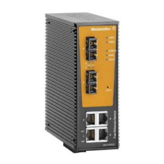
The products come with an IP30 rugged case, redundant power input, alarm relay and wide operating temperature range from -40 to 75ºC. 2.1 Hardware features • IE-SW-AL05M-5TX: 5 x 10/100Base-T(X) ports • IE-SW-AL06M-4TX-2SC 4 x 10/100Base-T(X) ports 2 x 100Base-FX ports (SC connector), multimode •... -
Page 6: Web Management
User Manual Managed Switches O-Ring (optimized protocol for ring topologies; recovery time < 10ms) O-Chain (allows multiple redundant network topologies; recovery time < 10ms) Fast Recovery • IP-address management Static DHCP-Client DHCP-Server (port based, pool based) DHCP Option 82 DHCP-Relay •... - Page 7 User Manual Managed Switches NOTE: Before accessing the Switch’s web browser interface, first connect one of its RJ45 Ethernet ports to your Ethernet LAN, or directly to your PC's Ethernet card (NIC). You can establish a connection with either a straight-through or cross-over Ethernet cable.
-
Page 8: Accessing The Web Interface Via Https
User Manual Managed Switches NOTE: The pages of the Web interface include a Help button that describes the parameters and functions that can be programmed or monitored in each web page. NOTE: After changing any parameter / function in a web page the button Apply activates the change but does not save it. -
Page 9: System Setting
User Manual Managed Switches 3.3.1 System Setting The system identification items are displayed at the top of the web page. You can configure the System Identification items to make it easier to identify different switches that are connected to your network. - Page 10 User Manual Managed Switches NOTE: The Switch's default user name / password are “admin” / ”Detmold”. If these are changed, then you will be required to type the new user name and password when logging into the serial console, Telnet console, or Web console. The button Show Passwords/Hide Passwords can be used to see as readable text or not the introduced password characters.
-
Page 11: Ip Setting
User Manual Managed Switches 3.3.3 IP Setting The IPv4 settings allow the user to set manually the IP parameters or by means of a DHCP server. See a brief explanation of each configuration item below. IP assignment Factory Setting Description Default The Weidmüller switch’s IP address must be set Static... -
Page 12: Ipv6 Setting
User Manual Managed Switches DNS1 and DNS2 Factory Setting Description Default 1st DNS Server’s The IP address of the DNS Server used by your None IP address network. The IP address of the secondary DNS Server used by 2nd DNS Server’s your network. -
Page 13: Time Setting
User Manual Managed Switches form of the interface identifier (Switch’s MAC address) 3.3.5 Time Setting The Time Setting configuration page lets users set the time, date, and other settings. An explanation of each setting is given below the figure. NOTE: The Weidmüller switch does not have a real time clock. The user must update the Current Time and Current Date to set the initial time for the Weidmüller switch after each reboot, especially when the network does not have an Internet connection for an NTP server or there is no NTP server on the LAN. - Page 14 User Manual Managed Switches Allows configuration of the local time in 24-hour System Time None format. SNTP/NTP mode Setting Description Factory Default Disabled No NTP/SNTP used in the switch. Server (NTP) The Weidmüller switch can synchronize other switches of the network with its programmed time Disabled clock.
-
Page 15: Lldp Function
User Manual Managed Switches 3.3.6 LLDP Function 3.3.6.1 Overview Defined by IEEE 802.11AB, LLDP is an OSI Layer 2 Protocol that standardizes the methodology of self-identity advertisement. It allows each networking device, e.g. a Weidmüller managed switch, to periodically inform its neighbors about its self-information and configurations. As a result, all of the devices would have knowledge about each other;... -
Page 16: Modbus Tcp
In the Appendix B, Modbus Register Table, the user can find all the available registers of the switch. 3.3.8 DIP Switch This option is available only in the IE-SW-AL05M-5TX model. It allows the user to enable or disable the settings of the 4 DIP switches located on the front of the switch housing. -
Page 17: Backup & Restore
User Manual Managed Switches If Mode is Enabled (and Apply is pressed), DIP switch SW1 defines the behavior of fault relay in terms of power failure and DIP switches SW2, SW3 and SW4 define the settings for O-Ring redundancy. If Mode is Disabled, the settings of the front DIP switches SW1/2/3/4 have no function. The behavior of the fault relay and the settings of O-Ring redundancy mode have to be configured through the web interface (Menu Warnings and Redundancy, respectively). -
Page 18: Upgrade Firmware
User Manual Managed Switches TFTP Server IP Address Factory Setting Description Default Specifies the IP address or name of the remote IP Address of TFTP server. Must be set up before None TFTP Server downloading or uploading files. Restore & Backup File Names Factory Setting Description... -
Page 19: Port Settings
User Manual Managed Switches Upgrade firmware from TFTP server TFTP Server IP Factory Setting Description Default Specifies the IP address of the remote TFTP IP Address of server. Must be set up before downloading the None TFTP Server firmware. Firmware File Name Factory Setting Description... -
Page 20: Port Status
User Manual Managed Switches NOTE: If a connected device or sub-network is wreaking havoc on the rest of the network, the Disabled option gives the administrator a quick way to shut off access through this port immediately. Speed/Duplex Setting Description Factory Default Allows the port to use the IEEE 802.3u protocol... -
Page 21: Loop Guard
User Manual Managed Switches Port alias Setting Description Factory Default Max. 128 Name of the port. Example: PLC 1 None characters 3.4.4 Loop Guard Avoid maintenance/installation crews from mistakenly placing one cable on the same switch generating a loop problem. If Loop Guard is Active in one port, a loop in that port will be blocked if the loop happens on the switch itself. -
Page 22: The O-Ring Concept
User Manual Managed Switches • Fast Recovery When configuring a redundant ring, all switches on the same ring must be configured to use the same redundancy protocol. You cannot mix the O-Ring and STP/RSTP protocols on the same ring. The following table lists the key differences between the features of each protocol. Use this information to evaluate the benefits of each, and then determine which features are most suitable for your network. -
Page 23: Ring Coupling Configuration
User Manual Managed Switches For copper-based Gigabit Ethernet connections the link loss detection is not used as trigger for ring topology change due to the physical design, as a link loss recognition takes a time of several hundred millisecond. Instead, for copper-based Gigabit Ethernet connections control packets are sent cyclic to achieve the fast recovery time of 30ms (Method 2). -
Page 24: Dual Homing Configuration
User Manual Managed Switches methods (Physical link change detection and/or Cyclic sending of control packets every 10ms) the coupling backup line will be activated (including a topology change) after around 30 ms. NOTE: Only for two switches of an O-Ring network one coupling port may be enabled. 3.5.2.3 Dual Homing Configuration Dual Homing provides a redundant connection between an O-Ring network and an RSTP network. - Page 25 User Manual Managed Switches 1. Select Enabled in field Ring Redundancy. 2. If only a redundancy with 1 ring shall be created then do following: • Activate checkbox ‘Set as Ring Master’ if the switch shall be assigned as ring master For O-Ring configuration one switch needs to be configured as Ring Master.
-
Page 26: The O-Chain Concept
User Manual Managed Switches Max Age Count Setting Description Factory Default 0 to 1000 Number of lost control packets for initiating a ring topology change. Enable Ring Coupling Setting Description Factory Default Check Enables the Ring Coupling operation in the Switch. Does not enable the Ring Coupling operation in the Not checked Uncheck... - Page 27 User Manual Managed Switches For both above illustrated scenarios the overall network healing time can be calculated roughly to around 40 ms based on a proprietary method to force a MAC address table update for all connected Weidmüller switches. Recovery time for O-Chain connected to an RSTP network For a connection to an RSTP network the overall time for topology update after the chain is broken can be estimated as the calculated healing time of the used RSTP redundancy settings plus around 30 milliseconds for chain topology update.
-
Page 28: Configuring O-Chain
User Manual Managed Switches • BPDU control packets which will be sent cyclic from RSTP network to the O-Chain Edge ports will be blocked by both Edge ports as long as the chain is healthy. As result the RSTP network does not recognize any loop and sets for both RSTP ports the forwarding state •... -
Page 29: Stp / Rstp
User Manual Managed Switches Explanation of ‘Setting’ and ‘Status’ items Chain Redundancy Setting Description Factory Default Enabled Enable the O-Chain operation. Disabled Disabled Disable the O-Chain operation. Status Description Factory Default O-Chain redundancy disabled. Healthy The Chain is operating normally. Broken Any of the two links of the Chain is not connected. - Page 30 User Manual Managed Switches Spanning Tree Protocol (STP) was designed to help reduce link failures on a network, and provide an automatic means of avoiding loops. This is particularly important for networks that have a complicated architecture, since unintended loops in the network can cause broadcast storms. Weidmüller switches’...
-
Page 31: How Stp Works
User Manual Managed Switches If STP is enabled, it will detect duplicate paths and prevent, or block, one of the paths from forwarding traffic. In the following example, STP determined that traffic from LAN segment 2 to LAN segment 1 should flow through bridges C and A since this path has a greater bandwidth and is therefore more efficient. - Page 32 User Manual Managed Switches • All bridges must be able to communicate with each other. The communication is carried out using Bridge Protocol Data Units (BPDUs), which are transmitted in packets with a known multicast address. • Each bridge must have a Bridge Identifier that specifies which bridge acts as the central reference point, or Root Bridge, for the STP system—bridges with a lower Bridge Identifier are more likely to be designated as the Root Bridge.
- Page 33 User Manual Managed Switches has ceased to function. This will trigger the bridge to reconfigure the network to account for the change. If you have configured an SNMP trap destination, when the topology of your network changes, the first bridge to detect the change will send out an SNMP trap. Differences between STP and RSTP RSTP is similar to STP, but includes additional information in the BPDUs that allow each bridge to confirm that it has taken action to prevent loops from forming when it decides to enable a link to a...
-
Page 34: Configuring Rstp
User Manual Managed Switches • Bridge C is the Designated Bridge for LAN segment 3, because it has the lowest Root Path Cost for LAN Segment 3: • The route through bridges C and B costs 200 (C to B=100, B to A=100) •... -
Page 35: Information Rstp
User Manual Managed Switches The root of the Spanning Tree topology periodically sends out a “hello” message to other devices on the Numerical value network to check if the topology is healthy. The “hello input by user time” is the amount of time the root waits between sending hello messages. -
Page 36: Rstp-Repeater
User Manual Managed Switches 3.5.6.5 RSTP-Repeater RSTP-repeater is a simple function to pass a BPDU packet directly from one RSTP device to another as if they were directly connected. Mode Setting Description Factory Default Enabled Enable the RSTP-repeater operation. Disabled Disabled Disable the RSTP-repeater operation. -
Page 37: Virtual Lan
User Manual Managed Switches Mode Setting Description Factory Default Enabled/Disabled Select to enable the Fast Recovery function. Disabled Recovery Priority Setting Description Factory Default Select the priority (number from 1 to total number of Not included, 1 to ports) of each port. The connected port with the highest Not included total number of ports priority (lowest number) will be the active one and the... -
Page 38: Configuring Port-Based Virtual Lan
User Manual Managed Switches Switch A Backbone connects multiple switches Switch B Department Department 1 Department VLAN 1 VLAN 3 VLAN 2 Benefits of VLANs The main benefit of VLANs is that they provide a network segmentation system that is far more flexible than traditional networks. -
Page 39: Dhcp Server/Relay
User Manual Managed Switches Port Setting Description Factory Default Enable/Disable Set port to specific VLAN Group by Enable activating checkbox. (all ports belong to VLAN1) 3.7 DHCP Server/Relay To reduce the effort required to set up IP addresses, the Weidmüller switch comes equipped with DHCP server. -
Page 40: Configuring Dhcp Server
User Manual Managed Switches 3.7.1 Configuring DHCP Server STEP 1 → Set up the connected devices Set up those Ethernet-enabled devices connected to the Weidmüller switch for which you would like IP addresses to be assigned automatically. The devices must be configured to obtain their IP address automatically. -
Page 41: Dhcp Relay Agent (Option 82)
User Manual Managed Switches Factory Setting Description Default DNS Server’s IP The IP address of the DNS Server dynamically 0.0.0.0 address assigned to DHCP clients. Lease time Setting Description Factory Default Lease time of the Amount of time a network client will be allowed to use 168 hours pool (hours) a dynamic IP address in the network. - Page 42 User Manual Managed Switches DHCP Server IP Address 1st Server Setting Description Factory Default IP address / VID Assigns the IP address and VID of the 1st DHCP 0.0.0.0 / 1 for the 1st server that the switch tries to access. DHCP server 2nd Server Setting...
-
Page 43: Client List
User Manual Managed Switches DHCP Option 82 Remote ID Type Setting Description Factory Default Uses the switch’s IP address as the remote ID sub. Uses the switch’s MAC address as the remote ID sub. Uses a combination of the switch’s MAC address and Client-ID IP address as the remote ID sub. -
Page 44: Snmp
User Manual Managed Switches NOTE: Port and IP binding will only be active if DHCP Server mode is enabled in the switch. 3.8 SNMP Weidmüller managed Switches support SNMP V1, V2c, and V3. SNMP V1 and SNMP V2c use a community string match for authentication, which means that SNMP servers access all objects with read-only or read/write permissions using the community strings public and private by default. -
Page 45: Snmp Read/Write Settings
User Manual Managed Switches 3.8.1 SNMP Read/Write Settings SNMP Agent Versions Factory Setting Description Default Specifies the SNMP protocol version used to manage V1/V2c, or V3 V1/V2c the switch. SNMP V1, V2c Community Factory Setting Description Default Specifies the community string to authenticate the Max. - Page 46 User Manual Managed Switches Context Name Factory Setting Description Default Max. 32 Specifies the name string to authenticate the SNMP None characters V3 agent. User profile – User ID Factory Setting Description Default Max. 32 A string identifying a user name. None characters User profile –...
- Page 47 User Manual Managed Switches User profile – Privacy Factory Setting Description Default Max. 32 A string identifying the privacy pass phrase of the None characters created user. No-Priv Allows the user to access objects without encryption. Encryption will be based on DES protocol. No-Priv AES128 Encryption will be based on AES128 protocol.
- Page 48 User Manual Managed Switches Access Table – Context Prefix Factory Setting Description Default The context name as defined in the context table. Max. 32 The context name can be treated differently None characters depending on the setting of the Content Match Rule. Access Table –...
-
Page 49: Trap Settings
User Manual Managed Switches MIBView Table – View Name Factory Setting Description Default Max. 32 A string identifying the View name that will be used in None characters the Access Table. MIBView Table – SubOid-Tree Factory Setting Description Default The object identifier (OID) value for the created view Number (OID) None table. -
Page 50: Security
User Manual Managed Switches Server IP Setting Description Factory Default IP address Specifies the IP address of the trap server used by None your network. Community or V3 Security Name Setting Description Factory Default Character string Specifies the community string to use for None authentication (maximum of 32 characters). - Page 51 User Manual Managed Switches Management Security Mode Setting Description Factory Default Enabled or Enable or disable the control access to the Disabled Disabled management of the switch. When disabled, the access to the switch is allowed via HTTP, HTTPS, TELNET and SSH. When enabled, it is possible to restrict this access.
-
Page 52: Tacacs
User Manual Managed Switches Enable SSH Management Setting Description Factory Default Check Access through SSH is allowed Check Uncheck Access through SSH is not allowed Secure IP List Setting Description Factory Default IP address (up Defines an IP address that is allowed to access to the 0.0.0.0 to 10) management of the switch. -
Page 53: Warnings
User Manual Managed Switches Client Configuration Setting Description Factory Default Local / TACACS+ Indicate if the authentication verification to access Local through Telnet / Web is made using the local database of the switch or a remote TACACS+ server. 3.10 Warnings Since industrial Ethernet devices are often located at the endpoints of a system, these devices will not always know what is happening elsewhere on the network. -
Page 54: Configuring Email Warning
User Manual Managed Switches Warning Relay output is triggered when… Power Failure PWR 1 No power input in the first power supply module of the switch. PWR 2 No power input in the second power supply module of the switch. Warning e-mail is sent when…... -
Page 55: Email Settings
User Manual Managed Switches Log is registered when / Warning e-mail is sent when… System Events System restart Weidmüller switch is rebooted. Power Status Weidmüller switch is powered up or down. SNMP Authentication Incorrect SNMP authentication. Failure O-Ring Topology Change If the Master of the O-Ring has changed or the backup path is activated. -
Page 56: Syslog Setting
User Manual Managed Switches SMTP Server Address Setting Description Factory Default IP address The IP Address of your email server. 0.0.0.0 Sender E-mail Address Setting Description Factory Default E-mail address Your email account None Mail Subject Setting Description Factory Default Max. -
Page 57: Monitoring/Diagnosis
User Manual Managed Switches Mode Setting Description Factory Default Disabled No registration of event logs. Client Only Events are logged only in the switch. Client Only Server Only Events are logged only in a remote SYSLOG server. Both Events are logged both locally (switch) and in a remote SYSLOG server. -
Page 58: Ping
User Manual Managed Switches The user can press any or the following buttons: Refresh Reload the page to get the latest events. Clear Delete all the events stored in the switch. Export Save the Event Log in a file (.txt format). NOTE: The local Event Log Table is not stored in flash memory so is deleted when the switch is rebooted. -
Page 59: Factory Default
User Manual Managed Switches 3.13 Factory Default This function provides users with a quick way of restoring the Weidmüller switch’s configuration to factory defaults. The user has the possibility to restore to factory defaults but keeping the current IP address and username / password settings. -
Page 60: Downloads (Software And Documentation)
User Manual Managed Switches A. Downloads (Software and Documentation) Using below described link you can download following items: • Firmware Upgrades • Private MIB files • Documentation (User Manual and Hardware Installation Guide) Download via Product Catalogue (Online Catalogue) • Download latest Firmware version, Private MIB file or Documentation. -
Page 61: Modbus Register Table
User Manual Managed Switches B. Modbus Register Table Registers can be read via ID = 1 and function code 4 (Input register). Register Register Max Data Tag name address address Data Type Length Setting (Description) (HEX) (DEC) (Words) System Information Vendor 0x0000 Word... - Page 62 User Manual Managed Switches Packets Information Port Tx Packets 0x2000~ 8192 Word Eg. 0x44332211: Packet amount = 44332211 Word 0 = 4433 Word 1 = 2211 Port Rx Packets 0x2100~ 8448 Word Eg. 0x44332211: Packet amount = 44332211 Word 0 = 4433 Word 1 = 2211 Port Tx Error 0x2200~...
- Page 63 User Manual Managed Switches 0xFFFF: Not Enabled O-Chain 2 0x3702 14082 Word 0x0002: Link Down Port Status 0x0003: Blocked 0x0005: Forwarding 0xFFFF: Not Enabled...
Need help?
Do you have a question about the IE-SW-AL05M-5TX and is the answer not in the manual?
Questions and answers