Table of Contents
Advertisement
Quick Links
Managed Fast Ethernet Switches
Premium Line
IE-SW-PL08M Series
(valid for product Rev. 2.0.0)
Hardware Installation Guide
Fifth Edition, July 2019
1243350000/04/07.19
Important note:
This document, the detailed user manual, additional product
information, configuration tool and latest firmware can be
downloaded using following link:
http://www.weidmueller.com
► Select Product Catalogue
Select „Industrial Ethernet active"
Select „PremiumLine managed Switches"
Select Product model
Click and expand section „Downloads"
Download needed software or documentation
Copyright Notice
Copyright 2019 Weidmüller Interface GmbH & Co. KG
All rights reserved.
Reproduction without permission is prohibited.
Advertisement
Table of Contents

Subscribe to Our Youtube Channel
Related Manuals for Weidmüller Premium Line IE-SW-PL08M Series


Summary of Contents for Weidmüller Premium Line IE-SW-PL08M Series
- Page 1 Managed Fast Ethernet Switches Premium Line IE-SW-PL08M Series (valid for product Rev. 2.0.0) Hardware Installation Guide Fifth Edition, July 2019 1243350000/04/07.19 Important note: This document, the detailed user manual, additional product information, configuration tool and latest firmware can be downloaded using following link: http://www.weidmueller.com ►...
-
Page 2: Package Checklist
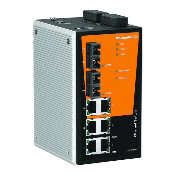
Package Checklist Your Ethernet Switch is shipped with the following items. If any of these items is missing or damaged, please contact your Weidmüller customer service for assistance. 1 Ethernet Switch of IE-SW-PL08M series Hardware Installation Guide (printed) ... - Page 3 Panel Layout of IE-SW-PL08M(T)-8TX 1. Grounding screw 2. Terminal block for power input PWR1/PWR2 and relay output 3. Heat dissipation orifices 4. Console port 5. DIP switches 6. Power input PWR1 LED 7. Power input PWR2 LED 8. Fault LED 9.
- Page 4 Panel Layout of IE-SW-PL08M(T)-6TX-2SC(S) 1. Grounding screw 2. Terminal block for power input PWR1/PWR2 and relay output 3. Heat dissipation orifices 4. Console port 5. DIP switches 6. Power input PWR1 LED 7. Power input PWR2 LED 8. Fault LED 9.
- Page 5 Panel Layout of IE-SW-PL08M(T)-6TX-2ST 1. Grounding screw 2. Terminal block for power input PWR1/PWR2 and relay output 3. Heat dissipation orifices 4. Console port 5. DIP switches 6. Power input PWR1 LED 7. Power input PWR2 LED 8. Fault LED 9.
-
Page 6: Mounting Dimensions (Unit = Mm)
Mounting Dimensions (unit = mm) DIN-Rail Mounting The aluminum DIN-Rail attachment plate should already be fixed to the back panel of the Ethernet Switch when you take it out of the box. If you need to reattach the DIN-Rail attachment plate, make sure the stiff metal spring is situated towards the top, as shown in the figures below. -
Page 7: Atex Information
Wall Mounting (with optional kit) For some applications, you will find it convenient to mount the Switch on the wall, as shown in the following figures. STEP 1: Remove the aluminum DIN-Rail attachment plate from the switch´s rear panel and then attach the wall mount plates as shown in the diagram at the right. -
Page 8: Wiring Requirements
Wiring Requirements WARNING The power for this product is intended to be supplied by a Listed Power Unit, with output marked LPS, and rated to deliver 12 to 48 VDC at a maximum of 600 mA. WARNING Safety First! Be sure to disconnect the power cord before installing and/or wiring your Ethernet Switch. -
Page 9: Wiring The Relay Contact
Wiring the Relay Contact The IE-SW-PL08M has two sets of relay output—relay 1 and relay 2. Each relay contact consists of two contacts of the terminal block on the IE-SW-PL08M´s top panel. Refer to the next section for detailed instructions on how to connect the wires to the terminal block connector, and how to attach the terminal block connector to the terminal block receptor. -
Page 10: Wiring The Digital Inputs
Wiring the Digital Inputs The IE-SW-PL08M switch has two sets of digital inputs, DI 1 and DI 2. Each DI consists of two contacts of the 6-pin terminal block connector on the Ethernet Switch´s top panel. Top and front views of the terminal block connector are shown below. - Page 11 RJ45 (8-pin) to RJ45 (8-pin) Cross-Over Cable Wiring 100BaseFX Ethernet Port Connection (Fiber) Remember to connect the Tx (transmit) port of device 1 to the Rx (receive) port of device 2, and the Rx (receive) port of device 1 to the Tx (transmit) port of device 2.
-
Page 12: Turbo Ring Dip Switch Settings
Turbo Ring DIP Switch Settings IE-SW-PL08M models are plug-and-play managed redundant Ethernet switches. The proprietary Turbo Ring protocol provides better network reliability and faster recovery time. Turbo Ring’s recovery time is less than 300 ms (Turbo Ring) or 20 ms (Turbo Ring V2) - compared to a 3- to 5-minute recovery time for commercial switches - decreasing the possible loss caused by network failures in an industrial setting. -
Page 13: Led Indicators
NOTE If you do not enable any of the IE-SW-PL08M Switches to be the Ring Master, the Turbo Ring protocol will automatically choose the switch with the smallest MAC address to be the Ring Master. If you accidentally enable more than one IE- SW-PL08M switch to be the Ring Master, these switches will auto-negotiate to determine which one will be the Ring Master. -
Page 14: Auto Mdi/Mdi-X Connection
Blinking When the Turbo Chain is down. When the coupling function at the switch is disabled or is set as a Member of a Turbo Chain TP port’s 10 Mbps link is active (TP) Blinking Data is being transmitted at 10 Mbps. GREEN Bottom LED of RJ-45 Port... - Page 15 Group 1,2,3,9 Forwarding and 148.810 pps Filtering Rate Processing Type Store and Forward Flow Control IEEE802.3x flow control, back pressure flow control Interface 10/100BaseT(X) auto negotiation speed, F/H duplex RJ45 Ports mode, and auto MDI/MDI-X connection Fiber Ports 100BaseFX ports (SC/ST-Duplex connector) Console RS-232 (RJ45) LED Indicators...
- Page 16 Power Input Voltage 12/24/48 V DC, 2 redundant inputs Input Current IE-SW-PL08M(T)-8TX: max. 0.22 A (@ 24 V) IE-SW-PL08M(T)-6TX-2SC/2ST/2SCS: max. 0.3 A 12/24/48 VDC, 0.62/0.3/0.16 A Rating Relay output 24 VDC/1 A (Resistive), Class 2 Connection Two removable 6-pin terminal blocks Overload Current Present Protection...
- Page 17 WARNING This equipment is intended to be used in a restricted access location. HOT SURFACE!! Before touching it, special attention or protection is required. Weidmüller gives a 5 year warranty on this product in accordance with the warranty terms as described in the general conditions of sale of the Weidmüller company which has sold the products to you.
Need help?
Do you have a question about the Premium Line IE-SW-PL08M Series and is the answer not in the manual?
Questions and answers