Summary of Contents for Weidmüller Value Line IE-SW-VL05M Series
Page 1
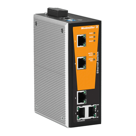
Managed Fast Ethernet Switches Value Line IE-SW-VL05M Series (from product Rev. 2.0.0) IE-SW-VL08MT-8TX/6TX (from product Rev. 2.0.0) IE-SW-VL08MT-5TX (from product Rev. 1.5.0) Hardware Installation Guide Seventh Edition, February 2019 1243340000/06/02.19 Important note: This document, the detailed user manual, additional product information, configuration tool and latest firmware can be downloaded using following link: http://www.weidmueller.com...
Overview The IE-SW-VL05/08M series are managed Fast Ethernet switches with 5-port or 8-ports in various copper and fiber variants. In addition, the built-in smart alarm function helps system maintainers monitor the health of your Ethernet network. Package Checklist Your Ethernet switch is shipped with the following items. If any of these items is missing or damaged, please contact your Weidmüller customer service for assistance.
Page 3
Panel Layouts of IE-SW-VL08MT-8TX and IE-SW-VL05M(T)-5TX Device description: 1. Grounding screw 2. Terminal block for power input PWR1/PWR2 and relay output 3. Heat dissipation orifices 4. Console port 5. DIP switches 6. Power input PWR1 LED 7. Power input PWR2 LED 8.
Page 4
Panel Layouts of IE-SW-VL08MT-6TX-2SCS and IE-SW-VL05M(T)-3TX-2SC Note: The appearance of the IE-SW-VL08MT-6TX- 2SC is identical to that of the IE-SW- VL08MT-6TX-2SCS. Device description: Grounding screw 2. Terminal block for power input PWR1/PWR2 and relay output 3. Heat dissipation orifices 4. Console port 5.
Page 5
Panel Layouts of IE-SW-VL08MT-6TX-2ST and IE-SW-VL05M(T)-3TX-2ST Device description: Grounding screw Terminal block for power input PWR1/PWR2 and relay output Heat dissipation orifices Console port DIP switches Power input PWR1 LED Power input PWR2 LED Fault LED MSTR/HEAD: LED indicator 10. CPLR/TAIL: LED indicator 11.
Page 6
Panel Layout of IE-SW-VL08MT-5TX-3SC IE-SW-VL08MT-5TX-3SC Front Panel View Note: The appearance of the IE-SW-VL08MT-5TX-1SC-2SCS is identical to that of the IE-SW-VL08MT-5TX-3SC Device description: Grounding screw Terminal block for power input PWR1/PWR2 and relay output Console port DIP switches Top Panel View Heat dissipation orifices Power input PWR1 LED Power input PWR2 LED...
Mounting Dimensions Units: mm (in) DIN-Rail Mounting The aluminum DIN-Rail attachment plate should already be fixed to the back panel of the IE-SW-VL05/08M switch when you take it out of the box. If you need to reattach the DIN-Rail attachment plate, make sure the stiff metal spring is situated towards the top, as shown in the following figures.
Wall Mounting (optional) For some applications, you will find it convenient to mount the Ethernet switch on the wall, as shown in the following figures. STEP 1: Remove the aluminum DIN-Rail attachment plate from the switch rear panel, and then attach the wall mount plates as shown in the diagram at the right.
ATEX Information 1. Certificate number DEMKO 18 ATEX 2137X 2. Ambient range: -40°C ≤ Tamb ≤ 75°C 3. Certification string: IE-SW-VL08MT-8TX: Ex nA nC IIC T4 Gc IE-SW-VL08MT-6TX-2SC/2ST/2SCS: Ex nA nC op is IIC T4 Gc 4. Standards covered: EN 60079-0:2012+A11:2013, EN 60079-15:2010, EN 60079-28:2015 5.
Grounding the Ethernet Switch Grounding and wire routing help limit the effects of noise due to electromagnetic interference (EMI). Run the ground connection from the ground screw to the grounding surface prior to connecting devices. A 4 mm conductor must be used when connection to the external grounding screw is utilized.
STEP 1: Insert the negative/positive DC wires into the V-/V+ terminals, respectively. STEP 2: To keep the DC wires from pulling loose, use a small flat-blade screwdriver to tighten the wire-clamp screws on the front of the terminal block connector. STEP 3: Insert the plastic terminal block connector prongs into the terminal block receptor, which is located on the Switch´s top...
RJ45 (8-pin) to RJ45 (8-pin) Cross-Over Cable Wiring 100BaseFX Ethernet Port Connection (Fiber) Remember to connect the Tx (transmit) port of device 1 to the Rx (receive) port of device 2, and the Rx (receive) port of device 1 to the Tx (transmit) port of device 2.
Relay Contact The Ethernet switch has one Relay Contact located on the top panel. For detailed instructions on how to connect the Relay Contact power wires to the two middle contacts of the 6-contact terminal block connector, see the Wiring the Relay Contact section. A typical scenario would be to connect the fault circuit to a warning light located in the control room.
“Turbo Ring” DIP Switch Settings DIP 1 DIP 2 DIP 3 DIP 4 Reserved for ON: Enables ON: Enables the ON: Activates future use. this Ethernet default “Ring DIP switches 1, Switch as the Coupling” ports. 2, 3 to configure Ring Master.
Power is not being supplied to power input PWR2. When (1) a relay warning event is triggered, (2) the switch is the Master of this Turbo Ring, and the Turbo Ring is broken, or (3) start-up failure. FAULT When a relay warning event is not triggered.
Page 17
Power Input Voltage 12/24/48 V DC (9.6 to 60 V DC), 2 redundant inputs IE-SW-VL05M series: 0.594 A/0.286 A/0.154 A @ 12/24/48 V Input Current IE-SW-VL08MT series: 0.61 A/0.3 A/0.16 A @ 12/24/48 V IE-SW-VL08MT-5TX-3SC/2SCS-1SC: 0.73 A/0.35 A/0.18 A @ 12/24/48 V Connection One removable 6-pin terminal block Overload Current...
Page 18
Database Telcordia (Bellcore), GB WARRANTY Time Period 5 years WARNING This equipment is intended to be used in a restricted access location. HOT SURFACE!! Before touching it, special attention or protection is required. Weidmüller gives a 5 year warranty on this product in accordance with the warranty terms as described in the general conditions of sale of the Weidmüller company which has sold the products to you.
Need help?
Do you have a question about the Value Line IE-SW-VL05M Series and is the answer not in the manual?
Questions and answers