Table of Contents
Advertisement
Quick Links
Managed Fast/Gigabit Ethernet
Switches Premium Line
IE-SW-PL10M Series
(from product Rev. 2.0.0)
Hardware Installation Guide
Sixth Edition, August 2018
1243400000/05/08.18
Important note:
This document, the detailed user manual, additional product
information, configuration tool and latest firmware can be
downloaded using following link:
http://www.weidmueller.com
► Select Product Catalogue
Select „Active Industrial Ethernet"
Select „PremiumLine managed Switches"
Select Product model
Click and expand section „Downloads"
Download needed software or documentation
Copyright Notice
Copyright 2018 Weidmüller Interface GmbH & Co. KG
All rights reserved.
Reproduction without permission is prohibited.
Advertisement
Table of Contents

Subscribe to Our Youtube Channel
Related Manuals for Weidmüller Premium Line IE-SW-PL10M Series


Summary of Contents for Weidmüller Premium Line IE-SW-PL10M Series
- Page 1 Managed Fast/Gigabit Ethernet Switches Premium Line IE-SW-PL10M Series (from product Rev. 2.0.0) Hardware Installation Guide Sixth Edition, August 2018 1243400000/05/08.18 Important note: This document, the detailed user manual, additional product information, configuration tool and latest firmware can be downloaded using following link: http://www.weidmueller.com ►...
-
Page 2: Package Checklist
Package Checklist Your Ethernet switch is shipped with the following items. If any of these items is missing or damaged, please contact your Weidmüller customer service for assistance. 1 Ethernet Switch of IE-SW-PL10M series Hardware Installation Guide (printed) RJ45 to DB9 console port cable Protective caps for unused ports Regarding further documentation like the manual please download it from the Weidmüller product catalouge as described on page 1. - Page 3 Brief Information for quick access to the Web interface The Web interface of the managed Switch can be accessed via IP address 192.168.1.110 and subnet mask 255.255.255.0 (Factory default value). Connect the PC to any port of the managed Switch and set the PC’s IP address to a free one of range 192.168.1.0 / 255.255.255.0 Start a web browser and enter the IP address of the...
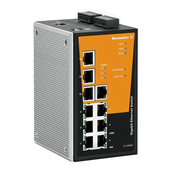
- Page 4 Panel Layout of IE-SW-PL10M-series 1) 1 to 7 10/100BaseT(X) ports 2) G1 10/100/1000BaseT(X) port 3) G2 IE-SW-PL10M(T)-3GT-7TX = 10/100/1000BaseT(X) port, IE-SW-PL10M(T)-1GT-2GS-7TX = 1000BaseSFP port 4) G3 IE-SW-PL10M(T)-3GT-7TX = 10/100/1000BaseT(X) port, IE-SW-PL10M(T)-1GT-2GS-7TX = 1000BaseSFP port 5) G1, G2, G3: LED indicators for 1000 Mbps ports 6) PWR1: LED for power input 1 7) PWR2: LED for power input 2...
-
Page 5: Mounting Dimensions
Mounting Dimensions Units: mm (inch) DIN-Rail Mounting The aluminum DIN-Rail clip should already be fixed to the back panel of the Ethernet Switch when you take it out of the box. If you need to reattach the DIN-Rail clip, make sure the stiff metal spring is situated towards the top, as shown in the following figures. -
Page 6: Wall Mounting (Optional)
Wall Mounting (optional) For some applications, you will find it convenient to mount the Ethernet switch on the wall, as shown in the following figures. STEP 1: Remove the aluminum DIN-Rail attachment plate from the switch rear panel, and then attach the wall mount plates as shown in the diagram at the right. -
Page 7: Wiring Requirements
Wiring Requirements WARNING Do not disconnect modules or wires unless the power supply has been switched off or the area is known to be non- hazardous. The devices may only be connected to the supply voltage shown on the type plate. The devices are designed for operation with a Safety Extra- Low Voltage. -
Page 8: Wiring The Redundant Power Inputs
Grounding the Ethernet Switch Grounding and wire routing help limit the effects of noise due to electromagnetic interference (EMI). Run the ground connection from the ground screw to the grounding surface prior to connecting devices. ATTENTION This product is intended to be mounted to a well-grounded mounting surface, such as a metal panel. -
Page 9: Wiring The Digital Inputs
Wiring the Digital Inputs The Ethernet Switch has two sets of digital inputs, DI 1 and DI 2. Each DI consists of two contacts of the 6-pin terminal block connector on the Switch´s top panel. The top and front views of one of the terminal block connectors are shown here. - Page 10 10/100BaseT(X) Ethernet Port Connection The 10/100BaseT(X) ports located on the Switch´s front panel are used to connect to Ethernet-enabled devices. Most users configure these ports for Auto MDI/MDI-X mode, in which case the port’s pinouts are adjusted automatically depending on the type of Ethernet cable used (straight-through or cross-over), and the type of device (NIC-type or HUB/Switch-type) connected to the port.
- Page 11 1000BaseT Ethernet Port Connection 1000BaseT data is transmitted on differential TRD+/- signal pairs over copper wires. MDI/MDI-X Port Pinouts Signal TRD(0)+ TRD(0)- TRD(1)+ TRD(2)+ TRD(2)- TRD(1)- TRD(3)+ TRD(3)- 1000BaseSFP (mini-GBIC) Fiber Port The Fiber optic ports on the IE-SW-PL10M(T)-1GT-2GS-7TX are SFP type slots, which require 1000BaseSFP mini-GBIC fiber transceivers to work properly.
-
Page 12: Turbo Ring Dip Switch Settings
Turbo Ring DIP Switch Settings Switches of IE-SW-PL10M series are managed Ethernet switches that offer redundancy. The proprietary Turbo Ring protocol provides better network reliability and faster recovery time. Turbo Ring’s recovery time is less than 300 ms (Turbo Ring) or 20 ms (Turbo Ring V2) - compared to a 3- to 5-minute recovery time for commercial switches - decreasing the possible loss caused by network failures in an industrial setting. -
Page 13: Led Indicators
NOTE You must enable the Turbo Ring function first (DIP 4) before using the DIP switches to activate the Master and Coupler functions. NOTE If you do not enable any of the IE-SW-PL10M switches to be the Ring Master, the Turbo Ring protocol will automatically choose the switch with the smallest MAC address to be the Ring Master. -
Page 14: Specifications
When the switch coupling function is enabled to form a back-up path, or when it's set as the Tail of the Turbo Chain. CPLR/ Blinking When the Turbo Chain is down. GREEN TAIL When the switch disables the coupling function, or is set as the Member of the Turbo Chain. - Page 15 Power Input Voltage 24 VDC (12 to 45 VDC), 2 redundant inputs Input Current IE-SW-PL10M(T)-3GT-7TX: 0.48 A (@24V) IE-SW-PL10M(T)-1GT-2GS-7TX: 0.38 A Connection Two removable 6-pin terminal blocks Overload Current Present Protection Reverse Polarity Present Protection Mechanical Housing Metal, IP30 protected Dimensions 80.5 ×...
- Page 16 WARNING This equipment is intended to be used in a restricted access location. HOT SURFACE!! Before touching it, special attention or protection is required. Weidmüller gives a 5-year warranty on this product in accordance with the warranty terms as described in the general conditions of sale of the Weidmüller company which has sold the products to you.
Need help?
Do you have a question about the Premium Line IE-SW-PL10M Series and is the answer not in the manual?
Questions and answers