Table of Contents
Advertisement
Quick Links
Unmanaged Gigabit PoE
Switches Basic Line
IE-SW-BL05-4GTPoE Series
Hardware Installation Guide
Second Edition, May 2016
1516590000/01/05.16
Important note:
This document and additional product information can be
downloaded using following link:
http://www.weidmueller.com
► Select Product Catalogue
Select „Industrial Ethernet active"
Select „PoE unmanaged Switches"
Select Product model
Click and expand section „Downloads"
Download needed documentation
Copyright Notice
Copyright 2016 Weidmüller Interface GmbH & Co. KG
All rights reserved.
Reproduction without permission is prohibited.
Advertisement
Table of Contents

Subscribe to Our Youtube Channel
Related Manuals for Weidmüller Basic Line IE-SW-BL05-4GTPoE Series


Summary of Contents for Weidmüller Basic Line IE-SW-BL05-4GTPoE Series
- Page 1 Unmanaged Gigabit PoE Switches Basic Line IE-SW-BL05-4GTPoE Series Hardware Installation Guide Second Edition, May 2016 1516590000/01/05.16 Important note: This document and additional product information can be downloaded using following link: http://www.weidmueller.com ► Select Product Catalogue Select „Industrial Ethernet active“ ...
-
Page 2: Package Checklist
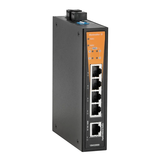
Overview The IE-SW-BL05-4GTPoE series consists of rugged industrial 5-port Gigabit PoE switches for environments that fall under the pollution degree 2 category The industrial Ethernet switches support IEEE 802.3, IEEE 802.3u, IEEE 802.3x with 10/100/1000M, full/half-duplex, MDI/MDIX auto-sensing, IEEE 802.3z with 1000M full-duplex (SFP model), and IEEE 802.3af/IEEE 802.3at PoE standards. - Page 3 Panel Layout of IE-SW-BL05-4GTPoE series IE-SW-BL05-1GS-4GTPoE IE-SW-BL05-1GT-4GTPoE Front Panel View Front Panel View Device description: 1. Terminal blocks for P1/P2 power inputs 2. Power input P1 LED 3. Power input P2 LED 4. PoE status LED 5. 10/100/1000Base-T(X) PoE ports (port 2,3,4,5) 6.
-
Page 4: Mounting Dimensions (Unit = Mm)
Mounting Dimensions (unit = mm) DIN-Rail Mounting The aluminum DIN-Rail attachment plate should already be fixed to the back panel of the switch when you take it out of the box. If you need to reattach the DIN-Rail attachment plate, make sure the stiff metal spring is situated towards the top, as shown in the figures below. -
Page 5: Wall Mounting (Optional)
Wall Mounting (optional) For some applications, you will find it convenient to mount the IE-SW- BL05 switch on the wall, as shown in the following figures. STEP 1: Remove the aluminum DIN-Rail attachment plate from the switch´s rear panel, and then attach the wall mount plates as shown in the diagram at the right. -
Page 6: Wiring Requirements
Wiring Requirements WARNING Safety First Turn the power off before disconnecting modules or wires. The correct power supply voltage is listed on the product label. Check the voltage of your power source to make sure that you are using the correct voltage. Do NOT use a voltage greater than what is specified on the product label Calculate the maximum possible current in each power wire and common wire. -
Page 7: Communication Connections
STEP 1: Insert the negative/positive DC wires into the V-/V+ terminals. STEP 2: To keep the DC wires from pulling loose, use a small flat-blade screwdriver to tighten the wire-clamp screws on the front of the terminal block connector. STEP 3: Insert the plastic terminal block connector prongs into the terminal block receptor, which is located on Switch’s top panel. -
Page 8: Poe Ethernet Port Connection
1000BaseT RJ45 Pinouts MDI-X BI_DA+ BI_DB+ BI_DA- BI_DB- BI_DB+ BI_DA+ BI_DC+ BI_DD+ BI_DC- BI_DD- BI_DB- BI_DA- BI_DD+ BI_DC+ BI_DD- BI_DC- PoE Ethernet Port Connection PoE ports located on the switch’s front panel are used to connect to PoE-enabled devices. The pinout follows the “Alternative A, MDI mode”... -
Page 9: Redundant Power Inputs
RJ45 (8-pin) to RJ45 (8-pin) Cable Wiring NOTE If the PD only supports PoE MDI mode (V+, V+, V-, V- for pins 1, 2, 3, 6), choose a cross-over Ethernet cable to connect the PD and the switch. If the PD only supports PoE MDI-X mode (V-, V-, V+, V+ for pins 1, 2, 3, 6), choose a straight-through Ethernet cable between the PD and the Switch. -
Page 10: Dip Switch Settings
DIP Switch Settings The default setting for each DIP Switch is OFF. The following table explains the effect of setting the DIP Switches to the ON positions. IE-SW-BL05-1GT-4GTPOE IE-SW-BL05-1GS-4GTPOE (Copper Model) (SFP Model) DIP Switch Setting Description Enable broadcast storm protection OFF Disable broadcast storm protection Enable jumbo frame function Jumbo... -
Page 11: Led Indicators
LED Indicators The front panel of the Switches contain several LED indicators. The function of each LED is described in the following table. Color State Description Power is being supplied to power input PWR1 AMBER Power is not being supplied to power input P1. -
Page 12: Auto Mdi/Mdi-X Connection
Auto MDI/MDI-X Connection The Auto MDI/MDI-X function allows users to connect the Switch’s 10/100/1000BaseT(X) ports to any kind of Ethernet device, without needing to pay attention to the type of Ethernet cable being used for the connection. This means that you can use either a straight-through cable or cross-over cable to connect the Ethernet Switch to Ethernet devices. -
Page 13: Total Power Budget
Total Power Budget For the total power budget, the switch will provide 62 W at 12 to 17 VDC input, 120 W at 18 to 35 VDC input, and 144 W at 36 to 57 VDC input. The total power budget is the total amount of reserved PoE power based on the PoE class of the PoE device. - Page 14 Power: PWR1, PWR2 TP Port: 10/100/1000M LED Indicators Fiber Port: 100/1000M PoE Ports: PoE+ for Port 2,3,4,5 Broadcast storm protection, Jumbo Frame, DIP Switches 802.3az, Standard PoE/PoE High Power, 100/1G SFP Total Power Budget 62 W @ 12 VDC (12 to 17 VDC) 120 W @ 24 VDC (18 to 35 VDC) 144 W @ 48 VDC (36 to 57 VDC) PoE Output Voltage...
- Page 15 CISPR 22, FCC Part 15B Class A IEC 61000-4-2 ESD: Contact: 6 kV; Air: 8 kV IEC 61000-4-3 RS: 80 MHz to 1 GHz: 10 V/m IEC 61000-4-4 EFT: Power: 2 kV; Signal: 2 kV IEC 61000-4-5 Surge: Power: 2 kV; Signal: 2 kV IEC 61000-4-6 CS: 10 V IEC 61000-4-8 Standards and Certifications...
Need help?
Do you have a question about the Basic Line IE-SW-BL05-4GTPoE Series and is the answer not in the manual?
Questions and answers