Table of Contents
Advertisement
Quick Links
Advertisement
Table of Contents

Related Manuals for DTK PAM-0035S


Summary of Contents for DTK PAM-0035S
- Page 1 DTK PAM-0035S P54C PCI Mainboard User's Manual...
- Page 2 ABOUT THIS GUIDE This guide contains instructions for configuring and installing the mainboard. Chapter 1, Introduction, acquaints user with the special features of the mainboard. Chapter 2, Hardware Configuration, gives information on configuring memory and setting the mainboard's jumpers. Brief sections on installing memory. Chapter 3, Mainboard Installation, is an overview of how to install the mainboard in a system.
- Page 3 UNPACKING THE MAINBOARD The Mainboard comes packed in a sturdy cardboard shipping carton. The carton contains: The Mainboard PCI IDE Driver Diskette 40-pin Hard Disk Cable 34-pin Floppy Disk Cable 25-pin Serial & 15-pin Game Port Cable 9-pin Serial & 25-pin Parallel Port Cable This User's Guide Note: Do not remove the mainboard from its original packing until ready to install.
-
Page 4: Table Of Contents
CONTENTS CHAPTER 1 INTRODUCTION KEY FEATURES MAINBOARD COMPONENTS PCI LOCAL BUS SPECIAL FEATURES CHAPTER 2 HARDWARE CONFIGURATION JUMPER AND MEMORY BANK LOCATIONS JP01 - CPU TYPE SELECTION S0-S2, JP0 - CPU CLOCK SELECTION CPU INSTALLATION CACHE CONFIGURATION 2.5.1 UPGRADING CACHE 2.5.2 CACHE SIZE AND MEMORY LOCATIONS 2.5.3... - Page 5 CHAPTER 3 MAINBOARD INSTALLATION COMPONENTS INSTALLING THE MAINBOARD CONNECTION THE MAINBOARD 3.3.1 CONNECTION LOCATIONS CONNECTORS 3.4.1 J1 - CPU FAN POWER CONNECTOR 3.4.2 J2 - HARD DISK LED CONNECTOR 3.4.3 J3 - KEYLOCK & POWER LED CONNECTOR 3.4.4 J4 - SPEAKER CONNECTOR 3.4.5 J5 - TURBO SWITCH CONNECTOR 3.4.6...
- Page 6 CHAPTER 4 AWARD BIOS SETUP ENTERING SETUP CONTROL KEYS GETTING HELP THE MAIN MENU 4.4.1 STANDARD CMOS SETUP MENU 4.4.2 BIOS FEATURES SETUP MENU 4.4.3 CHIPSET FEATURES SETUP MENU 4.4.4 POWER MANAGEMENT SETUP MENU 4.4.5 PCI CONFIGURATION SETUP MENU 4.4.6 LOAD BIOS DEFAULTS MENU 4.4.7 LOAD SETUP DEFAULTS MENU...
-
Page 7: Introduction
CHAPTER 1 INTRODUCTION The mainboard is a 2/3 bady AT size high-performance mainboard that provides with basic elements on which to build an advanced computer. The mainboard running at 75MHz, 90MHz, 100MHz, 120MHz or up to 133MHz, supporting the Intel Pentium CPU. KEY FEATURES The advanced features of the mainboard include: Intel Pentium CPU, Cyrix M1 support up to 75, 90, 100, 120 or 133MHz... - Page 8 Chapter 1 Easy upgrade CPU speed by alter jumpers only. System & video Bios Shadow, optional caching of shadowed system & video BIOS. Provide FDD channels which support 360K, 720K, 1.2M & 1.44M Floppy Disks, two 16550 compatible UARTs, one parallel port with EPP/ECP mode, and one joystick port.
-
Page 9: Mainboard Components
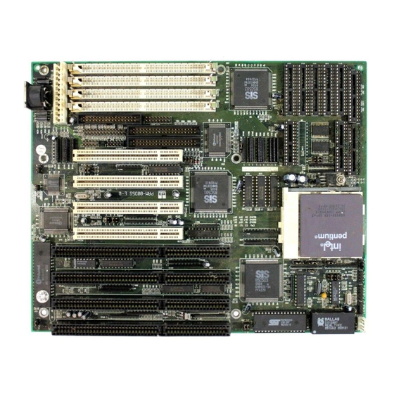
Introduction MAINBOARD COMPONENTS This section gives a brief description of key components on the mainboard. Refer to Fig 1 for component locations. Fig 1 Key Components of the Mainboard... -
Page 10: Pci Local Bus Special Features
Chapter 1 PCI LOCAL BUS SPECIAL FEATURES PCI (Peripheral Component Interconnect) Local-Bus is the latest Local Bus Standard which adapts the high performance and supports the future standard on the PC industry. Four PCI slots are provided on the mainboard support up to four Bus Master devices. -
Page 11: Hardware Configuration
CHAPTER 2 HARDWARE CONFIGURATION This chapter describes how to set the mainboard jumpers for cache memory and display type, and how to install memory modules. Before beginning the configuration, user should take the following precautions: Turn off the power supply, and unplug the power cord before begin. Unplug all cables that connect the mainboard to any external devices. -
Page 12: Jp01 - Cpu Type Selection
Chapter 2 JP01 - CPU TYPE SELECTION The mainboard can support processor at differenct speed. Various jumper are required to setup for installing different CPU. Refer to Fig 2 for jumper location, and set the jumper according to the following table: JP01 -- CPU Type Selection Table 1: CPU Type Configuration S0-S2, JP0 - CPU CLOCK SELECTION... -
Page 13: Cpu Installation
Hardware Configuration CPU INSTALLATION The mainboard has a socket that can support Pentium CPU. See Fig 1 in Chapter 1 for the socket's location. Install the CPU as follows: Caution: Static electricity can damage the processor. Plug the CPU into the socket, with the notch corner aligned. Fig 3 Installing a CPU CONFIGURATION The special feature of the mainboard is a built-in direct-mapped cache controller... -
Page 14: Upgrading Cache
Chapter 2 2.5.1 UPGRADING CACHE The mainboard is available with an optional 256KB, 512KB, or 1MB cache memory on-board. User can upgrade cache memory by installing additional SRAM (Static Random Access Memory) chips in sockets U10-U17; U9. The speed of the SRAM chips needed depends on the clock speed of the microprocessor: 75,90,100,120,133MHz CPU requires 15ns (tag and data) SRAM chips. -
Page 15: Cache Chip Sockets And Jumper Locations
Hardware Configuration 2.5.3 CACHE CHIP SOCKETS AND JUMPER LOCATIONS The diagram below describes the location of the cache chip sockets and cache jumpers. Fig 4 Cache Jumper and Socket Locations 2.5.4 JP7-JP9 - CACHE JUMPER SETTING Cache memory is configured using jumpers, JP7, JP8, & JP9. The following table summarize the possible configuration. -
Page 16: Installing Cache Chips
Chapter 2 2.5.5 INSTALLING CACHE CHIPS Install cache chips on the mainboard as follows: Caution: Static electricity can damage a cache chip. Review the section on static electricity precautions at the beginning of this manual, and make sure that power to the mainboard is off. Align the chip so that the notched corner of the chip matches the notched corner of the socket. -
Page 17: Jp5 - Cpu Pipeline Mode Selection
Hardware Configuration JP5 - CPU PIPELINE MODE SELECTION JP5 is used to enable or disable the pipeline mode of CPU. Refer to Fig 2 for the location, and set the jumper as below. JP5 -- CPU Pipeline Mode Selection Table 6 JP6 - CPU INTERNAL CACHE WRITE BACK/ WRITE THROUGH SELECTION JP6 is used to select the CPU Internal Cache to be Write Back or Write Through. -
Page 18: Jp12 - Video Selection
Chapter 2 JP12 - VIDEO SELECTION Please set JP12 for Mono or Color Video Display. Refer to Fig 2 for the location. JP12 -- Video Selection Table 8 2.10 JP1 - DISCHARGE CMOS RAM JP1 is used to clear the content of the CMOS RAM in the RTC chip DS12887A. Refer to Fig 2 for the location. -
Page 19: Jp2, Jp3 - Eprom Type Selection
Hardware Configuration 2.11 JP2, JP3 - EPROM TYPE SELECTION JP2, JP3 are for EPROM Type Selection. Refer to Fig 2 for the location. JP2, JP3 -- EPROM Type Selection Table 10 2.12 JP18 - PARALLEL PORT IRQ SELECTION JP18 is for Parallel Port IRQ selection. Refer to Fig 2 for the location. JP18 -- Parallel Port IRQ Selection Table 11... -
Page 20: Jp22, Jp23 - Parallel Port Setting And Ecp Dma Selection
Chapter 2 2.13 JP22, JP23 - PARALLEL PORT SETTING AND ECP DMA SELECTION JP22, JP23 are for Parallel Port Setting and ECP DMA selection. Refer to Fig 2 for the location. JP22, JP23 -- Parallel Port Setting Table 12 2.14 MEMORY INSTALLATION The mainboard lets user add system memory via SIMM sockets on the mainboard. - Page 21 Hardware Configuration The mainboard supports the following configurations: SIM 1 SIM 2 SIM 3 SIM 4 Memory Size NONE NONE NONE NONE NONE NONE 10MB 12MB NONE NONE 16MB 16MB 18MB 20MB 24MB NONE NONE 32MB 32MB TO BE CONTINUE... Table 13A: On-board Memory Configuration...
- Page 22 Chapter 2 SIM 1 SIM 2 SIM 3 SIM 4 Memory Size 34MB 36MB 40MB 48MB NONE NONE 64MB 64MB 66MB 68MB 72MB 80MB 96MB 128MB Table 13B: On-board Memory Configuration...
-
Page 23: Installing Simm
Hardware Configuration 2.14.1 INSTALLING SIMM Install a SIMM in a memory socket as follows: Caution: Static electricity can seriously damage SIMM modules. Review the section on static electricity precautions at the beginning of this manual. Align the SIMM module so that the pin-1 marking on the module corresponds to the socket pin-1 marking. - Page 24 Chapter 2 To fill a bank, repeat steps 1 through 4 until the sockets in each bank contain SIMMs. After installing memory, run BIOS Setup to indicate to the system for how much memory the user has installed.
-
Page 25: Mainboard Installation
CHAPTER 3 MAINBOARD INSTALLATION Once the mainboard's hardware has been configured, the user is now ready to install the mainboard into the system chassis. This chapter describes what are needed to assemble an advanced computer system based on the mainboard. COMPONENTS The following components are recommended: Case with standard chassis and hardware. -
Page 26: Installing The Mainboard
Chapter 3 INSTALLING THE MAINBOARD Before starting, check the location of the mounting holes in the case and on the mainboard. Caution: Static electricity can damage the mainboard. Install the mainboard as follows: Review the section on static electricity precautions at the beginning of this manual. -
Page 27: Connection The Mainboard
Mainboard Installation CONNECTION THE MAINBOARD Once the mainboard has been fastened into the system case, the next step is to connect the internal cables. The internal cables are wire leads with plastic female connectors that attach to the connectors. A description of each connector and its connector pins follows. -
Page 28: Connectors
Chapter 3 CONNECTORS 3.4.1 J1 - CPU FAN POWER CONNECTOR J1 connects to the cooling fan of the CPU. Description +12V Ground Ground Table 14 3.4.2 J2 - HARD DISK LED CONNECTOR J2 connects to the HDD LED in front of the system case. Description + Anode - Cathode... -
Page 29: J3 - Keylock & Power Led Connector
Mainboard Installation 3.4.3 J3 - KEYLOCK & POWER LED CONNECTOR J3 is a keylock connector that enables and disables the keyboard and the Power- LED on the case. Description LED Power Not Used Ground Keyboard Inhibit Ground Table 16 3.4.4 J4 - SPEAKER CONNECTOR Attached the system speaker to connector J4. -
Page 30: J5 - Turbo Switch Connector
Chapter 3 3.4.5 J5 - TURBO SWITCH CONNECTOR J5 connects to the Turbo switch, which is used to select the mainboard's clock speed. Table 18 3.4.6 J6 - TURBO LED CONNECTOR J6 is usually connected to a Turbo LED on front of the system case. Description - Cathode + Anode... -
Page 31: J7 - Hardware Reset Connector
Mainboard Installation 3.4.7 J7 - HARDWARE RESET CONNECTOR Attach the Hardware Reset Switch cable to this connector. The Hardware Reset restarts the system. Table 20 3.4.8 J8 - ON BOARD PCI IDE 1 HDD CONNECTOR J8 is a 40-pin IDE Hard Disk connector. It is assigned as Channel 1 for Secondary Hard Disk Controller connector. -
Page 32: J10 - Keyboard Connector
Chapter 3 3.4.10 J10 - KEYBOARD CONNECTOR A standard five-pin female DIM keyboard connector is located at the rear of the keyboard. Plug the jack on the keyboard cable into this connector. Description Keyboard Clock Keyboard Data Spare Ground +5V DC Table 21 3.4.11 J11 - POWER SUPPLY CONNECTOR The power supply connector has twelve-pin male header connectors. -
Page 33: J12 - On Board Com1 Connector
Mainboard Installation 3.4.12 J12 - ON BOARD COM1 CONNECTOR J12 is a 10-pin COM1 connector. It is assigned as COM1/COM3 for serial port. Refer to Fig 3 for its location. 3.4.13 J13 - ON BOARD COM2 CONNECTOR J12 is a 10-pin COM2 connector. It is assigned as COM2/COM4 for serial port. -
Page 34: Harddisk Installation
Chapter 3 HARDDISK INSTALLATION The mainboard on-board built-in the PCI IDE Controller which supports 2 enhanced IDE channels with Primary IDE address on 1F0-1F7, 3F6, 3F7; and Secondary IDE address on 170-177, 376, 377. Please following the steps shown below to process installation. 2 Drives System: Case A: Set Drive C: to Master;... -
Page 35: System Assembly Overview
Mainboard Installation Perform system CMOS setup, enter correct drive geometry information. For 4 HDDs system, there is no need to setup the drive geometry information for Drives E: and F:. Install the Device Driver Please refer to the README file in Driver Diskette for detail installation procedures to be used in various kind of operating system (DOS, Windows 3.1, Windows NT, OS/2 2.XX, Novel 3.1X/4.0X). - Page 36 Chapter 3 Display: Connect the display cable to the Video Card, and the display's power cord into a power outlet. Case: Slide on the case cover and fasten its screws. Connect the power cord to the power supply and plug it into a wall outlet. Put the boot disk into drive A: and turn on the power.
-
Page 37: Award Bios Setup
CHAPTER 4 AWARD BIOS SETUP Award's BIOS ROM has a built-in Setup program that allows users to modify the basic system configuration. This type of information is stored in battery-backed RAM so that it retains the Setup information when the power is turned off. ENTERING SETUP Power on the computer and press <Del>... -
Page 38: Control Keys
Chapter 4 CONTROL KEYS Up arrow: Move to previous item Down arrow: Move to next item Left arrow: Move to the item in the left hand Right arrow: Move to the item in the right hand Esc key: Main Menu -- Quit and not save changes into CMOS Status Page Setup Menu and Option Page Setup Menu -- Exit current page and return to Main Menu PgUp key:... -
Page 39: The Main Menu
Award BIOS Setup THE MAIN MENU Once you enter Award BIOS CMOS Setup Utility, the Main Menu will appear on the screen. The Main Menu allows you to select from ten setup functions and two exit choices. Use arrow keys to select among the items and press <Enter> to accept or enter the sub-menu. -
Page 40: Standard Cmos Setup Menu
Chapter 4 4.4.1 STANDARD CMOS SETUP MENU The items on Standard CMOS Setup Menu are divided into 10 categories. Each category includes no, one or more than one setup items. Use the arrow keys to highlight the item and then use the <PgUp> or <PgDn> keys to select the value you want in each item. -
Page 41: Bios Features Setup Menu
Award BIOS Setup 4.4.2 BIOS FEATURES SETUP MENU ROM PCI/ISA BIOS (2A5IAG32) BIOS FEATURES SETUP AWARD SOFTWARE, INC. Virus Warning : Disabled Video BIOS Shadow : Enabled CPU Internal Cache : Enabled C8000-CBFFF Shadow: Disabled External Cache : Enabled CC000-CFFFF Shadow: Disabled Quick Power On Self Test : Disabled D0000-D3FFF Shadow: Disabled Boot Sequence... -
Page 42: Chipset Features Setup Menu
Chapter 4 4.4.3 CHIPSET FEATURES SETUP MENU ROM PCI/ISA BIOS (2A5IAG32) CHIPSET FEATURES SETUP AWARD SOFTWARE, INC. Auto Configuration : Enabled PCI Clock Frequency : CPUCLK/1.5 CPU/PCI Burst Mem. Write: Disabled L1 Cache Update Mode : WB CPU/PCI Post Mem. Write: Disabled L2 Cache Update Mode : WB ISA Bus Clock Frequency : PCICLK/3... -
Page 43: Power Management Setup Menu
Award BIOS Setup 4.4.4 POWER MANAGEMENT SETUP MENU ROM PCI/ISA BIOS (2A5IAG32) POWER MANAGEMENT SETUP AWARD SOFTWARE, INC. Power Management : Max Saving VGA Activity : Disable PM Control by APM : Yes IRQ3 (COM 2) : Enable Video Off Option : Suspend->Off IRQ4 (COM 1) : Enable... -
Page 44: Pci Configuration Setup Menu
Chapter 4 4.4.5 PCI CONFIGURATION SETUP MENU ROM PCI/ISA BIOS (2A5IAG32) BIOS FEATURES SETUP AWARD SOFTWARE, INC. Slot 1 Using INT# : Auto Onboard PCI/IDE Chip : Enabled Slot 2 Using INT# : Auto Slot 3 Using INT# : Auto Onboard FDD Controller : Enabled Slot 4 Using INT# : Auto Onboard Serial Port 1... -
Page 45: Load Bios Defaults Menu
Award BIOS Setup 4.4.6 LOAD BIOS DEFAULTS MENU When you select this function, the following message will appear at the centre of the screen to assist you to load BIOS defaults (except Standard CMOS Setup). Load BIOS Defaults (Y/N)? 4.4.7 LOAD SETUP DEFAULTS MENU When you select this function, the following message will appear at the centre of the screen to assist you to load Setup defaults (except Standard CMOS Setup). -
Page 46: Ide Hdd Auto Detection Menu
Chapter 4 4.4.9 IDE HDD AUTO DETECTION MENU This function will automatically detect the information of the Hard Disk, and list them for your reference. ROM PCI/ISA BIOS (2A5IAG32) CMOS SETUP UTILITY AWARD SOFTWARE, INC. CYLS. HEADS PRECOMP LANDZONE SECTORS Drive C : ( Select Drive C Option (N=Skip) : N OPTIONS SIZE CYLS. -
Page 47: Hdd Low Level Format Menu
Award BIOS Setup 4.4.10 HDD LOW LEVEL FORMAT MENU Three utilities are provided in the HDD Low Level Format menu: (1) SELECT DRIVE (2) BAD TRACK LIST (3) PREFORMAT Hard Disk Low Level Format Utility BAD TRACKS TABLE NO. CYLS HEAD SELECT DRIVE BAD TRACK LIST PREFORMAT... - Page 48 Chapter 4 Hard Disk Low Level Format Utility BAD TRACKS TABLE NO. CYLS HEAD SELECT DRIVE BAD TRACK LIST PREFORMAT Auto scan bad track Add bad track Modify bad track Delete bad track Clear bad track table DRIVE : C CYLINDER : 0 HEAD : 0 984.
- Page 49 Award BIOS Setup Hard Disk Low Level Format Utility BAD TRACKS TABLE NO. CYLS HEAD SELECT DRIVE BAD TRACK LIST PREFORMAT Interleave (1-8) : 0 (0 for auto detect) Auto scan bad track : N START : N DRIVE : C CYLINDER : 0 HEAD : 0 984.
-
Page 50: Save & Exit Setup Menu
Chapter 4 4.4.11 SAVE & EXIT SETUP MENU When you select this function, the following message will appear at the centre of the screen to assist you to Save data to CMOS and Exit the Setup. SAVE to CMOS and EXIT (Y/N)? 4.4.12 EXIT WITHOUT SAVING MENU When you select this function, the following message will appear at the centre of the screen to assist you to Abandon all Data and Exit Setup. -
Page 51: Bios Post Message
CHAPTER 5 BIOS POST MESSAGE When the BIOS encounters an error that requires the user to correct something, either a beep code will sound or a message will be displayed in a box in the middle of the screen and the message PRESS F1 TO CONTINUE, CTRL-ALT-ESC OR DEL TO ENTER SETUP will be shown in the information box at the bottom. - Page 52 Chapter 5 DISK BOOT FAILURE, INSERT SYSTEM DISK AND PRESS ENTER: No boot device was found. Insert a system disk into Drive A: and press <Enter>. If you assumed the system would boot from hard drive, make sure the controller is inserted correctly and all cables are properly attached.
- Page 53 BIOS POST Messages EISA Configuration Is Not Complete PLEASE RUN EISA CONFIGURATION UTILITY: The slot configuration information stored in EISA non-volatile memory is incomplete. *** NOTE: When either of these errors appear, the system will boot in ISA mode, which allows you to run the EISA Configuration Utility. ERROR ENCOUNTERED INITIALIZING HARD DRIVE: Hard drive cannot be initialized.
- Page 54 Chapter 5 KEYBOARD ERROR OR NO KEYBOARD PRESENT: Cannot initialize the keyboard. Make sure the keyboard is attached correctly and no keys are being pressed during the boot. If you are purposely configurating the system without a keyboard, set the error halt condition in Setup to HALT ON ALL, BUT KEYBOARD.
- Page 55 BIOS POST Messages OFFENDING SEGMENT: This message is used i conjunction with the I/O CHANNEL CHECK and RAM PARITY ERROR messages when the segment that has caused the problem has been isolated. PRESS A KEY TO REBOOT: This will be displayed at the bottom screen when an error occurs that required you to reboot.
- Page 56 Chapter 5 Should Have EISA Board But Not Found PLEASE RUN EISA CONFIGURATION UTILITY: The board installed is not responding to the ID request, or no board ID has been found in the indicated slot. *** NOTE: When this error appears, the system will boot in ISA mode, which allows you to run the EISA Configuration Utility.
-
Page 57: Bios Default Drive Table
CHAPTER 6 BIOS DEFAULT DRIVE TABLE This is a current list of the drive type table contained in Setup. Type Size Cylns Heads Sects Write Land Example Model (MB) Pcomp Zone TEAC SD510, MMI 112, 5412 Seagate ST225, ST4026 None Seagate ST125, Tandon TM262 None... - Page 58 Chapter 6 Type Size Cylns Heads Sects Write Land Example Model (MB) Pcomp Zone 1024 None 1023 Maxtor 1085, Micropolis 1325 None 1023 Maxtor 1105, 1120, 4780 None 1023 Maxtor 1170 1024 None CDC 9415 1024 None 1023 1024 None 1023 1024 None...
Need help?
Do you have a question about the PAM-0035S and is the answer not in the manual?
Questions and answers