Table of Contents
Advertisement
Quick Links
Advertisement
Table of Contents

Subscribe to Our Youtube Channel
Related Manuals for Lithium Grim Magnum


Summary of Contents for Lithium Grim Magnum
- Page 1 Magnum Building instructions V1.0...
-
Page 2: Table Of Contents
Magnum v1.0 Table of contents Components ............................3 PCB layout ............................... 3 Building sequence ........................... 4 Modifications ............................5 Diodes and Op amp ..........................5 Clipping Diode Configurations ......................5 Off board wiring ............................6 Troubleshooting ............................7 Schematic ..............................8 Read this entire manual thoroughly before you start building the effect! Especially the modification part. -
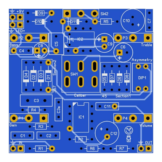
Page 3: Components
Magnum v1.0 Components Name Value Comment Name Value Comment 220p MLCC/Ceramic 1N4001 150n SMF/MKT/Wima 1N4001 C3(a) 22p MLCC/Silver Mica 1N5817 100n SMF/MKT/Wima 1N5817 470n SMF/MKT/Wima DIP1 DIP2 Electrolytic 25V+ JRC4558 SMF/MKT/Wima LT1054 Electrolytic 25V+ A250k Gain Electrolytic 25V+ A25k Bass... -
Page 4: Building Sequence
Magnum v1.0 Building sequence Soldering this board can be very complicated for some people since the solder pads are very close together. Use a magnifying glass to make the job easier. First decide which charge pump you want to use. IC2 can fit a LT1054 or even the cheaper ICL7660S. -
Page 5: Modifications
Magnum v1.0 Modifications Diodes and Op amp You can use other diodes than the mentioned combinations. Try LED’s, MA858/859 (very nice!!), D9E, etc. D1-D4 best fit the bigger glass germanium diodes. D5-D8 best fit the smaller silicon diodes. IC1 can be any dual op amp of your liking. Try the JRC4558, JRC4559, AD712, MC1458, TL072, OPA2134, OP275, etc, etc. -
Page 6: Off Board Wiring
Magnum v1.0 Off board wiring The biggest challenge of this build is to get all the offboard wiring correct and fit it in a box. Take your time measuring and testing before you start fitting everything in the box. P1-P4 are PCB mounted potentiometers (Alpha). The rectangle pad marks pin 1 of a potentiometer. -
Page 7: Troubleshooting
Magnum v1.0 Troubleshooting All PCB’s have been 100% factory e-tested and out of every batch I receive I build an effect to double check, so there should not be a connection problem on the PCB itself. The board is not working (at all), what now? •... -
Page 8: Schematic
Magnum v1.0 Schematic Manufacturer and product names are mentioned solely for circuit identification, and where applicable their trademarks are the property of their respective owners who are in no way associated or affiliated with the author. No cooperation or endorsement...
Need help?
Do you have a question about the Magnum and is the answer not in the manual?
Questions and answers