
Subscribe to Our Youtube Channel
Related Manuals for Ace Reliance 1K

Summary of Contents for Ace Reliance 1K
- Page 1 ACE RELIANCE SENSOR OPERATIONS MANUAL ACE Reliance Sensor Operations Manual V2.4 P a g e...
-
Page 2: Table Of Contents
ACE RELIANCE SENSOR OPERATIONS MANUAL Table of Contents Contents Product Description ............................3 Product Specifications ............................4 Installation tools and materials ........................5 TEC cable preparation ............................9 10 kPSI Sensor Model Installation ......................... 13 1kPSI Sensor Model Installation ........................18 Sensor and cable Integrity testing ........................ -
Page 3: Product Description
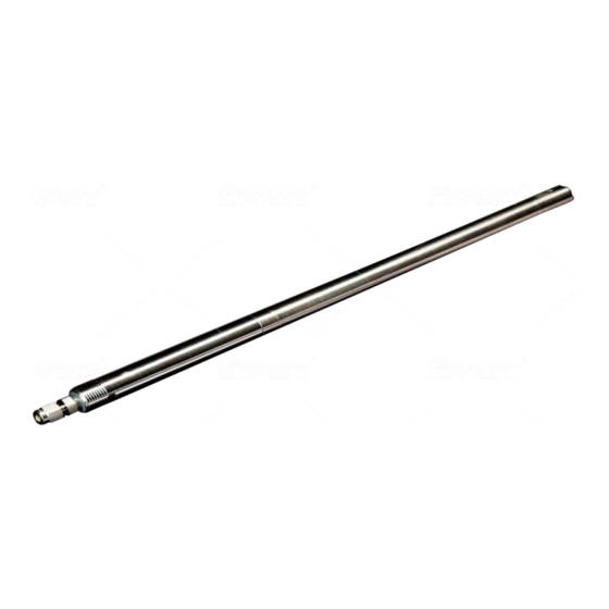
ACE RELIANCE SENSOR OPERATIONS MANUAL 1. Product Description ACE Reliance is a downhole sensor designed to be deployed in non-ESP wells (GasLift, PCP, Rod Lift, Hydraulic Lift, naturally flowing wells …). ACE Reliance sensor consists of two main components - a downhole instrument and a surface read-out unit. The downhole instrument is a completely sealed, welded device. -
Page 4: Product Specifications
SD memory cards. The SRU2i also includes insulation monitoring. The SRU3i adds direct Wi-Fi local connection plus direct connection to Baker Hughes VSD’s. The SRU's operates from nominal 120 VAC50/60Hzline voltage. ACE Optix is a battery powered, solar power capable version. -
Page 5: Installation Tools And Materials
Wrench 3/4” Wrench 11/16” Petroleum jelly (lip balm) Pins (included with the instrument) ACE Downhole strip gauge Dual Seal ¼” (for 10,000 PSI sensors) ACE Downhole strip gauge ¼” (for 1,000 PSI senso model) Crimp tool Vise grips Tube cutter Figure 4. - Page 6 ACE RELIANCE SENSOR OPERATIONS MANUAL Figure 5. 1 ¼” TEC Strip Gauge. This strip gauge is to be used for installing 1 kPSI sensor model WARNING: Ensure an appropriate strip gauge is used for 1,000 PSI and for 10,000 PSI sensor models. Using a wrong strip gauge will lead to incorrectly stripped TEC cable which may cause a sensor failure.
- Page 7 ACE RELIANCE SENSOR OPERATIONS MANUAL Figure 7. Crimp tool (cont.) Figure 8. Wire cutters V2.4 P a g e...
- Page 8 ACE RELIANCE SENSOR OPERATIONS MANUAL Figure 9. Vise grips Figure 10. Tube cutter V2.4 P a g e...
-
Page 9: Tec Cable Preparation
Figure 11. Tube cutter 4.TEC cable preparation 4.1 Use ACE Dual Seal cable strip gauge to measure and mark the cut-off length (fig 12) Figure 12. Measuring and marking the TEC tube cut-off length 4.2 Use tube cutter to make a groove in the tube (fig 13) V2.4... - Page 10 ACE RELIANCE SENSOR OPERATIONS MANUAL Figure 13 4.3 Hold the TEC cable with wise grips on both ends of the groove and wiggle until the end section of the tube breaks loose. Then remove the tube (fig 14 and fig 15).
- Page 11 ACE RELIANCE SENSOR OPERATIONS MANUAL Figure 15 4.4 Use the cable cutter to remove a length of the Teflon insulation as per dimensions of the ACE cable strip gauge (fig 16) Figure 16. TEC cable stripping dimensions as per the ACE Downhole strip gauge 4.5 Insert the end of the TEC cable wire into the pin (fig 15).
- Page 12 ACE RELIANCE SENSOR OPERATIONS MANUAL Figure 4 4.6 Terminate with a pin using the crimp tool (fig 18). If it is assembled but does not match the gauge, then cut off Figure 18. Using the crimp tool to terminate the wire with the pin V2.4...
-
Page 13: Kpsi Sensor Model Installation
ACE RELIANCE SENSOR OPERATIONS MANUAL 4.7 Use the dual seal ¼” strip gauge to doublecheck the dimensions of the terminated end of the TEC cable Figure 19. Dual Seal ¼” strip gauge 5. 10 kPSI Sensor Model Installation 5.1 Unscrew the cover from the head of the sensor... - Page 14 ACE RELIANCE SENSOR OPERATIONS MANUAL Figure 23. Each nut contains a cone and a ferrule 5.2 Slide TEC cable through the nut, ferrule, and the cone. Then slide the TEC cable through the cover. Note the correct orientation of the ferrules and the cones (figure 24) V2.4...
- Page 15 TEC cable, it means the TEC cable was cut incorrectly. The cable needs to be cut and stripped again using the Dual Seal ¼” ACE strip gauge.
- Page 16 ACE RELIANCE SENSOR OPERATIONS MANUAL Figure 26. Correct location of the compressed assembly of the ferrule and the cone 5.5 If you observe that the compressed ferrule the cone is situated on the stainless-steel tubing of the TEC cable it means the cable was stripped correctly.
- Page 17 ACE RELIANCE SENSOR OPERATIONS MANUAL Figure 28. Swagelok gap inspection gauge Apply petroleum jelly (lip balm) on the thread (fig. 26) at the top of the sensor and screw the top cover finger tight, after which tighten it using a ¾” and a 11/16” wrenches (fig. 27) Figure 29 ¾”...
-
Page 18: Kpsi Sensor Model Installation
The installation procedure of the 1kPSI sensor model is similar to the one of the 10kPSI one. One difference is that the 1kPSI model features fewer components (the 1K model does not have the top cover). The other difference is that another ACE TEC strip gauge must be used to measure TEC cut-off distance. Figure 32 Components that are not present in the 1kPSI sensor model are crossed out V2.4... -
Page 19: Sensor And Cable Integrity Testing
1kPSI sensor model and the TEC cable are ready to be connected WARNING: The ACE ¼” Gauge Strip must be used to cut TEC cable for the 1kPSI model. If ACE Dual Seal TEC Strip Gauge is used, this may cause to well fluid leak into the sensor and a failure. Please see the pictures of the two types of ACE TEC strip gauges at the beginning of this manual. -
Page 20: Surface Read-Out Unit Set-Up
8.2 ACE Downhole offers a GPS receiver. If AC mounted in a metallic container it’s possible the internal GPS will not receive a signal, in this case the ACE Optix external GPS receiver may be plugged into the front of the ACE Optix case as shown in the figure 36 below. - Page 21 8.3 Power up the ACE Optix SRU. It will take a couple of minutes for the SRU to initialize. During initialization all LEDs will be blinking. Once initialized without errors, green light only will stay on as shown in the picture 37 below.
- Page 22 SRU 2/SRU3/ ADCM Configuration and Setup Program on acedownhole.com Run ACE SRU configuration program on your PC. You have two options in your Optix SRU to connect to your PC: via RS 232, RS485 serial ports or via USB port. The example below uses USB port for connection. Chise COM3 and V2.4...
- Page 23 ACE RELIANCE SENSOR OPERATIONS MANUAL clock OK. If the PC Serial /IP Comm Status shows “NO RESPONSE” go back to the USB Config menu, select COM4 and press “OK”. The PC Serial/ IP Comm Status should now show “OK” Figure 39 No communication, a wrong serial port is selected in the USB Cfg menu.
-
Page 24: Accessing Downhole Sensor Data Wirelessly From Your Device
9. Accessing downhole sensor data wirelessly from your device 9.1 On your cell phone or a tablet go to “Settings > WiFi” and connect to the ACE OPTIX WiFi network. The last four letters in the WiFI network (2CDO shown below) are the last 4 letters of the ACE Optix device MAC address, so will be different for all ACE Optix devices, allowing them to be identified if several are running close together. - Page 25 9.2. Open a web browser on your device and type 1.2.3.4 in the web address tab. It will take a few seconds for the browser to display Opix SRU status screen. Once ACE Optix SRU has initialized, you will be taken to a set up menu (figure 39).
- Page 26 ACE RELIANCE SENSOR OPERATIONS MANUAL Figure 43 SRU Optix set-up menu V2.4 26 | P a g e...
- Page 27 ACE RELIANCE SENSOR OPERATIONS MANUAL Figure 44 Main sensor status screen on the cell phone 9.3 To download a data log file, click on “Log File Download”. As the message to confirm download shows up, select the day to download (defaults to today) then download (fig. 45) V2.4...
- Page 28 ACE RELIANCE SENSOR OPERATIONS MANUAL Figure 45 Downloading log files 9.4. Once the log file is downloaded you can find it and access it in the top right hand side corner of the web browser fig. 46 V2.4 28 |...
- Page 29 10 seconds. Such design allows for a +10 years’ worth of downhole data to be stored in the ACE Optix SRU.
- Page 30 ACE RELIANCE SENSOR OPERATIONS MANUAL Figure 47. A log file Check for SD and GPS staus. If both SDstaus and GPSStatus lights are green, it means that GPS coordiantes and time are locked and the data logging is initiated ( Fig. 44). If GPS staus light is red, it means that the GPS signal is not locked and the data logging isn’t initiated ( Fig 45).
-
Page 31: Sensor And Cable Integrity Monitoring During Run In Hole
Sensor and Cable Integrity Monitoring During Run in Hole 10.1 ACE Spooler overview The ACE Spooler allows continuous monitoring of an ACE Reliance downhole sensor and the connecting TEC cable in real time during installation. The unit can be mounted inside the rotating cable spool and is electrically connected to the end of the cable inside the spool. - Page 32 ACE RELIANCE SENSOR OPERATIONS MANUAL Any fault conditions from the cable, sensor or interconnect during installation will be apparent within seconds to everyone monitoring the system. The unit is battery powered and will typically operate for 15 hours on the field replaceable, rechargeable batteries.
- Page 33 9.2 ACE Spooler set-up The ACE Spooler set-up is identical to ACE Optix SRU set-up. Data viewing is also the same as for ACE Optix RTU. (please refer to the SRU Optix instructions in this manual). V2.4...
- Page 34 ACE RELIANCE SENSOR OPERATIONS MANUAL Figure 53 Spooler set-up screen 9.3. Spooler log file The start of a typical file will be as follows. The first line will be the GPS coordinates when the Spooler was first turned on. After that each line will have the date, time and the channel readings, in the example below the Spooler.
- Page 35 ACE RELIANCE SENSOR OPERATIONS MANUAL Figure 54 Example Spooler log file 36° 42.73047' N 95° 56.05790' W 05/23/19,09:16:58,72.53,2.20,0.00,0.00,0.00,0.000 05/23/19,09:17:08,72.53,2.20,0.00,0.00,0.00,0.000 05/23/19,09:17:18,72.87,1.84,0.00,0.00,0.00,0.000 05/23/19,09:17:29,72.87,1.84,0.00,0.00,0.00,0.000 05/23/19,09:17:39,72.87,1.33,0.00,0.00,0.00,0.000 05/23/19,09:17:49,72.87,1.03,0.00,0.00,0.00,0.000 05/23/19,09:17:59,72.87,0.98,0.00,0.00,0.00,0.000 05/23/19,09:18:08,73.21,1.37,0.00,0.00,0.00,0.000 05/23/19,09:18:20,73.21,1.37,0.00,0.00,0.00,0.000 05/23/19 09:18:30,73.21,1.04,0.00,0.00,0.00,0.000 Error Conditions: 9.4 Error Conditions The Spooler is able to identify and display three main causes of errors. If the audible beeper is enabled, these will also cause the alarm to sound Fig.
- Page 36 ACE RELIANCE SENSOR OPERATIONS MANUAL Fig. 56 A short circuit again indicates a problem somewhere in the system which may be at the surface or downhole. Turn off the Spooler before trying to locate the problem. Fig. 57 If ‘Cannot decode sensor data’ screen is displayed it indicates that data is being received from the sensor, however the Spooler cannot decode the data.
- Page 37 ACE RELIANCE SENSOR OPERATIONS MANUAL The Spooler is just the opposite, as it draws a very low, limited current (0.1 Amp normally, 0.25 Amp maximum) and its desirable for the Spooler to operate as long as possible without changing the batteries. So although the Spooler will operate with ‘vape’...
- Page 38 ACE RELIANCE SENSOR OPERATIONS MANUAL shorter battery run times. Although users are able to refresh their device screens as quickly as they wish the Spooler defaults to updating each device every 10 seconds (unless prompted by a user request), since faster rates increase power consumption.
Need help?
Do you have a question about the Reliance 1K and is the answer not in the manual?
Questions and answers