
Subscribe to Our Youtube Channel
Related Manuals for Amazone Precea 6000-2


Summary of Contents for Amazone Precea 6000-2
- Page 1 Original operating manual Mounted precision airplanter Precea 6000-2 Precea 6000-2CC Precea 6000-2FCC SmartLearning www .amazone.de...
- Page 2 Please enter the identification data of the implement. The identification data can be found on the rating plate.
-
Page 3: Table Of Contents
TABLE OF CONTENTS TABLE OF CONTENTS Grain singling unit 1 About this operating manual 4.8.1 Layout and function of the grain Diagrams singling unit 1.1.1 Warnings and signal words 4.8.2 Singling disc 1.1.2 Further instructions PreTeC coulter 1.1.3 Instructions 4.9.1 Seeding unit 1.1.4 Lists... - Page 4 TABLE OF CONTENTS Row spacings 6.4.10 Preparing the wheel mark eradicator for operation Mounting category 6.4.11 Preparing the pivoting wheel mark Working speed eradicator for operation Performance characteristics of 6.4.12 Setting up the speed sensor on the the tractor implement 5.10 Noise development data 6.4.13...
- Page 5 TABLE OF CONTENTS Using the track marker 9.1.8 Adjusting the cutting disc distance on the FerTeC Twin coulter 9.1.9 Checking and replacing the inner 8 Parking the machine scraper on the FerTeC Twin coulter 9.1.10 Checking the wheel bolt tightening Emptying the fertiliser hopper torque Emptying the seed hopper...
- Page 6 TABLE OF CONTENTS 9.3.4 Lubricating the roller chain on the mechanical metering drive 9.3.5 Lubricating the roller chain on the central fertiliser metering drive 9.3.6 Lubricating the roller chain on the electric agitator shaft drive Eliminating faults Cleaning the implement 10 Transporting the machine 10.1 Loading the implement with a...
-
Page 7: About This Operating Manual
1 | About this operating manual About this operating manual CMS-T-00000081-D.1 1.1 Diagrams CMS-T-005676-C.1 1.1.1 Warnings and signal words CMS-T-00002415-A.1 Warnings are marked with a vertical bar with a triangular safety symbol and the signal word. The signal words "DANGER", "WARNING" or "CAUTION" describe the severity of the potential danger and have the following meanings: DANGER... -
Page 8: Instructions
1 | About this operating manual Diagrams ENVIRONMENTAL INFORMATION Indicates a risk for environmental damage. NOTE Indicates application tips and instructions for optimal use. 1.1.3 Instructions CMS-T-00000473-B.1 Numbered instructions CMS-T-005217-B.1 Actions that have to be performed in a specific sequence are represented as numbered instructions. The specified sequence of the actions must be observed. -
Page 9: Lists
1 | About this operating manual Diagrams Example: 1. Instruction 1 Alternative instruction 2. Instruction 2 Instructions with only one action CMS-T-005211-C.1 Instructions with only one action are not numbered, but rather shown with a arrow. Example: Instruction Instructions without sequence CMS-T-005214-C.1 Instructions that do not require a specific sequence are shown as a list with arrows. -
Page 10: Other Applicable Documents
Your suggestions for improvement help us Technische Redaktion to create ever more user-friendly operating manuals. Postfach 51 Please send us your suggestions by post, fax or D-49202 Hasbergen email. Fax: +49 (0) 5405 501-234 E-Mail: td@amazone.de MG6967-EN-II | C.1 | 27.09.2021... -
Page 11: Safety And Responsibility
2 | Safety and responsibility Safety and responsibility CMS-T-00007640-A.1 2.1 Basic safety instructions CMS-T-00007641-A.1 2.1.1 Meaning of the operating manual CMS-T-00006180-A.1 Observe the operating manual The operating manual is an important document and a part of the implement. It is intended for the user and contains safety-related information. - Page 12 2 | Safety and responsibility Basic safety instructions the machine must meet the following minimum requirements: The person is physically and mentally capable of controlling the machine. The person can safely perform work with the machine within the scope of this operating manual.
- Page 13 2 | Safety and responsibility Basic safety instructions Farmers can be e.g.: Farmers with higher education or training from a technical college Farmers by experience (e.g. inherited farm, comprehensive practical knowledge) Contractors who work by order of farmers Activity example: Safety training for agricultural helpers 2.1.2.1.4 Agricultural helpers CMS-T-00002313-A.1...
- Page 14 2 | Safety and responsibility Basic safety instructions 2.1.2.3 Danger for children CMS-T-00002308-A.1 Danger for children Children cannot assess dangerous situations and can behave unpredictably. As a result, children are at a higher risk. Keep children away. When you drive out or actuate machine movements, make sure that there are no children in the danger area.
- Page 15 2 | Safety and responsibility Basic safety instructions Observe the technical limit values Non-observance of the technical limits values of the machine can result in accidents and serious personal injury or even death. Moreover, the machine can be damaged. The technical limit values can be found in the Technical Data.
-
Page 16: Knowing And Preventing Dangers
2 | Safety and responsibility Basic safety instructions 2.1.2.4.3 Warning symbols CMS-T-00002317-B.1 Keep warning symbols legible Warning symbols on the machine warn you of risks in danger areas and are an important element of the machine's safety equipment. Missing warning symbols increase the risk of serious and lethal personal injury. - Page 17 2 | Safety and responsibility Basic safety instructions 2.1.3.2 Danger areas CMS-T-00007643-A.1 Dangers areas on the implement The following basic dangers are encountered in the danger areas: The implement and its work tools move during operation. Hydraulically raised implement parts can descend unnoticed and slowly.
-
Page 18: Safe Operation And Handling Of The Machine
2 | Safety and responsibility Basic safety instructions 2.1.4 Safe operation and handling of the machine CMS-T-00002304-H.1 2.1.4.1 Coupling implements CMS-T-00002320-D.1 Coupling the implement on the tractor Incorrectly coupling of the implement to the tractor results in hazards that can cause serious accidents. - Page 19 2 | Safety and responsibility Basic safety instructions 2.1.4.2 Driving safety CMS-T-00002321-D.1 Risk when driving on roads and fields Any mounted or towed implement as well as front or rear ballast weights on the tractor influence the driving behaviour and the steering and braking power of the tractor.
- Page 20 2 | Safety and responsibility Basic safety instructions Preparing the machine for road travel If the machine is not properly prepared for road travel, it can result in serious traffic accidents. Check the lighting and identification for road travel for proper function. Remove coarse dirt from the implement.
-
Page 21: Safe Maintenance And Modification
To ensure that the operating permit remains valid in accordance with national and international regulations, ensure that the specialist workshop only uses conversion parts, spare parts and special equipment approved by AMAZONE. MG6967-EN-II | C.1 | 27.09.2021... - Page 22 2 | Safety and responsibility Basic safety instructions 2.1.5.2 Work on the machine CMS-T-00002323-C.1 Only work on the machine when it is at a standstill If the machine is not standing still, part can move unintentionally or the machine can be set in motion.
- Page 23 2 | Safety and responsibility Basic safety instructions Maintenance work Improper maintenance work, particularly on safety-related components, endangers operational safety. This can result in accidents and serious personal injury or even death. Safety-related components include, for example, hydraulic components, electronic components, frames, springs, trailer coupling, axles and axle suspensions, lines and tanks containing flammable substances.
- Page 24 Before welding on the implement, uncouple the implement from the tractor. 2.1.5.3 Operating materials CMS-T-00002324-C.1 Unsuitable operating materials Operating materials that do not meet AMAZONE requirements can cause implement damage and accidents. Only use operating material that meet the requirements in the Technical Data.
-
Page 25: Safety Routines
CMS-T-00002325-B.1 Special equipment, accessories, and spare parts Special equipment, accessories, and spare parts that do not meet AMAZONE requirements can impede the operational safety of the implement and cause accidents. Only use original parts or parts that meet AMAZONE requirements. - Page 26 2 | Safety and responsibility Safety routines Securing the machine After uncoupling, the implement has to be secured. If the implement and implement parts are not secured, there is a risk of personal injury due to crushing and cutting. Only park the implement on stable and level ground.
- Page 27 2 | Safety and responsibility Safety routines Climbing on and off Negligent behaviour while climbing on and off can cause people to fall off the ladder. People who climb onto the machine without using the intended access steps can slip, fall, and suffer severe injury.
-
Page 28: Intended Use
Further instructions for intended use in special cases can be requested from AMAZONE. Uses other than those specified under the intended use are considered as improper. The manufacturer is not liable for any damage resulting from improper use, solely the operator is responsible. -
Page 29: Product Description
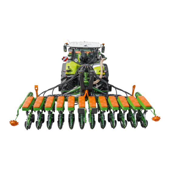
4 | Product description Product description CMS-T-00005533-C.1 4.1 Implement overview CMS-T-00005539-A.1 CMS-I-00004140 Precea 6000-2CC Seeding unit SmartCenter Lighting and identification for road travel Fertiliser hopper Loading board Compressed air fan Running gear, trailing Suction baskets Transport lock 10 Work lights MG6967-EN-II | C.1 | 27.09.2021... - Page 30 4 | Product description Implement overview CMS-I-00004139 Precea 6000-2CC Fertiliser coulter Hose cabinet Lighting and identification for road travel Container for implement documents and other tools Shelf compartment for the collapsible bucket and Track marker scale Wheel mark eradicator Fertiliser filling auger Parking supports MG6967-EN-II | C.1 | 27.09.2021...
- Page 31 4 | Product description Implement overview CMS-I-00003966 Precea 6000-2FCC Container for implement documents and other Parking supports tools 3-point mounting frame Running gear, leading Folding frame Wheel mark eradicator Lighting and identification for road travel Hose cabinet 10 Conveyor line hose connection Frame ballasting MG6967-EN-II | C.1 | 27.09.2021...
-
Page 32: Function Of The Implement
4 | Product description Function of the implement CMS-I-00003967 Precea 6000-2FCC Seeding unit Transport lock Lighting and identification for road travel Compressed air fan Fertiliser coulter Distributor head Track marker Suction baskets 4.2 Function of the implement CMS-T-00005719-B.1 The basic version of the implement consists of a frame with its own running gear, a compressed air fan, and seeding units. -
Page 33: Special Equipment
4 | Product description Special equipment 4.3 Special equipment CMS-T-00005545-B.1 Special equipment is equipment that is not fitted on the implement or is only available in certain markets. The sales documents provide information on the equipment of your implement, or consult your dealer for more detailed information. -
Page 34: Protective Equipment
4 | Product description Protective equipment 4.4 Protective equipment CMS-T-00005540-A.1 4.4.1 Fertiliser metering drive CMS-T-00002012-A.1 4.4.1.1 Guard screen locking mechanism CMS-T-00002016-A.1 To protect against injuries, the guard screens are equipped with locking mechanisms 1 . CMS-I-00001937 4.4.1.2 Electric metering drive CMS-T-00002014-A.1 Drive guard Electric metering drive... -
Page 35: Transport Lock
4 | Product description Warning symbols 4.4.2 Transport lock CMS-T-00005541-A.1 The transport lock 1 prevents the frame parts from unfolding unintentionally. CMS-I-00003932 4.5 Warning symbols CMS-T-00005542-B.1 4.5.1 Position of the warning symbols CMS-T-00005544-B.1 CMS-I-00004141 MG6967-EN-II | C.1 | 27.09.2021... - Page 36 4 | Product description Warning symbols CMS-I-00004142 CMS-I-00003965 MG6967-EN-II | C.1 | 27.09.2021...
-
Page 37: Layout Of The Warning Symbols
4 | Product description Warning symbols CMS-I-00003964 4.5.2 Layout of the warning symbols CMS-T-000141-D.1 Warning symbols indicate danger areas on the machine and warn against residual dangers. In these danger areas, there are permanent or unexpected dangers. A warning symbol consists of two fields: Field 1 shows the following: A pictogram depicting the danger area, CMS-I-00000416... - Page 38 4 | Product description Warning symbols MD082 Danger of falling from treads and platforms when riding on the implement Do not let anybody ride on the implement. Do not let anybody climb onto the driving implement. CMS-I-000081 MD084 Risk of crushing for the whole body from swivelling implement parts! Instruct people to leave the swivel area before the implement parts are swivelled.
- Page 39 4 | Product description Warning symbols MD095 Risk of accident due to non-compliance with the instructions in this operating manual Before you operate the machine, read and understand the operating manual. CMS-I-000138 MD096 Risk of infection for the whole body from hydraulic oil escaping at high pressure Never attempt to plug leaks in hydraulic hose lines using your hand or fingers.
- Page 40 4 | Product description Warning symbols MD 100 Risk of accidents due to improperly attached lifting gear Only attach the lifting gear at the marked positions. CMS-I-000089 MD102 Risk due to unintentional starting and rolling away of the machine Secure the tractor and the machine against unintentional starting and rolling before any intervention in the machine.
- Page 41 4 | Product description Warning symbols MD 108 Severe injuries due to incorrect handling of the hydraulic accumulator when it is under pressure Have the pressurised hydraulic accumulator checked and repaired only by a qualified specialist workshop. CMS-I-00004027 MD 155 Risk of accident and machine damage during transport due to improperly secured machine Only attach the lashing belts at the marked...
-
Page 42: Rating Plate On The Implement
4 | Product description Rating plate on the implement 4.6 Rating plate on the implement CMS-T-00004505-F.1 Implement number Vehicle ID number Product Permissible technical implement weight Model year Year of manufacture CMS-I-00004294 4.7 Compressed air fan CMS-T-00001782-B.1 NOTE When the fan is operated with the tractor PTO shaft, excess grease can emerge from the drive bearings during the initial operating hours. -
Page 43: Singling Disc
4 | Product description Grain singling unit Seed hopper inlet Sliding shutter Air guiding element Opto-sensor Supply area Scraper CMS-I-00002295 The compressed air fan produces the overpressure in the grain singling unit. The grains from the supply area 1 adhere to the holes of the singling disc due to the overpressure. -
Page 44: Pretec Coulter
4 | Product description PreTeC coulter 4.9 PreTeC coulter CMS-T-00005814-B.1 4.9.1 Seeding unit CMS-T-00001771-D.1 The seeding unit is used on ploughed or mulched soils. The seeding unit consists of the grain singling unit, the seed hopper, and the seeding coulter. The seed placement depth and the seeding coulter pressure can be adjusted. -
Page 45: Depth Control Wheels
4 | Product description Fertiliser hopper 4.9.2 Depth control wheels CMS-T-00001975-D.1 The depth control wheels guide the seeding coulter over the soil. Depth control wheels with closed rim 1 have advantages with high amounts of organic residues. The scrapers 2 prevent soil from sticking and ensure that the seeding coulters run smoothly. -
Page 46: Fertec Twin Fertiliser Coulter
4 | Product description FerTeC Twin fertiliser coulter fertiliser metering unit is operated with a mechanical ground wheel drive or an electric drive. The fertiliser hopper has large inspection windows at the front and rear to check the fill level. The rear fertiliser hopper can be safely reached via the loading board. -
Page 47: Filling Auger
4 | Product description Filling auger Cutting discs Fertiliser coulter pressure spring Coulter mount CMS-I-00001963 Cutting discs Coupling rod, spring-suspended Adjustment device CMS-I-00003934 Liquid fertiliser connection Liquid fertiliser outlet CMS-I-00002728 4.12 Filling auger CMS-T-00005567-A.1 The filling auger facilitates the filling procedure for the fertiliser hopper. -
Page 48: Micropellet Spreader
4 | Product description Micropellet spreader Filling auger Filling funnel CMS-I-00001964 Control lever Folding cylinder CMS-I-00003933 4.13 Micropellet spreader CMS-T-00003594-C.1 Depending on the application, the micropellet spreader is used to spread insecticides, slug pellets or micro-fertilisers. Depending on the active substance, the spreading material is applied in the seed furrow, in the closing seed furrow or on the closed seed furrow. - Page 49 4 | Product description Micropellet spreader Micropellet spreader Micropellet metering unit Bottom flap Drive Sliding shutter Micropellet hopper Hopper cover CMS-I-00002590 PreTeC coulter with closer Application in the closing seed furrow, for slug pellet applications. Application in the seed furrow, for insecticide and micro-fertiliser applications.
-
Page 50: Lighting
4 | Product description Lighting 4.14 Lighting CMS-T-00001988-C.1 4.14.1 Lighting and identification for road travel CMS-T-00001768-B.1 Lighting to the rear Warning signs Turn indicators Rear lights and brake lights Red reflectors Yellow reflector Lateral warning signs CMS-I-00001977 NOTE Depending on the national regulations. Lighting to the front Warning signs Side marker lights... -
Page 51: Work Lights
4 | Product description Electronic monitoring 4.14.2 Work lights CMS-T-00001779-B.1 The work lights are used to improve the illumination of the work area. CMS-I-00002218 4.14.3 Hopper interior lighting CMS-T-00001987-B.1 The hopper interior lighting serves for better viewing inside the hopper and makes it easier to check the fill level. -
Page 52: Low Level Sensors
4 | Product description Electronic monitoring 4.15.2 Low level sensors CMS-T-00001979-B.1 4.15.2.1 Seed CMS-T-00001981-B.1 The low level sensor 1 triggers an alarm as soon as the low level sensor is no longer covered with seed. CMS-I-00001986 4.15.2.2 Fertiliser CMS-T-00001983-A.1 The low level sensor 1 triggers an alarm as soon as the low level sensor is no longer covered with fertiliser. -
Page 53: Threaded Cartridge
4 | Product description Threaded cartridge 4.16 Threaded cartridge CMS-T-00001776-C.1 The threaded cartridge contains the following items: Documents Aids CMS-I-00002306 4.17 Calibration kit CMS-T-00007520-A.1 The calibration kit contains the following items: Collapsible bucket Tension scale CMS-I-00005274 4.18 TwinTerminal CMS-T-00004156-A.1 With the TwinTerminal, the following functions can be executed: Calibrate the spread rate Emptying the implement... -
Page 54: Technical Data
The serial number 1 of the Precea 6000-2CC is stamped onto the right of the mounting frame for identification. CMS-I-00004155 The serial number 1 of the Precea 6000-2 or 6000-2FCC is stamped onto the right of the mounting frame for identification. CMS-I-00004153... -
Page 55: Dimensions
5400 – 6800 on the row spacing Centre of gravity distance, depending on the 1200 equipment 5.3 Permissible total weight CMS-T-00005557-A.1 Precea 6000-2 [kg] Precea 6000-2CC [kg] Precea 6000-2FCC [kg] 5300 5300 5300 5.4 Metering unit CMS-T-00002360-D.1 5.4.1 Seed metering unit CMS-T-00002361-D.1... -
Page 56: Fertiliser Metering Unit
5 | Technical data Metering unit Seed hopper [litres] 55/70 5.4.2 Fertiliser metering unit CMS-T-00002362-D.1 NOTE With an electric drive, the spread rate can be adjusted via the forward speed. The maximum spread rate depends on the metered material. The maximum spread rate is based on a working speed of 15 km/h. -
Page 57: Coulters
5 | Technical data Coulters 5.5 Coulters CMS-T-00005568-B.1 5.5.1 PreTeC coulter CMS-T-00005570-B.1 NOTE The maximum placement depth serves as a reference value. The actual value can only be determined during field operation. Coulter Contact force Placement Coulter Load Tare weight [kg] pressure [kg] [kg] depth [cm]... -
Page 58: Mounting Category
5 | Technical data Mounting category Seeding coulter spacing 6000-2 / -2FCC Number of rows Working width [m] [cm] 6.80 6.00 5.40 5.20 6.75 Running gear in front of the seed rows 6.30 5.85 5.40 6.00 5.40 Seeding coulter spacing 6000-2CC Number of rows Working width [m]... -
Page 59: Performance Characteristics Of The Tractor
5 | Technical data Performance characteristics of the tractor 5.9 Performance characteristics of the tractor CMS-T-00005893-A.1 Engine rating Precea 6000-2 Starting at 110 kW / 150 HP Precea 6000-2CC Starting at 110 kW / 180 HP Precea 6000-2FCC Starting at 132 kW / 180 HP... -
Page 60: Gear Oil
5 | Technical data Lubricants Up the slope and down the slope Up the slope Down the slope 5.12 Lubricants CMS-T-00002396-A.1 Manufacturer Lubricant ARAL Aralub HL2 FINA Marson L2 ESSO Beacon 2 SHELL Ratinax A 5.13 Gear oil CMS-T-00003834-A.1 Manufacturer Gear oil WINTERSHALL Wintal UG22 WTL-HM, ex-factory... -
Page 61: Preparing The Machine
6 | Preparing the machine Preparing the machine CMS-T-00005509-B.1 6.1 Calculating the required tractor characteristics CMS-T-00000063-C.1 CMS-I-00000581 Calculated Designation Unit Description values Tractor empty weight Front axle load of the operational tractor without mounted implement or ballast weights Rear axle load of the operational tractor without mounted implement or ballast weights Total weight of front-mounted implement or front ballast Permissible total weight of rear-mounted implement or rear... - Page 62 6 | Preparing the machine Calculating the required tractor characteristics Calculated Designation Unit Description values Distance between the centre of the front axle and the centre of the lower link connection Centre of gravity distance: Distance between the centre of gravity of the front-mounted implement or the front ballast and the centre of the lower link connection Wheelbase...
- Page 63 6 | Preparing the machine Calculating the required tractor characteristics 3. Calculate the actual total weight of the tractor- implement combination. CMS-I-00000515 4. Calculate the actual rear axle load. Htat Vtat Htat Htat CMS-I-00000514 5. Determine the tyre load capacity for two tractor tyres in the manufacturer specifications.
-
Page 64: Adjusting The 3-Point Mounting
6 | Preparing the machine Adjusting the 3-point mounting frame 6.2 Adjusting the 3-point mounting frame CMS-T-00004213-B.1 1. Insert the lower link pins into the mounts. 2. Insert the bolts into the holes. 3. Tighten the bolts with washers and nuts. KAT 3 KAT 3N CMS-I-00003098... -
Page 65: Attaching The Backstop Profiles For
6 | Preparing the machine Coupling the implement 6.3.2 Attaching the backstop profiles for the lower links CMS-T-00001398-A.1 1. Put the backstop profiles 1 on the lower link pins 2 . 2. Secure the backstop profiles with the linch pin CMS-I-00001219 6.3.3 Coupling the universal joint shaft CMS-T-00005462-A.1... - Page 66 6 | Preparing the machine Coupling the implement Type of actuation Function Symbol Latching Permanent oil circulation Oil circulation until action is Momentary executed Free oil flow in the tractor control Floating unit CMS-I-00001699 If there are fewer tractor control units available than are required, multiple implement functions 2 can be assigned to one tractor control unit with the Comfort hydraulic system.
- Page 67 6 | Preparing the machine Coupling the implement Designation Function Tractor control unit Fan hydraulic motor Switching on Single-acting Pressure relief through pressureless return flow WARNING Risk of injury or even death If the hydraulic hose lines are incorrectly connected, the hydraulic functions may be faulty.
-
Page 68: Coupling The Isobus Line
6 | Preparing the machine Coupling the implement 6.3.5 Coupling the ISOBUS line CMS-T-00003611-D.1 1. Insert the plug 1 of the ISOBUS line. 2. Route the ISOBUS line with sufficient freedom of movement and without chafing or pinching points. CMS-I-00004333 6.3.6 Coupling the power supply CMS-T-00001399-D.1 1. -
Page 69: Raising The Jacks
CMS-I-00003939 6. Secure the pin with a spring cotter pin. 7. Repeat the procedure for the second jack 4 . The Precea 6000-2 or 6000-2FCC has sliding jacks. To relieve the jacks, Raise the implement. 9. Pull out the spring cotter pin 1 . -
Page 70: Operation Without Front Hopper
6 | Preparing the machine Preparing the implement for operation 6.3.9 Operation without front hopper CMS-T-00008281-A.1 If the implement should be used without the front hopper, install the terminating resistor 1 on the signal cable 2 for the front hopper. CMS-I-00005657 6.4 Preparing the implement for operation CMS-T-00005513-B.1... -
Page 71: Adjusting The Working Position Sensor
6 | Preparing the machine Preparing the implement for operation REQUIREMENTS The implement is raised The lifting arm is removed WARNING An unexpected hydraulic function is activated Before you actuate the tractor control unit, check the selected hydraulic function of the Comfort hydraulic system. -
Page 72: Filling The Seed Hopper
6 | Preparing the machine Preparing the implement for operation To configure the working position sensor, refer to the ISOBUS software operating manual, "Configuring the working position sensor" see "control computer" operating manual. 6.4.4 Filling the seed hopper CMS-T-00001914-B.1 REQUIREMENTS The implement is coupled to the tractor The tractor and implement are secured The seed and seed hopper are free of foreign... -
Page 73: Filling The Fertiliser Hopper
6 | Preparing the machine Preparing the implement for operation 4. Completely open the seed hopper cover 1 . The cover fastener 2 latches. 5. Fill the seed hopper. CMS-I-00001887 6. Clean the cover seal and sealing surface 2 . 7. - Page 74 6 | Preparing the machine Preparing the implement for operation 3. Secure the tractor and implement. 4. When working at night, switch on the interior lighting of the fertiliser hopper. 5. Climb onto the loading board using the steps. To unfold the ladder, see "Operating the loading board with ladder".
- Page 75 6 | Preparing the machine Preparing the implement for operation 4. Actuate and hold the control lever 1 . 5. Push the filling auger 2 into the desired position. 6. Release the control lever. The filling auger is locked in the desired position. CMS-I-00003949 7.
-
Page 76: Preparing The Micropellet Spreader For Operation
6 | Preparing the machine Preparing the implement for operation 15. Switch off the "beige" tractor control unit. 16. Swivel in the filling chute. 17. Close the cover tarpaulin of the filling funnel. To swivel the filling auger back into the parking position, actuate the "green 1"... - Page 77 6 | Preparing the machine Preparing the implement for operation 3. Open the micropellet hopper cover 1 . 4. Fill the micropellet hopper. CMS-I-00002598 5. Clean the cover seal and sealing surface 1 . 6. Close the micropellet hopper 2 . The lock engages noticeably.
- Page 78 6 | Preparing the machine Preparing the implement for operation 2. Insert the unlocking tool 2 into the metering unit cover 1 . 3. Unlock the metering unit cover on the metering housing 3 . 4. Open the metering unit cover. CMS-I-00002582 5.
- Page 79 6 | Preparing the machine Preparing the implement for operation 8. Take the metering roller 1 out of the roller cage For uniform concentricity, align the direction of rotation of the desired metering roller with the mark 3 . Metering Applicatio Spread Colour...
- Page 80 6 | Preparing the machine Preparing the implement for operation 6.4.6.3 Changing the spread rate for micropellets CMS-T-00003632-C.1 REQUIREMENTS The hopper is at least 1/4 full With the micropellet calibration, you can check whether the desired micropellet quantity is being spread.
- Page 81 6 | Preparing the machine Preparing the implement for operation 8. Put the collapsible bucket in the storage compartment. 9. Put the scale in the storage compartment. 6.4.6.4 Changing the micropellet spread rate CMS-T-00003633-B.1 PreTeC coulter with closer Application in the closing seed furrow, optionally with targeted outlet or diffuser.
-
Page 82: Determining The Setting Parameters
6 | Preparing the machine Preparing the implement for operation To activate the outlet that is suitable for the application, move the switchover flap 1 to the desired position. CMS-I-00002580 6.4.6.5 Adjusting the diffuser angle CMS-T-00003884-B.1 1. Loosen the bolts 1 . 2. - Page 83 6 | Preparing the machine Preparing the implement for operation 120 to Silver 45 ±5 4.0 mm D / E Green 16 mm 16 mm 16 mm 16 mm 265 g grey mbar 120 to 45 ±5 20-16 4.0 mm Purple D / E Green...
-
Page 84: Adjusting The Fan Speed Via The
6 | Preparing the machine Preparing the implement for operation NOTE Operating conditions such as the grain shape, dressing or the addition of talcum affect the correct selection of the singling discs. The selection of the singling discs width must be adapted to the respective operating conditions and can only be determined during field operation. - Page 85 Read the fan pressure on the pressure gauge. NOTE If the desired fan pressure is not reached, a bigger hydraulic motor can help. Please contact your AMAZONE Customer Service. 6.4.9 Preparing the track marker for operation CMS-T-00005514-B.1 6.4.9.1 Calculating the track marker length CMS-T-00001938-C.1...
- Page 86 6 | Preparing the machine Preparing the implement for operation The track marker length L describes the distance from the centre of the implement to the contact area of the track marker disc at the centre of the tractor. NOTE 640 cm working width can only be marked in the tractor track.
- Page 87 6 | Preparing the machine Preparing the implement for operation The track marker length L describes the distance from the centre of the implement to the contact area of the track marker disc in the tractor track. CMS-I-00001216 Unit Designation Calculated values Number of seeding coulters...
- Page 88 6 | Preparing the machine Preparing the implement for operation 6.4.9.2 Unfolding the track markers CMS-T-00005436-B.1 WARNING An unexpected hydraulic function is activated Before you actuate the tractor control unit, check the selected hydraulic function of the Comfort hydraulic system. 1.
- Page 89 6 | Preparing the machine Preparing the implement for operation 6.4.9.4 Adjust the track marker for 5.40 m working width. CMS-T-00005439-B.1 1. Move the track marker mount 4 on the implement section 7 to the desired position. 2. Install the bolts 6 . 3.
-
Page 90: Preparing The Wheel Mark Eradicator For Operation
6 | Preparing the machine Preparing the implement for operation 6.4.9.6 Adjusting the track marker for 6.00 m working width CMS-T-00005441-B.1 1. Move the track marker mount 7 on the implement section 5 to the desired position. 2. Install the bolts 6 . 3. - Page 91 6 | Preparing the machine Preparing the implement for operation 1. Raise the implement. 2. Release the linch pin 2 . 3. Hold the wheel mark eradicator by the recessed grip 1 . 4. Remove the locking pin 3 . The maximum working depth is 150 mm.
- Page 92 6 | Preparing the machine Preparing the implement for operation 6.4.10.3 Changing the wheel mark eradicator coulter CMS-T-00002425-D.1 Different wheel mark eradicator coulters can be installed on the wheel mark eradicator . The choice of the wheel mark eradicator coulter depends on the operating conditions.
-
Page 93: Preparing The Pivoting Wheel Mark Eradicator For Operation
6 | Preparing the machine Preparing the implement for operation 6.4.11 Preparing the pivoting wheel mark eradicator for operation CMS-T-00005518-A.1 6.4.11.1 Adjusting the working depth of the wheel mark eradicators CMS-T-00005519-A.1 NOTE The adjustment of the working depth must be adapted to the respective operating conditions. - Page 94 6 | Preparing the machine Preparing the implement for operation 6.4.11.2 Adjusting the wheel mark eradicator to the track width CMS-T-00005520-A.1 1. loosen the nut 1 . 2. Move the track marker 2 to the desired position. 3. Tighten the nut. CMS-I-00003951 6.4.11.3 Changing the wheel mark eradicator coulter CMS-T-00005521-A.1...
-
Page 95: Setting Up The Speed Sensor On The Implement
6 | Preparing the machine Preparing the implement for operation 2. Remove the bolts. 3. Install the desired wheel mark eradicator coulter on the tool carrier. 4. Install the bolts. 5. Install the nuts and tighten them. 6. After 5 hours of operation, check the bolt connection for tight fit. -
Page 96: Using The Multi-Placement Tester
6 | Preparing the machine Preparing the implement for operation 2. See "Determining the pulses per 100 m" in the control computer operating manual refer to the ISOBUS operating manual, "Setting up the speed sensor on the implement". 6.4.13 Using the multi-placement tester CMS-T-00005293-B.1 6.4.13.1 Determining the grain size CMS-T-00001888-B.1... - Page 97 6 | Preparing the machine Preparing the implement for operation 3. Expose 11 grains in one row. 4. Place the multi-placement tester horizontally on the ground. 5. Measure 10 grain spacings with the ruler 1 . 6. Calculate the average grain spacing. ®...
-
Page 98: Adjusting The Grain Singling Unit
6 | Preparing the machine Preparing the implement for operation 6.4.14 Adjusting the grain singling unit CMS-T-00005516-B.1 6.4.14.1 Changing the singling disc CMS-T-00005572-B.1 1. Secure the tractor and implement. 2. Open the locks 1 . 3. Remove the cover 2 . CMS-I-00001909 4. - Page 99 6 | Preparing the machine Preparing the implement for operation NOTE The filling blocks are only required for folding implement frames. The orange filling block is required for use in rapeseed, beets, or sorghum. Remove the bolt 4 . 7. Install the orange filling block 3 in the mount 8.
- Page 100 6 | Preparing the machine Preparing the implement for operation NOTE The sealing wax dot 1 indicates a factory setting. 16. Check the sealing wax dot. If the sealing wax dot has been broken, contact your specialist workshop. CMS-I-00005636 18. Press the ejector holder 3 together. 19.
- Page 101 6 | Preparing the machine Preparing the implement for operation 25. Align the guide pin 1 . 26. Close the cover 2 . 27. Close the locks. CMS-I-00001913 6.4.14.2 Adjusting the sliding shutter CMS-T-00001901-D.1 NOTE The adjustment of the sliding shutter must be adapted to the respective operating conditions.
- Page 102 6 | Preparing the machine Preparing the implement for operation To determine the position for the sliding shutter, see "Determining the setting parameters". When the fill level rises beyond the edge of the inspection window gradually close the sliding shutter if the fill level falls below the edge of the inspection window, gradually open the sliding shutter...
- Page 103 6 | Preparing the machine Preparing the implement for operation 3. Press the shot channel 3 against the gasket 2 in the funnel 1 . 4. Swivel the shot channel away from the opto- sensor and pull it up. CMS-I-00003815 5.
- Page 104 6 | Preparing the machine Preparing the implement for operation 10. Remove the opto-sensor 1 . CMS-I-00002827 To select the opto-sensor, see "Determining the setting parameters". 12. Install the desired opto-sensor 1 . CMS-I-00002826 13. Move the opto-sensor 1 up. 14.
- Page 105 6 | Preparing the machine Preparing the implement for operation 16. Install the spacer plate 2 . 17. Install the bolts 1 . CMS-I-00003818 The shot channel 3 must be changed to fit the seed. To select the shot channel, see "Determining the setting parameters".
-
Page 106: Changing The Seed Spread Rate
6 | Preparing the machine Preparing the implement for operation If the control terminal detects doubles, increase the setting value on the scraper 1 . If the control terminal detects gaps, reduce the setting value on the scraper 1 . 3. - Page 107 6 | Preparing the machine Preparing the implement for operation Formula symbol Designation Grain spacing [cm] Determine the grain spacing using the equation. ´ 10 000 ´ 10 000 ´ ´ ´ ´ CMS-I-00002047 NOTE For grain spacing ≤ 4 cm, there can be multiples or gaps in the holes of the singling disc.
- Page 108 6 | Preparing the machine Preparing the implement for operation Singling disc with 10 holes Row width Spread rate [G/ha] 0.45 m 0.60 m 0.75 m 0.80 m 0.90 m 10,000 3.9 - 15.0 km/h 3.0 - 15.0 km/h 2.4 - 15.0 km/h 2.2 - 15.0 km/h 2.0 - 15.0 km/h 12,000...
- Page 109 6 | Preparing the machine Preparing the implement for operation Singling disc with 55 holes Row width Spread rate [G/ha] 0.45 m 0.50 m 0.60 m 0.75 m 0.80 m 200,000 15.0 km/h 15.0 km/h 13.6 km/h 10.9 km/h 10.2 km/h 240,000 15.0 km/h 13.6 km/h...
- Page 110 6 | Preparing the machine Preparing the implement for operation Singling disc with 120 holes Row width Spread rate [G/ha] 0.45 m 0.50 m 0.60 m 0.75 m 0.80 m 15.0 km/h 15.0 km/h 15.0 km/h 15.0 km/h 15.0 km/h ≤280,000 320,000 15.0 km/h...
- Page 111 6 | Preparing the machine Preparing the implement for operation 6.4.15.3 Adjusting the mechanically driven grain singling unit CMS-T-00003646-D.1 6.4.15.3.1 Determining the gear ratio with leading wheel drive CMS-T-00003651-B.1 REQUIREMENTS The singling disc is selected The gear wheel in the leading wheel drive is selected To calculate the desired grain spacing from the spread rate,...
- Page 112 6 | Preparing the machine Preparing the implement for operation Depending on the gear wheel in the leading wheel drive and the desired grain spacing, determine the gear ratio for the leading wheel drive from the table. CMS-I-00002869 The determined gear ratio depends on the wheel slip. To determine the pulses per 100 m during field operation, refer to the AmaScan2 operating manual,...
- Page 113 6 | Preparing the machine Preparing the implement for operation ´ 18,2 ´ 300 16 6 , ´ CMS-I-00002684 = Manually calculated grain spacing = Grain spacing determined on the control terminal = Pulses per 100 m, see table above = Determined pulses per 100 m 5.
- Page 114 6 | Preparing the machine Preparing the implement for operation 6.4.15.3.2 Determining the gear ratio with trailing wheel drive CMS-T-00003652-D.1 REQUIREMENTS The singling disc is selected To calculate the desired grain spacing from the spread rate, refer to the AmaScan2 operating manual, "Determining the grain spacing", refer to the AmaCheck operating manual, "Determining the grain spacing".
- Page 115 6 | Preparing the machine Preparing the implement for operation The determined gear ratio depends on the wheel slip. To determine the pulses per 100 m during field operation, refer to the AmaScan2 operating manual, "Running in the pulses", refer to the AmaCheck operating manual, "Running in the pulses".
- Page 116 6 | Preparing the machine Preparing the implement for operation 6.4.15.3.3 Adjusting the grain spacing in the interchangeable wheel gear CMS-T-00003634-C.1 1. Release the lever 2 and swivel it up. The cover 1 opens automatically. CMS-I-00002656 The chain tensioner 3 is relieved. The drive chain 2 is lying loosely on the chain wheels A and B .
- Page 117 6 | Preparing the machine Preparing the implement for operation 13. Remove the cotter pin 3 . 14. Remove the washer 2 . 15. Remove the gear wheel 1 . 16. Take the desired gear wheel from the parking position. 17.
- Page 118 6 | Preparing the machine Preparing the implement for operation 6.4.15.3.4 Replacing the gear wheel in the leading wheel drive CMS-T-00003647-C.1 If the high spread rate is not reached when seeding rapeseed or soya, replace gear wheel Z=15 with gear wheel Z=30.
- Page 119 6 | Preparing the machine Preparing the implement for operation To make the chain lock accessible, turn the drive wheel 1 clockwise. 8. Remove the clamping ring 3 . 9. Remove the gear wheel Z=15. 10. Install the gear wheel Z=30. 11.
-
Page 120: Adjusting The Pretec Coulter
6 | Preparing the machine Preparing the implement for operation 17. Install the cover 1 . 18. Install the bolts and washers 2 . CMS-I-00002645 6.4.15.3.5 Deactivating the mechanically driven grain singling unit CMS-T-00003865-A.1 To deactivate the mechanically driven grain singling unit, remove the shear pin 2 . - Page 121 6 | Preparing the machine Preparing the implement for operation CAUTION The star clearers are subject to wear. This can cause sharp edges. Wear protective gloves. 1. Raise the implement. 2. Secure the tractor and implement. 3. Remove the linch pin 1 . 4.
- Page 122 6 | Preparing the machine Preparing the implement for operation 1. Raise the implement. 2. Secure the tractor and implement. 3. Hold the clod clearer by the handle 1 . 4. Remove the linch pin 2 . 5. Pull out the positioning pin 3 . 6.
- Page 123 6 | Preparing the machine Preparing the implement for operation NOTE The adjustment of the rigid cutting disc must be adapted to the respective operating conditions. The optimum adjustment can only be determined during field operation. 1. Raise the implement. 2.
- Page 124 6 | Preparing the machine Preparing the implement for operation NOTE Position P is only needed for parking the implement. The setting lever 2 can also be engaged in half- steps 1 in the grid. 1. Raise the implement. 2. Secure the tractor and implement. 3.
- Page 125 6 | Preparing the machine Preparing the implement for operation 6.4.16.5 Adjusting the coulter pressure hydraulically CMS-T-00005524-B.1 The coulter pressure is applied with a hydraulic cylinder 1 . CMS-I-00003953 The hydraulic coulter pressure system can be equipped with contact force regulation. The force sensors 1 determine the contact force of the coulters.
- Page 126 6 | Preparing the machine Preparing the implement for operation 6.4.16.6 Adjusting the coulter pressure mechanically CMS-T-00001905-D.1 NOTE The adjustment of the coulter pressure must be adapted to the respective operating conditions. The optimum adjustment can only be determined during field operation. Operating conditions Coulter pressure Increase the coulter...
- Page 127 6 | Preparing the machine Preparing the implement for operation The disc closers are used on ploughed or mulched soils. They cover the seed furrow with fine soil. The disc closer pressure is adjustable. NOTE The adjustment of the disc closer must be adapted to the respective operating conditions.
- Page 128 6 | Preparing the machine Preparing the implement for operation 6.4.16.8 Adjusting the press rollers CMS-T-00001931-D.1 NOTE The adjustment of the press rollers must be adapted to the respective operating conditions. The optimum adjustment can only be determined during field operation. CMS-I-00001953 Number V press rollers...
- Page 129 6 | Preparing the machine Preparing the implement for operation 2. Secure the tractor and implement. 3. Unlock the setting lever 1 . 4. Move the setting lever to the desired position. 5. Lock the setting lever in the grid. 6.
- Page 130 6 | Preparing the machine Preparing the implement for operation 15. Remove the bolt 1 with the press roller. 16. Move the press roller 3 with the setting bushing 2 to the desired position. 17. Install the press roller with bolts. 18.
- Page 131 6 | Preparing the machine Preparing the implement for operation 6.4.16.10 Adjusting the depth control wheel scraper CMS-T-00001936-D.1 IMPORTANT Damage to the wheel due to abrasion by the scraper To check the distance, rotate the wheel NOTE The adjustment of the scraper must be adapted to the respective operating conditions.
- Page 132 6 | Preparing the machine Preparing the implement for operation 2. Put a suitable support 1 under the coulter. To move the locking mechanism to the locking position, slowly lower the implement. The coulter is fixed in the parking position. CMS-I-00002706 4.
- Page 133 6 | Preparing the machine Preparing the implement for operation 6.4.16.12 Adjusting the catch roller scraper CMS-T-00003720-C.1 IMPORTANT Damage to the wheel due to abrasion by the scraper To check the distance, rotate the wheel NOTE The adjustment of the scraper must be adapted to the respective operating conditions.
-
Page 134: Creating Tramlines
6 | Preparing the machine Preparing the implement for operation 1. Raise the implement. 2. Secure the tractor and implement. 3. Remove the nut 1 . 4. Remove the bolt lock 2 . 5. Remove the bolt. 6. Remove the catch roller 3 . To select the catch roller, CMS-I-00002876 see "Determining the setting parameters". -
Page 135: Calibrating The Electrically Driven Fertiliser Metering Unit
6 | Preparing the machine Preparing the implement for operation 6.4.18 Calibrating the electrically driven fertiliser metering unit CMS-T-00003839-D.1 6.4.18.1 Performing the calibration CMS-T-00001945-E.1 REQUIREMENTS The fertiliser hopper is at least full with fertiliser 1. Switch off the fan. 2. Release the lock 2 and swivel it downwards. To take the calibration buckets out of the parking position on implements with hydraulic fan drive,... - Page 136 6 | Preparing the machine Preparing the implement for operation To move the calibration flap lever to the calibration position, press and hold the lock button 1 and push it down. To fill the fertiliser metering unit, Actuate the calibration button 2 for 10 seconds. 8.
- Page 137 6 | Preparing the machine Preparing the implement for operation 6.4.18.2 Determining the maximum fertiliser spread rate CMS-T-00002412-C.1 NOTE The values in the table serve as a reference and require a constant power supply of at least 12 volts. Read the values from the table. CAN / DAP / NPK / phosphate Fertiliser Row spacing [cm]...
-
Page 138: Calibrating The Mechanically Driven Fertiliser Metering
6 | Preparing the machine Preparing the implement for operation Urea Fertiliser Row spacing [cm] quantity 45.0 50.0 60.0 75.0 80.0 [kg / ha] 13.4 12.1 10.1 11.9 10.7 10.6 6.4.19 Calibrating the mechanically driven fertiliser metering CMS-T-00003665-D.1 6.4.19.1 Determining the crank turns for standard working widths CMS-T-00003668-A.1 = Working width in metres = Number of rows... - Page 139 6 | Preparing the machine Preparing the implement for operation 6.4.19.2 Determining the crank turns for special working widths CMS-T-00003669-A.1 = Working width in metres = Number of rows ´ = Row spacing in centimetres ´ 75 4 5 ´ CMS-I-00002685 1.
- Page 140 6 | Preparing the machine Preparing the implement for operation REQUIREMENTS The fertiliser hopper is at least full with fertiliser 1. Switch off the fan. 2. Release the lock 2 and swivel it downwards. To take the calibration buckets out of the parking position on implements with hydraulic fan drive, pull out the interlocked calibration buckets 1 to...
- Page 141 6 | Preparing the machine Preparing the implement for operation 6. Take the operating tool from the parking position 7. Put the operating tool on the gear shaft 2 . CMS-I-00002785 Depending on the working width desired calibration area read the number of crank turns from the table. CMS-I-00002784 MG6967-EN-II | C.1 | 27.09.2021...
- Page 142 6 | Preparing the machine Preparing the implement for operation To move the calibration flap lever to the calibration position, press and hold the lock button 3 and push it down 4 . 10. Release the lock button 1 . 11.
- Page 143 6 | Preparing the machine Preparing the implement for operation The required spread rate is not reached during the first calibration test. Using the values for the first calibration, determine the gearbox position for the desired spread rate, see "Determining the gearbox position with the calculator disc".
-
Page 144: Changing The Application Rate For Liquid Fertiliser
6 | Preparing the machine Preparing the implement for operation NOTE Set the gearbox setting lever between the scale positions 20 and 80. 3. Set the gearbox setting lever to the value read from the disc. The sliding shutter is completely open 1 The sliding shutter is opened to The sliding shutter is closed 3 CMS-I-00002689... - Page 145 6 | Preparing the machine Preparing the implement for operation A = Application rate in litres per hectare ´ = Pure fertiliser application rate in kilograms ´ per hectare = Fertiliser content in percent ´ 55 100 153 5 ϱ = Density in kilograms per litre ´...
-
Page 146: Adjusting The Frame Ballasting
6 | Preparing the machine Preparing the implement for operation 4. Move the valve 1 to the desired position. Since the flow rate depends on the applied material, check the setting by calibrating. Observe the operating manual for the liquid fertiliser tank NOTE The determined values are reference values. -
Page 147: Adjusting The Placement Depth On The Coupled Fertiliser Coulter
6 | Preparing the machine Preparing the implement for operation WARNING An unexpected hydraulic function is activated Before you actuate the tractor control unit, check the selected hydraulic function of the Comfort hydraulic system. NOTE The working range is between 130 and 160 bar. Always rest the frame ballasting on the lower link. -
Page 148: Adjusting The Shifted Tramline
6 | Preparing the machine Preparing the implement for operation 7. Install the linch pin. 8. Make the same adjustment for all fertiliser coulters. 6.4.23 Adjusting the shifted tramline CMS-T-00007955-A.1 With a shifted tramline, tramlines are created without switching off the coulters. The coulter 2 is pushed onto the adjacent coulter 4 with the hydraulic cylinder 1 . -
Page 149: Adjusting The Filling Auger
6 | Preparing the machine Preparing the implement for operation To configure the shifted tramline, see "ISOBUS software operating manual" > "Configuring the tramline control". After configuring the shifted tramline, check whether the desired coulters are shifted. The large spacer elements 1 are 38 mm wide. The small spacer elements 2 are 25.4 mm wide. -
Page 150: Workshop Work
6 | Preparing the machine Preparing the implement for operation CAUTION Risk of tripping due to difficult access to the filling auger For safe access to the filling auger, use a platform ladder. Fertiliser hopper is filled unevenly transverse to the direction of travel. - Page 151 6 | Preparing the machine Preparing the implement for operation REQUIREMENTS Implement lifted in the workshop Secure the lifted implement and components against lowering. Hold the fertiliser coulter in the set position, Loosen the bolts 2 . 2. Move the fertiliser coulter to the desired position. Hold the fertiliser coulter in the desired position, Tighten the bolts.
- Page 152 3 links, and in the lower position, it must be lengthened by 3 links. To adjust the length of the drive chain, see "Replacing the gear wheel in the leading wheel drive". NOTE For more information, please contact your AMAZONE customer service. MG6967-EN-II | C.1 | 27.09.2021...
- Page 153 6 | Preparing the machine Preparing the implement for operation 6.4.25.4 Removing the lifting arm CMS-T-00008179-A.1 IMPORTANT The lifting arm connects the moving frame parts. The lifting arm or the moving frame parts will be damaged when unfolding the implement. Remove the lifting arm.
- Page 154 6 | Preparing the machine Preparing the implement for operation Installing the coulters with a crane is described in the following. To make the coulter tip slightly towards the front for installation, select a longer front load handling device at the front than at the rear.
- Page 155 6 | Preparing the machine Preparing the implement for operation 11. Raise the implement. The depth control wheels 3 are resting on the transport dolly 2 . 12. Loosen the belts 1 from the coulter. 13. Lift the implement further. CMS-I-00005134 14.
- Page 156 6 | Preparing the machine Preparing the implement for operation 6.4.25.5.2 Establishing the energy supply CMS-T-00005490-B.1 1. Disconnect the ISOBUS from the tractor. To activate the coulter, disconnect the coulter wiring harness 1 from the bridge plug 3 . 3. Connect the implement wiring harness 2 to the coulter wiring harness 1 .
- Page 157 6 | Preparing the machine Preparing the implement for operation 4. Loosen the tension belt 2 from the top link 1 and lower link 3 and remove it. CMS-I-00005312 When the hydraulic coulter pressure system is closed again, connect the hydraulic plugs 1 on both implement sections to a vent hose.
- Page 158 6 | Preparing the machine Preparing the implement for operation 2. Install the fertiliser hose 1 on the fertiliser metering unit. 3. Install the clamp 2 . 4. Install the air supply 3 on the air distributor. 5. Install the clamp 4 . CMS-I-00003916 6.4.25.5.5 Establishing the air and fertiliser supply on the distributor head CMS-T-00005489-B.1...
- Page 159 6 | Preparing the machine Preparing the implement for operation 4. Install the air supply 2 on the air distributor. 5. Install the clamp 1 . CMS-I-00003919 6.4.25.6 Removing the PreTeC coulter CMS-T-00005471-B.1 6.4.25.6.1 Removing the coulter CMS-T-00005475-B.1 NOTE Rows with a contact force sensor 1 may not be removed.
- Page 160 6 | Preparing the machine Preparing the implement for operation 4. Remove the bolts 1 . 5. Remove the coulter bracket 2 . CMS-I-00004135 Removing the coulters with a crane is described in the following. To make the coulter tip slightly towards the front for removal, select a longer front load handling device at the front than at the rear.
- Page 161 6 | Preparing the machine Preparing the implement for operation Removing the coulters with the PreTeC transport dolly is described in the following. To set the fertiliser coulters to the topmost position, see "Adjusting the fertiliser placement depth". To set the coulter pressure to the highest value, see "Adjusting the coulter pressure mechanically".
- Page 162 6 | Preparing the machine Preparing the implement for operation 21. Continue lowering the implement. The coulter 1 tips forward. 22. Release the tilted coulter from the frame 2 . CMS-I-00005133 To move the remaining coulters to the desired position, Loosen the bolts 1 .
- Page 163 6 | Preparing the machine Preparing the implement for operation 6.4.25.6.2 Disconnecting the energy supply CMS-T-00005474-B.1 1. Disconnect the ISOBUS from the tractor. To deactivate the coulter, disconnect the coulter wiring harness 1 from the implement wiring harness 2 . 3.
- Page 164 6 | Preparing the machine Preparing the implement for operation To fix the coulter pressure cylinder, lash the top link 1 and the lower link 3 with a tension belt 2 . CMS-I-00005312 ENVIRONMENTAL INFORMATION Danger due to escaping oil Collect any escaping oil.
- Page 165 6 | Preparing the machine Preparing the implement for operation 6.4.25.6.4 Disconnecting the air and fertiliser supply on the rear hopper with central drive CMS-T-00005480-B.1 1. Close the sliding shutter 1 on the fertiliser metering unit. CMS-I-00003915 2. Remove the fertiliser hose from the fertiliser metering unit.
-
Page 166: Preparing The Machine For Road Travel
6 | Preparing the machine Preparing the machine for road travel 2. Remove the clamp 2 . 3. Remove the conveyor hose 1 from the fertiliser coulter 3 . To divert the conveyor air close to the ground, fasten the conveyor hose on the implement with the opening facing down. -
Page 167: Unfolding The Lighting
6 | Preparing the machine Preparing the machine for road travel 6.5.2 Unfolding the lighting CMS-T-00004420-A.1 To be able to unfold the lighting, raise the implement. 2. Unfold both lighting panels 1 . CMS-I-00003215 6.5.3 Folding in the track marker CMS-T-00005530-B.1 WARNING An unexpected hydraulic function is... -
Page 168: Increasing The Mechanical Coulter Pressure
6 | Preparing the machine Preparing the machine for road travel REQUIREMENTS The implement is raised WARNING An unexpected hydraulic function is activated Before you actuate the tractor control unit, check the selected hydraulic function of the Comfort hydraulic system. To fold the implement, actuate the "green 2"... -
Page 169: Calculating The Permissible Payload
6 | Preparing the machine Calculating the permissible payload 6.6 Calculating the permissible payload CMS-T-00002254-C.1 WARNING Risk of accident due to exceeded payload If the payload is exceeded, the implement can be damaged or/and it can result in uncontrolled driving behaviour of the tractor. Carefully determine the payload of the implement. -
Page 170: Using The Machine
7 | Using the machine Using the machine CMS-T-00005576-B.1 7.1 Pre-calibrating the mechanically driven grain singling unit CMS-T-00007525-A.1 To ensure that all grain singling units spread seeds simultaneously, the mechanical drive must be pre- calibrated. To move the coupling finger onto the coupling finger turn the drive wheel of the lifted implement by 360... -
Page 171: Using The Comfort Hydraulic System With Isobus
7 | Using the machine Using the Comfort hydraulic system with ISOBUS NOTE To prevent deviations in the distribution along the row, avoid strong braking and accelerating. The speed of the singling discs is immediately adjusted to normal changes in speed. To check the seed placement depth and grain spacing after the first 30 m, see "Checking the seed placement depth"... -
Page 172: Checking The Placement Depth
7 | Using the machine Checking the placement depth 7.5 Checking the placement depth CMS-T-00004517-B.1 1. Remove the fine soil 1 over the seed 2 . 2. Determine the placement depth 3 . 3. Cover the seed with fine soil again. 4. -
Page 173: Using The Track Marker
7 | Using the machine Using the track marker 7.7 Using the track marker CMS-T-00005898-A.1 If the implement is lifted when "Change" is pre- selected, the job computer actuates the track marker valves. If work is started without actuating the tractor control unit, the position will be faulty. -
Page 174: Parking The Machine
8 | Parking the machine Parking the machine CMS-T-00005562-B.1 8.1 Emptying the fertiliser hopper CMS-T-00001915-C.1 1. Open the spray protection 1 . 2. Open the residual emptying 2 . 3. Collect the residual quantity from the hopper tips on both sides. 4. -
Page 175: Emptying The Seed Hopper Through The Singling Disc
8 | Parking the machine Emptying the seed hopper through the singling disc 2. Hook the chute 1 onto the singling unit. NOTE When the collection bucket is hooked onto the chute, the chute can be loaded with a maximum of 12 kg. - Page 176 8 | Parking the machine Emptying the seed hopper through the singling disc 2. Open the locks 1 . 3. Remove the cover 2 . CMS-I-00001909 4. Hook the chute 1 onto the singling unit. NOTE When the collection bucket is hooked onto the chute, the chute can be loaded with a maximum of 12 kg.
- Page 177 8 | Parking the machine Emptying the seed hopper through the singling disc To collect the residual quantity, remove the singling disc 1 from the drive hub. NOTE When the collection bucket is hooked onto the chute, the chute can be loaded with a maximum of 12 kg.
-
Page 178: Emptying The Fertiliser Metering Unit
8 | Parking the machine Emptying the fertiliser metering unit 8.4 Emptying the fertiliser metering unit CMS-T-00003599-B.1 1. Switch off the fan. 2. Release the lock 2 and swivel it downwards. To take the calibration buckets out of the parking position on implements with hydraulic fan drive, pull out the interlocked calibration buckets 1 to the side. -
Page 179: Emptying The Micropellet Hopper
8 | Parking the machine Emptying the micropellet hopper 9. Empty the calibration bucket. To prevent soiling of the calibration buckets, slide the calibration bucket 1 under the metering unit with the opening facing down. 11. Swivel up the lock 2 and close it. To move the calibration flap lever into working position, press and hold the lock button and push it... - Page 180 8 | Parking the machine Emptying the micropellet hopper 3. Put the collapsible bucket 2 under the activated micropellet outlet 1 . CMS-I-00002621 4. Relieve the bottom flap lever 1 . 5. Slowly open the sliding shutter 1 . The micropellets are collected in the collapsible bucket.
-
Page 181: Relieving The Hole Covering Rollers
8 | Parking the machine Relieving the hole covering rollers 8.6 Relieving the hole covering rollers CMS-T-00002211-A.1 To ensure the concentricity of the hole covering rollers 1 , the hole covering rollers must be relieved when they are not used for longer periods. To do so, the singling discs 2 must be removed from all of the grain singling units. -
Page 182: Parking The Pivoting Wheel Mark Eradicator
8 | Parking the machine Parking the pivoting wheel mark eradicator 4. remove the singling disc 1 from the drive hub. 5. Keep the singling disc in the seed hopper. CMS-I-00001912 6. Close the cover 2 . NOTE Pay attention to the guide pin 1 . 7. -
Page 183: Parking The Wheel Mark Eradicator
8 | Parking the machine Parking the wheel mark eradicator 1. fold the implement. To deactivate the track marker, put the control lever 1 in the locked position. The wheel mark eradicator now remains in the parking position. CMS-I-00003938 8.8 Parking the wheel mark eradicator CMS-T-00001919-B.1 REQUIREMENTS The implement is raised... -
Page 184: Parking The Pretec Coulter
8 | Parking the machine Parking the PreTeC coulter 8.9 Parking the PreTeC coulter CMS-T-00001920-D.1 In the P position, the lowered depth control wheels protect the furrow formers 1 and catch roller 2 . CMS-I-00001999 REQUIREMENTS The implement is raised The fan is switched off 1. -
Page 185: Lowering The Jacks
CMS-I-00004099 6. Secure the pin with a spring cotter pin. 7. Repeat the procedure for the second jack 4 . The Precea 6000-2 or 6000-2FCC has sliding jacks. To relieve the jacks, Raise the implement. 9. Pull out the spring cotter pin 1 . -
Page 186: Disconnecting The Supply Lines From The Hose Package
8 | Parking the machine Disconnecting the supply lines from the hose package 8.11 Disconnecting the supply lines from the hose package CMS-T-00004440-A.1 To disconnect the conveyor hose from the hose package remove the bracket 2 on the connecting piece. ME1212 2. -
Page 187: Disconnecting The Hydraulic
8 | Parking the machine Disconnecting the hydraulic hose lines 8.13 Disconnecting the hydraulic hose lines CMS-T-00000277-D.1 1. Secure the tractor and implement. 2. Put the control lever on the tractor control unit in float position. 3. Disconnect the hydraulic hose lines 1 . 4. -
Page 188: Uncoupling The 3-Point Mounting
8 | Parking the machine Uncoupling the 3-point mounting frame 2. Hang the plugs 1 in the hose cabinet. CMS-I-00001248 8.15 Uncoupling the 3-point mounting frame CMS-T-00001401-C.1 1. Park the implement on a level surface with solid ground. 2. Release the top link 1 . 3. -
Page 189: Conserving The Drive Shaft
8 | Parking the machine Conserving the drive shaft 4. Put the universal joint shaft 1 into the parking position with the rubber strap 2 . CMS-I-00001935 8.17 Conserving the drive shaft CMS-T-00003870-A.1 To ensure that the drive shafts can be smoothly telescoped, seal the shafts with a non-adhesive conservation agent after washing. -
Page 190: Repairing The Machine
9 | Repairing the machine Repairing the machine CMS-T-00005547-B.1 9.1 Maintaining the machine CMS-T-00005899-B.1 9.1.1 Maintenance schedule After initial operation Checking the wheel bolt tightening torque see page 192 Checking the tightening torque for the radar sensor see page 193 bolts Checking the frame connection tightening torque see page 193... - Page 191 9 | Repairing the machine Maintaining the machine Every 12 months Checking the running gear connection tightening see page 194 torque Every 50 operating hours Checking the wheel bolt tightening torque see page 192 Checking the tyre inflation pressure see page 195 Every 10 operating hours / daily Cleaning the cyclone separator see page 197...
-
Page 192: Checking And Replacing The Cutting Discs On The Pretec Coulter
9 | Repairing the machine Maintaining the machine Every 100 operating hours / Every 12 months Cleaning the filling auger see page 198 Cleaning the fertiliser hopper see page 199 Adjusting the micropellet metering unit bottom flap see page 204 9.1.2 Checking and replacing the cutting discs on the PreTeC coulter CMS-T-00002375-D.1 INTERVAL... -
Page 193: Adjusting The Cutting Disc Distance On The Pretec Coulter
9 | Repairing the machine Maintaining the machine 12. Install spacer discs that are not required on the opposite side of the cutting disc bearing with the central bolt. 13. Put on and tighten the central bolt. 14. Install the dust caps. 15. -
Page 194: Adjusting The Cutting Disc Drive On The Pretec Coulter
9 | Repairing the machine Maintaining the machine 7. Install the dust caps. 8. Install the depth control wheel along with the bracket. 9.1.4 Adjusting the cutting disc drive on the PreTeC coulter CMS-T-00002377-E.1 INTERVAL Every 50 operating hours Every 3 months 1. -
Page 195: Checking And Replacing The Closer Discs On The Pretec Coulter
9 | Repairing the machine Maintaining the machine 9.1.5 Checking and replacing the closer discs on the PreTeC coulter CMS-T-00008304-A.1 INTERVAL Every 100 operating hours Every 3 months 1. Determine the diameter of the closer discs. If the diameter of the closer discs is smaller than 180 mm, replace the closer discs in pairs. -
Page 196: Checking And Replacing The Cutting Disc On The Fertec Twin Coulter
9 | Repairing the machine Maintaining the machine 9.1.7 Checking and replacing the cutting disc on the FerTeC Twin coulter CMS-T-00002379-D.1 INTERVAL Every 100 operating hours Every 3 months 1. Determine the cutting disc diameter. 32 Nm If the diameter of the cutting disc is smaller than 340 mm, replace the cutting disc. -
Page 197: Adjusting The Cutting Disc Distance On The Fertec Twin Coulter
9 | Repairing the machine Maintaining the machine 9.1.8 Adjusting the cutting disc distance on the FerTeC Twin coulter CMS-T-00002380-D.1 INTERVAL Every 100 operating hours as required With increasing wear of the cutting discs, the distance between the cutting discs also increases. 1. -
Page 198: Checking The Wheel Bolt Tightening Torque
9 | Repairing the machine Maintaining the machine REQUIREMENTS The tractor and implement are secured 1. Remove the dust caps 1 . 2. Unscrew and remove the central bolts 2 . 220 Nm NOTE The central bolts have different threads: The right central bolt has right-hand thread The left central bolt has left-hand thread CMS-I-00002020... -
Page 199: Checking The Tightening Torque For The Radar Sensor Bolts
9 | Repairing the machine Maintaining the machine 9.1.11 Checking the tightening torque for the radar sensor bolts CMS-T-00002383-D.1 INTERVAL After initial operation Every 12 months NOTE When the tightening torque is too high, the spring- suspended sensor mount is warped and the radar sensor does not work properly. -
Page 200: Checking The Coulter Connection Tightening Torque
9 | Repairing the machine Maintaining the machine 9.1.13 Checking the coulter connection tightening torque CMS-T-00002385-C.1 INTERVAL After initial operation Every 12 months On telescopic coulters Tighten the bolts to 160 Nm -180° On non-telescopic coulters Tighten the bolts to 200 Nm. NOTE The tightening torques must be checked when the coulters are unloaded. -
Page 201: Checking The Tyre Inflation Pressure
9 | Repairing the machine Maintaining the machine 9.1.15 Checking the tyre inflation pressure CMS-T-00002387-A.1 INTERVAL After initial operation Every 50 operating hours Tyres Tyre inflation pressure Tyres 6.5/80x15-AS 2.4 bar Tyres 26x12-12 AS 2.4 bar Check the tyre inflation pressure. 9.1.16 Checking the top link pin and lower link pin CMS-T-00002330-E.1 INTERVAL... -
Page 202: Cleaning The Fan Rotor
9 | Repairing the machine Maintaining the machine Hydraulic hose lines must not be more than 6 years old. 3. Check the manufacturing date 1 . CMS-I-00000532 4. Have any worn, damaged or aged hydraulic hose lines immediately replaced at a specialist workshop. -
Page 203: Cleaning The Cyclone Separator
9 | Repairing the machine Maintaining the machine 9.1.19 Cleaning the cyclone separator CMS-T-00003779-B.1 INTERVAL Every 10 operating hours daily For the cyclone separator to work, the separator opening 3 must be free of impurities. 1. Check the separator opening 3 . If the separator opening in clogged, open the clips 2 . -
Page 204: Cleaning The Filling Auger
9 | Repairing the machine Maintaining the machine 9.1.21 Cleaning the filling auger CMS-T-00002391-A.1 INTERVAL Every 100 operating hours Every 12 months REQUIREMENTS The implement is coupled to the tractor The fan is switched off The filling auger is switched off The tractor and implement are secured 1. -
Page 205: Cleaning The Fertiliser Hopper
9 | Repairing the machine Maintaining the machine 9.1.22 Cleaning the fertiliser hopper CMS-T-00002392-B.1 INTERVAL Every 100 operating hours Every 12 months REQUIREMENTS The implement is coupled to the tractor The tractor and implement are secured 1. Switch off the filling auger 2. - Page 206 9 | Repairing the machine Maintaining the machine 12. Release the lock 1 and swivel it downwards. To move the calibration buckets into calibration position on an implement with hydraulic fan drive, pull out the interlocked calibration buckets 2 by 10 cm to the side.
-
Page 207: Cleaning The Fertiliser Metering Unit
9 | Repairing the machine Maintaining the machine 24. Close the fertiliser hopper tarpaulin. 25. Secure the fertiliser hopper tarpaulin with rubber straps. 9.1.23 Cleaning the fertiliser metering unit CMS-T-00002473-C.1 INTERVAL Every 10 operating hours daily REQUIREMENTS The implement is coupled to the tractor The fan is switched off The filling auger is switched off To close the fertiliser hopper on the metering... -
Page 208: Cleaning The Micropellet Metering Unit
9 | Repairing the machine Maintaining the machine 9.1.24 Cleaning the micropellet metering unit CMS-T-00003601-B.1 INTERVAL Every 10 operating hours daily 1. Move the switchover flap 1 to position A . CMS-I-00002580 2. Close the the sliding shutter 2 on the micropellet hopper. - Page 209 9 | Repairing the machine Maintaining the machine 7. Turn the drive unit 1 counterclockwise. 8. Pull the drive unit out of the metering housing. CMS-I-00002585 9. Take the roller cage 1 along with the metering roller out of the metering housing. CMS-I-00002584 10.
-
Page 210: Adjusting The Micropellet Metering Unit Bottom Flap
9 | Repairing the machine Maintaining the machine 14. Insert the roller cage 1 along with the metering roller into the metering housing. CMS-I-00002584 15. Insert the drive unit 1 into the metering roller. 16. Rotate the drive unit clockwise. 17. -
Page 211: Clean The Singling Unit
9 | Repairing the machine Maintaining the machine 9.1.26 Clean the singling unit CMS-T-00003718-A.1 INTERVAL Every 10 operating hours daily Keep the singling unit head free of dust, deposits, and foreign objects. NOTE Under very dusty operating conditions, the inspection interval must be shortened. 1. -
Page 212: Cleaning The Opto-Sensor
9 | Repairing the machine Maintaining the machine 8. Turn the lock beyond the notch 2 . The points 1 and 3 are no longer aligned. CMS-I-00001911 9. Close the cover 2 . NOTE Pay attention to the guide pin 1 . 10. - Page 213 9 | Repairing the machine Maintaining the machine 4. Release the lock 1 until the points 2 are aligned. CMS-I-00001910 5. remove the singling disc 1 from the drive hub. CMS-I-00001912 To clean the opto-sensor, use tap water with dishwashing detergent. Loosen contamination with the supplied brush for 1 minute 7.
- Page 214 9 | Repairing the machine Maintaining the machine 11. Press the shot channel 3 against the gasket 2 in the funnel 1 . 12. Swivel the shot channel away from the opto- sensor and pull it up. CMS-I-00003815 13. Remove the bolts 1 . 14.
- Page 215 9 | Repairing the machine Maintaining the machine IMPORTANT Damage to the opto-sensor due to cleaning To avoid damage to the sensors, only clean the opto-sensor with the supplied brush. To avoid damage to the electronics, never immerse the plug connector in liquids when it is unplugged.
- Page 216 9 | Repairing the machine Maintaining the machine 23. Move the opto-sensor 1 up. 24. Put on the gasket 2 . 25. Establish the plug connection 3 . CMS-I-00003817 26. Install the spacer plate 2 . 27. Install the bolts 1 . CMS-I-00003818 28.
-
Page 217: Checking The Wheel Mark Eradicator Coulter
9 | Repairing the machine Maintaining the machine 30. Install the shot channel with the spring cotter pin 31. Establish the ISOBUS connection to the tractor. 32. Restart the implement. CMS-I-00003814 9.1.28 Checking the wheel mark eradicator coulter CMS-T-00002497-D.1 INTERVAL Every 50 operating hours Every 3 months IMPORTANT... -
Page 218: Cleaning The Distributor Head
9 | Repairing the machine Maintaining the machine 9.1.29 Cleaning the distributor head CMS-T-00005594-B.1 INTERVAL at the end of the season 1. Use a suitable aid to safely reach the distributor head. 2. Loosen the knurled screws 1 . 3. Remove the cover 2 . CMS-I-00003957 4. - Page 219 9 | Repairing the machine Maintaining the machine To empty the hydraulic accumulator perform maintenance work, open the ventilation valve 2 . CMS-I-00004130 MG6967-EN-II | C.1 | 27.09.2021...
-
Page 220: Lubricating The Machine
9 | Repairing the machine Lubricating the machine 9.2 Lubricating the machine CMS-T-00005548-B.1 IMPORTANT Implement damage due to improper lubrication Grease the implement at the marked lubrication points according to the lubrication schedule. To ensure that dirt is not pressed into the lubrication points, thoroughly clean the grease nipples and the grease gun. -
Page 221: Overview Of Lubrication Points
9 | Repairing the machine Lubricating the machine 9.2.1 Overview of lubrication points CMS-T-00005549-B.1 CMS-I-00004115 Every 50 operating hours CMS-I-00004114 CMS-I-00004111 MG6967-EN-II | C.1 | 27.09.2021... - Page 222 9 | Repairing the machine Lubricating the machine CMS-I-00004113 CMS-I-00004112 CMS-I-00004110 MG6967-EN-II | C.1 | 27.09.2021...
-
Page 223: Lubricating The Roller Chains
9 | Repairing the machine Lubricating the roller chains 9.3 Lubricating the roller chains CMS-T-00007653-A.1 IMPORTANT Implement damage due to improper lubrication Grease the implement at the marked lubrication points according to the lubrication schedule. Before lubrication, clean the chain with only a penetrating oil and a brush. - Page 224 9 | Repairing the machine Lubricating the roller chains 4. Lubricate the roller chain 1 from the inside going out. 5. Check chain tensioner 2 for ease of movement. CMS-I-00003884 6. Install the cover. 7. Install the bolts and washers. CMS-I-00002645 MG6967-EN-II | C.1 | 27.09.2021...
-
Page 225: Lubricating The Roller Chain In The Interchangeable Wheel Gear
9 | Repairing the machine Lubricating the roller chains 9.3.2 Lubricating the roller chain in the interchangeable wheel gear CMS-T-00005449-B.1 INTERVAL After the first 10 operating hours Every 50 operating hours at the end of the season 1. Release the lever 2 and swivel it up. The cover 1 opens automatically. -
Page 226: Lubricating The Roller Chain In The Trailing Wheel Drive
9 | Repairing the machine Lubricating the roller chains 6. Close the cover 1 against the spring pressure. To lock the cover, Continue actuating the lever 3 . The cover will be locked on the chain tensioner CMS-I-00002647 9.3.3 Lubricating the roller chain in the trailing wheel drive CMS-T-00005450-B.1 INTERVAL After the first 10 operating hours... - Page 227 9 | Repairing the machine Lubricating the roller chains 3. Lubricate the roller chain 2 from the inside going out. 4. Check chain tensioner 1 for ease of movement. CMS-I-00003887 5. Install the cover. 6. Install the bolts and washers. CMS-I-00002720 MG6967-EN-II | C.1 | 27.09.2021...
-
Page 228: Lubricating The Roller Chain On The Mechanical Metering Drive
9 | Repairing the machine Lubricating the roller chains 9.3.4 Lubricating the roller chain on the mechanical metering drive CMS-T-00005877-B.1 INTERVAL After the first 10 operating hours Every 50 operating hours at the end of the season 1. Remove the bolts 1 . 2. -
Page 229: Lubricating The Roller Chain On The Central Fertiliser Metering Drive
9 | Repairing the machine Lubricating the roller chains 9.3.5 Lubricating the roller chain on the central fertiliser metering drive CMS-T-00005451-B.1 INTERVAL After the first 10 operating hours Every 50 operating hours at the end of the season 1. Remove the bolts 1 . 2. -
Page 230: Lubricating The Roller Chain On The Electric Agitator Shaft Drive
9 | Repairing the machine Lubricating the roller chains 9.3.6 Lubricating the roller chain on the electric agitator shaft drive CMS-T-00007652-A.1 INTERVAL After the first 10 operating hours Every 50 operating hours at the end of the season 1. Remove the bolts 1 . 2. -
Page 231: Eliminating Faults
9 | Repairing the machine Eliminating faults 9.4 Eliminating faults CMS-T-00005550-B.1 Errors Cause Solution Track marker collision protection The track marker has encountered see page 227 has been triggered. a solid obstacle. The shear bolt is torn and the track marker folded to the rear. - Page 232 9 | Repairing the machine Eliminating faults Errors Cause Solution Speed fluctuations on the hydraulic Speed fluctuations occur on the Contact your specialist drive. hydraulic drive. workshop. The fill level in the singling unit The brushes of the filling block are see page 231 housing is too high.
- Page 233 9 | Repairing the machine Eliminating faults 9.4.1 Track marker collision protection has been triggered. CMS-T-00005551-B.1 The track marker has encountered a solid obstacle. The shear bolt is torn and the track marker folded to the rear. NOTE Only use original bolts as a replacement. Refer to the online spare parts list.
- Page 234 9 | Repairing the machine Eliminating faults 9.4.3 The seed is not caught and jumps out of the furrow. CMS-T-00002347-C.1 The seed collides against the catch roller or against the seed furrow. NOTE If the seed collides against the catch roller 1 or the seed furrow 2 , it is not reliably caught.
- Page 235 9 | Repairing the machine Eliminating faults 9.4.5 Press rollers get blocked. CMS-T-00002373-B.1 Clods or stones get jammed between the press rollers. NOTE Offset installation is not possible in conjunction with disc closers. 1. Unscrew the nut 1 and remove it. 2.
- Page 236 9 | Repairing the machine Eliminating faults Organic residues get stuck on the open rims. Clean the depth control wheels If the predominant operating conditions do not allow for continuous operation of the implement, replace the depth control wheels with open rim with depth control wheels with closed rim.
- Page 237 9 | Repairing the machine Eliminating faults Fuse for the mechanical drive is defective. 1. Remove the defective shear pin 2 . 2. Remove the defective shear pin from the drive shaft 3 . 3. Clean the singling unit. 4. Check the singling disc for ease of movement. 5.
-
Page 238: Cleaning The Implement
9 | Repairing the machine Cleaning the implement 9.4.9 The fertiliser coupling is leaky. CMS-T-00008171-A.1 The funnels for the fertiliser coupling are misadjusted. As soon as the folding frame has been moved into working position, the funnels 3 move onto the conical mounts 1 . -
Page 239: Transporting The Machine
10 | Transporting the machine Transporting the machine CMS-T-00005552-A.1 10.1 Loading the implement with a crane CMS-T-00005555-A.1 CMS-I-00004146 CMS-I-00004150 MG6967-EN-II | C.1 | 27.09.2021... - Page 240 10 | Transporting the machine Loading the implement with a crane CMS-I-00004148 The implement has lashing points for slings. WARNING Risk of accidents due to improperly attached lifting gear If the lifting gear is not attached at suitable positions, the machine or components can be damaged during loading and endanger safety.
-
Page 241: Moving The Implement With A Transport Vehicle
10 | Transporting the machine Moving the implement with a transport vehicle REQUIREMENTS The implement is unfolded 1. Only attach the lifting gear at the marked positions. 2. Hang the slings on the crane with a crossbeam. 3. Load the machine with a crane. CMS-I-000089 10.2 Moving the implement with a transport vehicle CMS-T-00005554-A.1... - Page 242 10 | Transporting the machine Moving the implement with a transport vehicle CMS-I-00004150 REQUIREMENTS Implement is folded 1. Only attach the lifting gear at the marked positions. 2. Secure the implement in accordance with the regulations to the transport vehicle. CMS-I-00000450 MG6967-EN-II | C.1 | 27.09.2021...
-
Page 243: Appendix
11 | Appendix Appendix CMS-T-00001755-B.1 11.1 Bolt tightening torques CMS-T-00000373-B.1 CMS-I-000260 NOTE Unless specified otherwise, the bolt tightening torques listed in the table apply. 10.9 12.9 M8x1 16(17) M10x1 18(19) M12x1.5 M 14x1.5 M16x1.5 M18x1.5 M20x1.5 MG6967-EN-II | C.1 | 27.09.2021... -
Page 244: Other Applicable Documents
11 | Appendix Other applicable documents 10.9 12.9 M22x1.5 1050 1000 1200 M24x2 1100 1300 1050 1500 1800 M27x2 1150 1600 1950 1450 2000 2400 M30x2 1600 2250 2700 CMS-I-00000065 20.4 40.7 70.5 11.2 Other applicable documents CMS-T-00001756-B.1 Tractor operating manual ISOBUS software operating manual Control terminal operating manual MG6967-EN-II | C.1 | 27.09.2021... -
Page 245: Directories
12 | Directories Directories 12.1 Glossary CMS-T-00000513-B.1 Machine Mounted implements are accessory parts of the tractor. However, mounted implements are always referred to as the implement in this operating manual. Operating materials Operating materials serve to ensure operational readiness. Operating materials include e.g. cleaning agents and lubricants such as lubricating oil, greases or cleaners. -
Page 246: Index
12 | Directories Index 12.2 Index Determining the gear ratio with leading wheel drive Determining the gear ratio with trailing wheel 3-point mounting frame drive adjusting Electrically driven fertiliser metering coupling Electrically driven grain singling unit uncoupling Manually calculating the grain spacing Mechanically driven fertiliser metering Replacing the gear wheel in the leading Address... - Page 247 12 | Directories Index Coupling supply lines to the hose package Fan speed Coupling the implement adjusting via the hydraulic system Raising the jacks FerTeC Twin coulter Coupling the supply lines to the hose package Adjusting the cutting disc distance Coupling the universal joint shaft Checking and replacing the cutting discs Checking and replacing the inner scraper...
- Page 248 12 | Directories Index Loading the implement with a crane Loads Implement, coupling calculation Coupling the ISOBUS line Lower link pin Coupling the power supply checking Coupling the universal joint shaft Lubricants Implement lowering Lubricating the machine Implement overview Implement cleaning preparing for operation Maintaining the machine...
- Page 249 12 | Directories Index Uncoupling the universal joint shaft Preparing the wheel mark eradicator for operation Adjusting the working depth Parking the machine Changing the wheel mark eradicator coulter Disconnecting the supply lines from the hose package Press rollers Emptying the fertiliser metering unit adjustment Lowering the jacks blocking...
- Page 250 12 | Directories Index Roller chains Mounting category Lubricating the mechanical metering drive Noise development data Lubricating the trailing wheel drive Performance characteristics of the tractor Permissible total weight Running gear height PreTeC coulter adjusting Row spacings Seed metering unit Serial number Working speed Seed equipment...
- Page 251 12 | Directories Index Turning on the headlands Using the multi-placement tester Checking the grain spacing Checking the seed placement depth Determining the grain size Warning symbols Description of the warning symbols Layout Position of the warning symbols Wheel mark eradicator Adjusting the track width Adjust the working depth Changing the coulter...
- Page 254 AMAZONEN-WERKE H. DREYER SE & Co. KG Postfach 51 49202 Hasbergen-Gaste Germany +49 (0) 5405 501-0 amazone@amazone.de www.amazone.de MG6967-EN-II | C.1 | 27.09.2021...
Need help?
Do you have a question about the Precea 6000-2 and is the answer not in the manual?
Questions and answers