Baker Hughes Masoneilan SVi 1000 Quick Start Manual
Hide thumbs
Also See for Masoneilan SVi 1000:
- Instruction manual (128 pages) ,
- Instruction manual (16 pages)

Related Manuals for Baker Hughes Masoneilan SVi 1000


Summary of Contents for Baker Hughes Masoneilan SVi 1000
- Page 1 Masoneilan ™ 1000 ™ Positioner Quick Start Guide (Rev. M) Baker Hughes Data Classification: Public...
-
Page 2: About This Guide
All information contained herein is believed to be accurate at the time of publication and is subject to change without notice. Copyright 2021 by Baker Hughes Company. All rights reserved. PN 0720008664-779-0000 REV M. © 2021 Baker Hughes Company. All rights reserved. -
Page 3: Table Of Contents
Step 3: Wiring the SVi1000 ................31 Wiring Guidelines .................. 32 Wiring an SVi1000 Unit ................. 33 Troubleshooting Connections ..............35 Position Retransmit Units .................... 35 © 2021 Baker Hughes Company. All rights reserved. Masoneilan SVi1000 Positioner Quick Start Guide | 3... - Page 4 Wiring Option #2 ......................56 Configuration Considerations ..................56 Optional Retransmit Output ..............57 Introduction ....................57 Appendix C. Determining an SVI Positioner Compliance Voltage in a Control System ................58 Compliance Test Set-Up ....................58 © 2021 Baker Hughes Company. All rights reserved.
- Page 5 Appendix D. Specifications, Spare Parts & References ....60 Physical and Operational Specifications ............60 Spare Parts................... 64 Spare part kits available include: ................64 Hazardous Location Installation ............65 © 2021 Baker Hughes Company. All rights reserved. Masoneilan SVi1000 Positioner Quick Start Guide | 5...
- Page 6 Updated Load Limits section. Skipped K. Updated software installation section. Added support contact information. Updated L/06-2019 graphics in DO switches section. Update ES-761 to Rev H. ES-761 Safe Use Instructions removed. M/08-2021 Rebranded to Baker Hughes. © 2021 Baker Hughes Company. All rights reserved.
- Page 7 © 2021 Baker Hughes Company. All rights reserved. Masoneilan SVi1000 Positioner Quick Start Guide | 7...
-
Page 8: Safety Information
CAUTION Indicates a potentially hazardous situation, which if not avoided could result in instrument or property damage, or data loss. NOTE Indicates important facts and conditions. © 2021 Baker Hughes Company. All rights reserved. -
Page 9: Svi1000 Product Safety
• Installed, put into service and maintained by qualified and competent professionals who have undergone suitable training for instrumentation used in such areas. © 2021 Baker Hughes Company. All rights reserved. Masoneilan SVi1000 Positioner Quick Start Guide | 9... -
Page 10: Masoneilan Help Contacts
Changes to specifications, structure, and components used may not lead to the revision of this manual unless such changes affect the function and performance of the product. Masoneilan Help Contacts • Email: svisupport@bakerhughes.com • Phone: 888-SVI-LINE (888-784-5463) 10 | © 2021 Baker Hughes Company. All rights reserved. -
Page 11: Installation And Set Up
Upper Stop Button and LED 2 Ground Auto Tune Button and LED 3 Configuration Selection Switch 4-20 mA Input Signal Open Stop Adjustment Screw © 2021 Baker Hughes Company. All rights reserved. Masoneilan SVi1000 Positioner Quick Start Guide | 11... -
Page 12: Solid State Switchs Sw #1 & Sw #2
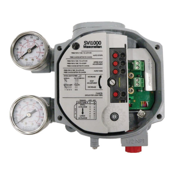
Figure 3 shows the optional position retransmit interface board and optional gauges. 4-20 mA Output Signal (Optional) 4-20 mA Input Signal Gauges (Optional) Ground Figure 3 - Optional Position Retransmit 12 | © 2021 Baker Hughes Company. All rights reserved. - Page 13 This function is only active when the Configuration Selector Switch is set to AutoTune. See Auto Tune on page 44 for this procedure. © 2021 Baker Hughes Company. All rights reserved. Masoneilan SVi1000 Positioner Quick Start Guide | 13...
-
Page 14: Modes
Perform a Manual Find Stops o Set Open Stop Adjustment o Set Valve Position o Command valve to full open or closed 14 | © 2021 Baker Hughes Company. All rights reserved. - Page 15 (see LED Light Functions on page 16). Examples of Commission Processes are Auto Find Stops and AutoTune. Once a task completes the unit returns to Normal mode. © 2021 Baker Hughes Company. All rights reserved. Masoneilan SVi1000 Positioner Quick Start Guide | 15...
-
Page 16: Led Light Functions
In Table 1 dots represent an LED being active and dashes represent the LEDs off. The pattern shown recurs as long as that condition exists. Figure 5 - Example LED Pattern 16 | © 2021 Baker Hughes Company. All rights reserved. - Page 17 If a setting is out of range the associated Green LED flashes at twice Setting out of range the rate as normal until an acceptable range is applied. © 2021 Baker Hughes Company. All rights reserved. Masoneilan SVi1000 Positioner Quick Start Guide | 17...
-
Page 18: Major Components
Major Components Figure 6 shows the unit’s major components for reference. Pneumatic Relay Terminal Board Electronics Module Figure 6 - SVi1000 Major Components 18 | © 2021 Baker Hughes Company. All rights reserved. - Page 19 © 2021 Baker Hughes Company. All rights reserved. Masoneilan SVi1000 Positioner Quick Start Guide | 19...
-
Page 20: Mounting And Wiring
® a HART filter. Loss of control or a process upset may ® occur if the controller output circuit is not compatible with a HART signal. ® 20 | © 2021 Baker Hughes Company. All rights reserved. -
Page 21: Step 1: Mounting The Svi1000
Bleed air from actuator and check that valve is in its unenergized position. For the procedure to install rotary and reciprocating mounting kits on valves, refer to the instructions contained in the valve’s mounting box kit. © 2021 Baker Hughes Company. All rights reserved. Masoneilan SVi1000 Positioner Quick Start Guide | 21... -
Page 22: Mounting The Svi1000 On Rotary Valves
Figure 8 shows a side view of a Camflex actuator, the SVi1000, and a mounting bracket. Magnet SVi1000 Rotary Actuator Mounting Bracket Figure 8 Camflex with Mounting Bracket (Side View) 22 | © 2021 Baker Hughes Company. All rights reserved. - Page 23 Off Shaft bracket to the left when facing the x 0.62” Long actuator if possible. Figure 9 - Rotary Mounting Bracket to Valve Actuator © 2021 Baker Hughes Company. All rights reserved. Masoneilan SVi1000 Positioner Quick Start Guide | 23...
-
Page 24: Internal Valve Pressure
5. Ensure no interference exists with the position sensor protrusion. 6. Ensure that the V-Seal makes contact with the skirt around the alignment ring on the SVi1000 (Figure 11). 24 | © 2021 Baker Hughes Company. All rights reserved. - Page 25 Align the end of the magnet holder assembly with the end of the mounting bracket Alignment ring V-Seal in contact with V-Seal the alignment ring Figure 11 - Camflex V-Seal © 2021 Baker Hughes Company. All rights reserved. Masoneilan SVi1000 Positioner Quick Start Guide | 25...
-
Page 26: Mounting The Svi1000 On Reciprocating Valves
Tighten the lever screw securely (Figure 13). MS Flat head screw to install lever Figure 13 - Magnet Holder and Standard Lever for Reciprocating Valves 26 | © 2021 Baker Hughes Company. All rights reserved. - Page 27 Table 3 Take Off Rod Left Hand Rod End: Install 1/4-20 x 1 Nut and Cap Screw Figure 14 - SVi1000 Take Off Rod Mounting © 2021 Baker Hughes Company. All rights reserved. Masoneilan SVi1000 Positioner Quick Start Guide | 27...
- Page 28 Mounting Holes Mounting Align lever with Slot alignment hole Figure 15 - Ensure Position Linearity 13. Mount the SVi1000 to the bracket and secure with four M6 socket head cap screws. 28 | © 2021 Baker Hughes Company. All rights reserved.
-
Page 29: Step 1: Integrated Magnet Assembly
Figure 16 - SVi1000 Lever Installed to IM Assembly NOTE You can use a custom bracket with the IM option. Refer to drawing #720012413 for assistance. © 2021 Baker Hughes Company. All rights reserved. Masoneilan SVi1000 Positioner Quick Start Guide | 29... -
Page 30: Step 2: Connecting The Tubing And Air Supply
Dew Point At least 18°F (10°C) below minimum anticipated ambient temperature Particulate Matter Filtered to 5 microns Oil Content Less than 1 ppm w/w Contaminants Free of all corrosive contaminants 30 | © 2021 Baker Hughes Company. All rights reserved. -
Page 31: Step 3: Wiring The Svi1000
Refer to Optional Switch Load Limits on page 54 for guidelines on safely wiring switch load limits. © 2021 Baker Hughes Company. All rights reserved. Masoneilan SVi1000 Positioner Quick Start Guide | 31... -
Page 32: Wiring Guidelines
Ensure the control loop is powered while making measurements with a meter. WARNING This process can cause the valve to move. Before proceeding be sure the valve is isolated from the process. Keep hands clear from moving parts. 32 | © 2021 Baker Hughes Company. All rights reserved. -
Page 33: Wiring An Svi1000 Unit
1. Loosen the four (4) cover screws and remove the SVi1000 cover (Figure 18). Figure 18 - Front Cover © 2021 Baker Hughes Company. All rights reserved. Masoneilan SVi1000 Positioner Quick Start Guide | 33... - Page 34 4-20 mA Input Signal (Retransmit signal) 4-20 mA Input Signal (4 - 20 mA Control Loop) Ground Figure 20 - Connections to Electronics Module with Position Retransmit (via Interface Board) 34 | © 2021 Baker Hughes Company. All rights reserved.
-
Page 35: Troubleshooting Connections
Ensure the minimum retransmit current is 3.2 mA. If the SVi1000 positioner loses power and the retransmit circuit remains powered, the AO signal will be 3.2 mA. © 2021 Baker Hughes Company. All rights reserved. Masoneilan SVi1000 Positioner Quick Start Guide | 35... -
Page 36: Check Out And Configuration
4. Step 4: Checking the Air Supply on page 39 5. Step 5: Verify Wiring Connections on page 40 6. Step 6: Configuration on page 40 NOTE Perform all procedures in this section before putting the SVi1000 into operation. 36 | © 2021 Baker Hughes Company. All rights reserved. -
Page 37: Notes On Aggressiveness
Higher values lead to higher PID values and quicker response and more overshoot. Once you have a preferred aggressiveness and you tune once, all future autotunes automatically use that same value, until user- changed. © 2021 Baker Hughes Company. All rights reserved. Masoneilan SVi1000 Positioner Quick Start Guide | 37... -
Page 38: Step 1: Inspect The Actuator, Linkages, Or Rotary Adapter
2. Ensure proper mounting by verifying that the hole in the lever aligns with the alignment hole in the bracket when the valve is in the closed position. Ensure the bracket is mounted using the proper holes (see Table 3 on page 27). 38 | © 2021 Baker Hughes Company. All rights reserved. -
Page 39: Use Valvue To Check Magnet Position
6. Verify that all fittings are leak tight. CAUTION Do not use Teflon pipe seal tape. The Teflon tape can shred into particles that are harmful to the pneumatic components. © 2021 Baker Hughes Company. All rights reserved. Masoneilan SVi1000 Positioner Quick Start Guide | 39... -
Page 40: Step 5: Verify Wiring Connections
When the process is complete, the unit automatically returns to Normal mode. Press Cancel to abort the process and the green LED 1 goes off, the device returns to Normal mode and no changes occur. 40 | © 2021 Baker Hughes Company. All rights reserved. -
Page 41: Open Stops Adjustments
Auto Tune: If desired, run Auto Tune (Auto Tune on page 44). PID Settings: The third method is to manually tune PID settings for fine tuning, if desired. See the online help. © 2021 Baker Hughes Company. All rights reserved. Masoneilan SVi1000 Positioner Quick Start Guide | 41... -
Page 42: Preset Tune
To use preset tuning values: Use the Configuration Selection Switch to select a preset tuning value (Figure 23). Cancel Button and LED 4 Configuration Selection Switch Figure 23 - Configuration Selection Switch 42 | © 2021 Baker Hughes Company. All rights reserved. - Page 43 6b) 9” Camflex, 7-24 SR 7a) #16, 87(ATC), 6-30 SR 7b) #16, 88(ATO), 21-45 SR 7c) #23, 87 (ATC), 6-30 SR Large 7d) #23, 88(ATO), 21-45 SR © 2021 Baker Hughes Company. All rights reserved. Masoneilan SVi1000 Positioner Quick Start Guide | 43...
-
Page 44: Auto Tune
When the autotune process is complete the unit automatically returns to Normal mode. Press Cancel to abort the process and the green LED 3 goes off, the device returns to Normal mode and no changes to the tuning parameters occur. 44 | © 2021 Baker Hughes Company. All rights reserved. - Page 45 © 2021 Baker Hughes Company. All rights reserved. Masoneilan SVi1000 Positioner Quick Start Guide | 45...
-
Page 46: Valvue Software And The Svi1000
A cloning feature is available for the SVi1000 positioner. Cloning transfers the configuration and calibration parameters from one device to another. Cloning operations are to be performed only by Baker Hughes personnel or qualified channel partners trained on properly performing the cloning function. This feature is not available during normal ValVue operation. -
Page 47: Masoneilan Software
ValVue in the search field (arrow in Figure 25). Figure 25 - Resource Center: Search for ValVue The results appear in (red box in Figure 25). © 2021 Baker Hughes Company. All rights reserved. Masoneilan SVi1000 Positioner Quick Start Guide | 47... - Page 48 SQL database location to match ValVue 3’s. 5. Unzip the files to a folder on your local drive. 6. Right-click the installer, and select Run as Administrator, and follow the instructions to install. 48 | © 2021 Baker Hughes Company. All rights reserved.
-
Page 49: Download And Install The Svi1000 Dtm
SVI1000 DTM in the search field (red arrow in Figure 28). Figure 28 - Download Center: Search for SVI1000 DTM The results appear (red box in Figure 28). © 2021 Baker Hughes Company. All rights reserved. Masoneilan SVi1000 Positioner Quick Start Guide | 49... - Page 50 5. Unzip the files to a folder on your local drive. 6. Right-click the installer, and select Run as Administrator, and follow the instructions to install. 50 | © 2021 Baker Hughes Company. All rights reserved.
-
Page 51: Hart ® Handheld Communicator
Refer to the HART Communicator product manual included with the HHC or other HART ® ® Communication devices. Figure 30 - SVi1000 HART Communicator Connections ® © 2021 Baker Hughes Company. All rights reserved. Masoneilan SVi1000 Positioner Quick Start Guide | 51... -
Page 52: Appendix A. Svi1000 Theory
For information and diagrams to install the SVi1000 when located in a hazardous area protected by Intrinsically Safe wiring practices, refer to ES-761 the Intrinsically Safe Wiring Requirements section (Refer to ES-761 Safe Use Instructions on valves.bakerhughes.com/ resource-center). 52 | © 2021 Baker Hughes Company. All rights reserved. -
Page 53: Grounding Practices
The SVi1000 is unique in that it requires LESS voltage at higher current which complements the characteristic of the source requiring only 9 V at 20 mA. © 2021 Baker Hughes Company. All rights reserved. Masoneilan SVi1000 Positioner Quick Start Guide | 53... -
Page 54: Appendix B. Optional Switch Load Limits
≤0.200mA (Switch leakage current) 1 A max. SWITCH CAUTION Incorrect polarity connection results in an effectively closed connection. CAUTION Consult with qualified personnel to ensure that electrical requirements for the switch are met. 54 | © 2021 Baker Hughes Company. All rights reserved. -
Page 55: Inductive Load, Solenoid, Incandescent Lamp Configuration
Inductive Load, Solenoid, Incandescent Lamp Configuration Load is designed to limit current through the switch to 1A. Figure 33 - Simplified Switch Installation Drawing: Correct Configuration. © 2021 Baker Hughes Company. All rights reserved. Masoneilan SVi1000 Positioner Quick Start Guide | 55... -
Page 56: Distributed Control Systems Configurations
If IS barrier is a combination of fuse, resistor and Zener diode then the connection is shown in Option #2. The barrier must have adequate resistance to limit inrush current, as the fuse cannot limit inrush current (see Wiring Option #2). 56 | © 2021 Baker Hughes Company. All rights reserved. -
Page 57: Optional Retransmit Output
The external series resistor is normally located in a DCS/PLC analog input module, so that the valve position (current) can be transferred into voltage (Figure 35). Figure 35 - Simplified Retransmit Option Installation Drawing © 2021 Baker Hughes Company. All rights reserved. Masoneilan SVi1000 Positioner Quick Start Guide | 57... -
Page 58: Appendix C. Determining An Svi Positioner Compliance Voltage In A Control System
7. Read the voltage across the potentiometer, which should be > 9 VDC. This is the available system voltage at the maximum output. Table 6 lists some compliance voltage readings at positioner terminals at several currents. 58 | © 2021 Baker Hughes Company. All rights reserved. - Page 59 9.5 to 10.5 V 12 mA 10 V 9 to 10 V 16 mA 9.5 V 8.5 to 9.5 V 20 mA 8 to 9 V © 2021 Baker Hughes Company. All rights reserved. Masoneilan SVi1000 Positioner Quick Start Guide | 59...
-
Page 60: Appendix D. Specifications, Spare Parts & References
Tropicalized with positive pressure Negligible at 100 A/m 50/60 Hz (EN61000-4-8) CE MARK Magnetic Field Influence The SVi1000 conforms to the requirements of the ATEX 2014/34/EU and EMC 2014/30/EU directives. 60 | © 2021 Baker Hughes Company. All rights reserved. - Page 61 HART 4-20 mA input signal ® ® o PV= Valve Position, 0-100% o SV = N/A o TV = Reserved o QV = Reserved © 2021 Baker Hughes Company. All rights reserved. Masoneilan SVi1000 Positioner Quick Start Guide | 61...
- Page 62 ValVue standalone, ValVue AMS SNAP-ON application Integration with HART ® Host available, Plug-In Application For Yokogawa ® PRM, ValVue For Honeywell ® FDM, Device Type Manager software (DTM) for FDT ® Host 62 | © 2021 Baker Hughes Company. All rights reserved.
- Page 63 Assembly with switches, gauges and integrated magnet SVi1000 /PR/IM With position retransmit and integrated magnet SVi1000 /PR/G/IM With position retransmit, gauges and integrated magnet © 2021 Baker Hughes Company. All rights reserved. Masoneilan SVi1000 Positioner Quick Start Guide | 63...
-
Page 64: Spare Parts
SVi1000 Switch Terminal Board Electronic Assembly (Part Number 720045083-999-000) SVi1000 Main Electronics Assembly (Part Number 720045081-999-000) SVi1000 Basic Terminal Board Electronics Assembly (Part Number 720045082-999-000) SVi1000 Pressure Gauges Mounting (Part Number 720023182-999-0000) Integral magnet assembly (Part Number 720044034-999-0000) 64 | © 2021 Baker Hughes Company. All rights reserved. -
Page 65: Hazardous Location Installation
Masoneilan SVi1000 in areas where there is a potential risk for explosive gas atmosphere or inflammable dust. ES-761 instructions are available in several languages on: valves.bakerhughes.com/resource-center © 2021 Baker Hughes Company. All rights reserved. Masoneilan SVi1000 Positioner Quick Start Guide | 65... - Page 66 Notes: 66 | © 2021 Baker Hughes Company. All rights reserved.
- Page 67 Notes: © 2021 Baker Hughes Company. All rights reserved. Masoneilan SVi1000 Positioner Quick Start Guide | 67...
- Page 68 Baker Hughes reserves the right to make changes in specifications and features shown herein, or discontinue the product described at any time without notice or obligation.
Need help?
Do you have a question about the Masoneilan SVi 1000 and is the answer not in the manual?
Questions and answers