Extron electronics VTT001 User Manual
Hide thumbs
Also See for VTT001:
- Specifications (2 pages) ,
- Setup manual (1 page) ,
- User manual (27 pages)

Related Manuals for Extron electronics VTT001


Summary of Contents for Extron electronics VTT001
- Page 1 User’s Manual VTT001 and VTR001 Twisted Pair Transmitter and Receiver 68-760-01 Rev. G 06 09...
- Page 2 Precautions Safety Instructions • English Warning This symbol is intended to alert the user of important Power sources • This equipment should be operated only from the power source indicated on the product. This equipment is intended to be used with a main operating and maintenance (servicing) instructions power system with a grounded (neutral) conductor.
- Page 3 • • • • • • • • • • • FCC Class A Notice This equipment has been tested and found to comply with the limits for a Class A digital device, pursuant to part 15 of the FCC Rules. These limits are designed to provide reasonable protection against harmful interference when the equipment is operated in a commercial environment.
- Page 4 Precautions, cont’d...
- Page 5 Extron VTR001 MAAP Twisted Pair Receiver LCD Projector Extron CPM101 Mounting Frame Extron Skew-Free A/V UTP ™ IN P V ID Cable (up to 500') Extron VTT001 MAAP Laptop Twisted Pair Transmitter VTT001 and VTR001 • Quick Start Guide QS-1...
- Page 6 Step 12 Reconnect all disconnected cables and restore power to all devices. The installation is now complete. VTT001 and VTR001 • Quick Start Guide QS-2...
-
Page 7: Table Of Contents
Appendix • Reference Information ........A-1 Specifications ................. A-2 Parts List ..................A-5 VTT001 MAAP and VTR001 MAAP ........A-5 VTT001 and VTR001 tabletop ..........A-5 VTT001 AAP and VTR001 AAP ..........A-5 Included parts ................ A-5 ™ Skew-Free A/V UTP cables ..........A-6 Other accessories .............. - Page 8 Table of Contents, cont’d VTT001 and VTR001 • Table of Contents...
-
Page 9: Chapter 1 • Introduction
VTT001/VTR001 Chapter One Introduction Features... - Page 10 Introduction Introduction, cont’d The Extron VTT001 twisted pair transmitter series and VTR001 twisted pair receiver series provide a system for sending VGA, RGBHV, and RGBS signals up to 500 feet (150 meters) over Extron Skew-Free ™ A/V UTP cable. They can also send these signals over CAT 5/5e/6 UTP cable.
-
Page 11: Features
TP T 15HD 45, TPX 88, TPX 88 A, and TP T BNC DA4. • Remote power capability — Both transmitter and receiver can be powered remotely when cable runs are 300 feet or less. VTT001 and VTR001 • Introduction... - Page 12 Introduction, cont’d VTT001 and VTR001 • Introduction...
-
Page 13: Chapter 2 • Installation
VTT001/VTR001 Chapter Two Installation Rear Panel Connectors Front Panel Connector and Indicator Cabling and Setup... -
Page 14: Rear Panel Connectors
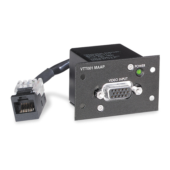
Installation, cont’d Rear Panel Connectors VTT001 MAAP VTT001 VTT001 AAP Figure 2-1 — VTT001 MAAP, VTT001, and VTT001 AAP rear panel views The VTT001 MAAP/VTT001 AAP and VTT001 models differ in how they are mounted. See “Mounting” in this chapter. - Page 15 Transmitter output connector — A female RJ-45 connector on a 3" pigtail for the VTT001 MAAP and VTT001 AAP models, or within the VTT001 model. Plug this connector to the UTP cable going to the receiver. CAUTION Do not connect the transmitter to a computer data or telecommunications network.
-
Page 16: Front Panel Connector And Indicator
Power input jack — Connect the included 12 VDC external power supply to this female jack. The VTT001 and the VTR001 use this power input connector. See the notes and warning for Power plug... - Page 17 Receiver video output connector — A female 15-pin HD VGA connector for all models. Connect a monitor, LCD projector, or other display device to output an RGBHV or RGBS video signal. Power LED indicator — The LED lights green whenever power is applied. VTT001 and VTR001 • Installation...
-
Page 18: Cabling And Setup
Installation, cont’d Cabling and Setup To install the VTT001 MAAP, VTT001 AAP, VTT001 models and the VTR001 MAAP, VTR001 AAP, VTR001 models, follow these steps: Turn all of the equipment off and, if applicable, disconnect it from the power source. -
Page 19: Compatibility With Other Extron Products
TP R AV TP R BNC AV TP R 15HD A VTT001 series A = RGB video only B = incompatible The VTT001 series and VTR001 series will not power the compatible Extron products remotely. VTT001 and VTR001 • Installation... -
Page 20: Cable Testing
A/V UTP cable minimizes pair skew to the point that equalization is not required. Skew exists between pairs when the physical length of one wire pair is different from another. As the transmission cable length VTT001 and VTR001 • Installation... - Page 21 • Install an Extron Skew Equalizer, SEQ 100 15HD (part #60-676-01) or SEQ 100 BNC (part #60-675-01), on the receiver’s video output and adjust the skew for the leading video image. VTT001 and VTR001 • Installation...
-
Page 22: Sharpness Adjustment
Mounting The mountable transmitter (VTT001 MAAP) and mountable receiver (VTR001 MAAP) may be attached to a wall with either a stud-mounted wall box or with a wall mounting bracket (Extron part # 70-163-xx). Both installations require the double spaced MAAP connector frame, such as the CPM101). - Page 23 Wall Stud Wall Stud Installation Cable Installation Cable Cable Clamp Cable Clamp Screws or Nails Screws or Nails Figure 2-7 — Attaching a wall box to a wall stud VTT001 and VTR001 • Installation 2-11...
-
Page 24: Wall Box Mounting
CPM101 Mounting Frame Figure 2-8 — Attaching the mounting frame to a wall Connect the video input and output devices to the front faceplates of the transmitter and receiver, respectively. Power on all devices. VTT001 and VTR001 • Installation 2-12... -
Page 25: Wall Bracket Mounting
Backing Clip Extron 70-163-xx Wall Mounting Bracket I N P Extron VTT001 MAAP Twisted Pair Transmitter Extron CPM101 Mounting Frame Figure 2-9 — Attaching the mounting frame to the wall mounting bracket VTT001 and VTR001 • Installation 2-13... -
Page 26: Aap Mounting
Power on all devices. AAP mounting The AAP versions of the VTT001 (VTT001 AAP) and VTR001 (VTR001 AAP) are mounted to the Extron AAP panel by inserting the two AAP studs through the panel mounting holes and attaching the nuts. -
Page 27: Rack Mounting
(e.g. use of power strips). Rack mounting Various 1U rack space frames accommodate the VTT001 MAAP, VTT001 AAP, VTR001 MAAP, and VTR001 AAP modules. The CPM133 is a one-third rack width frame that can be mounted to the IN9080 rack mount shelf. - Page 28 Screws Figure 2-11 — CPM112R A/V connector frame mounted directly to a rack For mounting the VTT001 MAAP/VTR001 MAAP to a rack mount shelf, mount the transmitter/receiver module(s) to the A/V connector frame, then attach the frame to the shelf. See the example in figure 2-12.
- Page 29 Attach the video input and output devices to the front faceplates of the transmitter and receiver, respectively. Power on all devices. VTT001 and VTR001 • Installation 2-17...
- Page 30 Installation, cont’d For mounting the VTT001 AAP/ VTR001 AAP to a rack, mount the AAP module(s) to the Extron AAP frame, then attach the frame to the rack. See the example in figure 2-13. #10-32 Screw/ Nylon Captive Cap Washer...
-
Page 31: Specifications
VTT001/VTR001 Appendix Reference Information Specifications Parts List... - Page 32 VTR001 series ....RGBHV, RGBS Connectors VTT001 ......1 RJ-45 female jack VTT001 MAAP/AAP ..1 RJ-45 female on a 3" (7.6 cm) pigtail VTR001 series ....(1) 15-pin HD female Nominal level ....... 0.7 V p-p for RGB Minimum/maximum levels ..0.3 V to 1.45 Vp-p Impedance ........
- Page 33 W x 0.3 cm D) (double space high AAP plate) VTT001 series Device ......1.4" H x 1.4" W x 1.4" D (3.5 cm H x 3.5 cm W x 3.5 cm D) (Depth excludes connectors.) VTT001 and VTR001 • Reference Information...
- Page 34 Safety ......... CE, c-UL, UL EMI/EMC ......CE, C-tick, FCC Class A, ICES, VCCI MTBF ..........30,000 hours Warranty ........3 years parts and labor All nominal levels are at ±10%. Specifications are subject to change without notice. VTT001 and VTR001 • Reference Information...
-
Page 35: Vtt001 Maap And Vtr001 Maap
Parts List VTT001 MAAP and VTR001 MAAP* Description Part number VTT001 MAAP wall mount transmitter - black 70-284-11 VTT001 MAAP wall mount transmitter - white 70-284-21 VTR001 MAAP wall mount receiver - black 70-285-11 VTR001 MAAP wall mount receiver - white 70-285-21 * The MAAP models mount into MAAP (mini AAP) panels. -
Page 36: Skew-Free A/V Utp Cables
AAP 201 frame - half rack width, 1U (black) 60-302-02 AAP 202 frame - half rack width, 2U (black) 60-303-02 AAP 301 frame - full rack width, 1U (black) 60-632-02 AAP 302 frame - full rack width, 1U (black) 60-633-02 VTT001 and VTR001 • Reference Information... - Page 37 VTT001 and VTR001 • Reference Information...
- Page 38 Reference Information, cont’d VTT001 and VTR001 • Reference Information...
- Page 39 fi tness for any particular use. In no event will Extron Electronics be liable for direct, indirect, or consequential damages resulting from any defect in this product even if Extron Electronics has been advised of such damage.
- Page 40 Inside USA / Canada Only Inside Europe Only Inside Asia Only Inside China Only Inside USA / Canada Only +1.919.863.1794 +31.33.453.4040 +65.6383.4400 +86.21.3760.1568 +1.714.491.1500 +1.919.863.1797 FAX +31.33.453.4050 FAX +65.6383.4664 FAX +86.21.3760.1566 FAX +1.714.491.1517 FAX © 2009 Extron Electronics. All rights reserved.
Need help?
Do you have a question about the VTT001 and is the answer not in the manual?
Questions and answers