Extron electronics VTT001 User Manual
Twisted pair transmitter and receiver
Hide thumbs
Also See for VTT001:
- Specifications (2 pages) ,
- Setup manual (1 page) ,
- User manual (40 pages)
Table of Contents
Advertisement
Quick Links
Download this manual
See also:
Setup Manual
Advertisement
Table of Contents

Related Manuals for Extron electronics VTT001


Summary of Contents for Extron electronics VTT001
- Page 1 User Guide Twisted Pair VTT001 and VTR001 Twisted Pair Transmitter and Receiver 68-760-01 Rev. H 06 11...
- Page 2 Safety Instructions • English Warning Power sources • This equipment should be operated only from the power source indicated on the product. This This symbol is intended to alert the user of important operating and mainte- equipment is intended to be used with a main power system with a grounded (neutral) conductor. The third nance (servicing) instructions in the literature provided with the equipment.
- Page 3 This unit was tested with shielded cables on the peripheral devices. Shielded cables must be used with the unit to ensure compliance with FCC emissions limits. For more information on safety guidelines, regulatory compliances, EMI/EMF compliance, accessibility, and related topics, click here. VTT001 and VTR001 User Guide • FCC Notice...
- Page 4 From the menu, select File Click the button. Copyright © 2011 Extron Electronics. All rights reserved. Trademarks All trademarks mentioned in this guide are the properties of their respective owners. VTT001 and VTR001 User Guide • Conventions...
-
Page 5: Table Of Contents
Preparing the Wall Box ........10 Reference Information ........18 Specifications ............ 18 Parts List ............20 VTT001 MAAP and VTR001 MAAP ....20 VTT001 and VTR001 Tabletop ....... 20 VTR001 AAP ..........20 Included Parts ..........20 Skew-Free A/V UTP Cables ......20 Other Accessories ......... -
Page 6: Introduction
Introduction The Extron VTT001 twisted pair (TP) transmitter series and VTR001 twisted pair receiver ® series provide a system for sending VGA, RGBHV, and RGBS signals up to 500 feet (150 meters) over Extron Skew-Free™ A/V UTP cable. They can also send these signals over CAT 5/5e/6 UTP cable. -
Page 7: Features
TP T 15HD 45, TPX 88, TPX 88 A, and TP T BNC DA4. Remote power capability — Both transmitter and receiver can be powered remotely • when cable runs are 300 feet or less. VTT001 and VTR001 User Guide • Introduction... -
Page 8: Installation
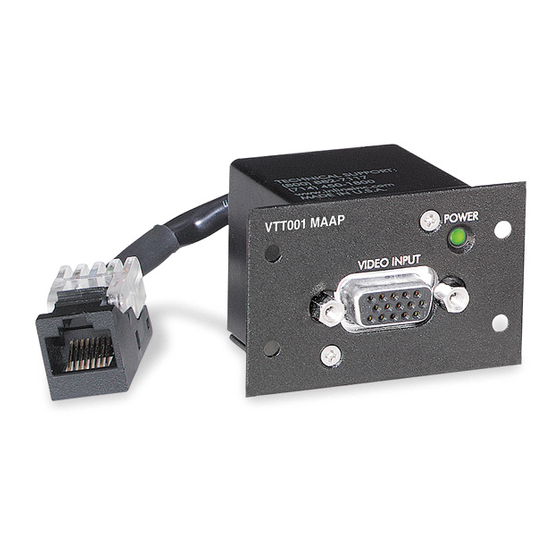
VTT001 MAAP VTT001 VTR001-VTT001 Panel Layout 2 Figure 1. VTT001 MAAP and VTT001 Rear Panel Views NOTE: The VTT001 MAAP and VTT001 models differ in how they are mounted (see Mounting). VTR001 MAAP VTR001 VTR001 AAP Figure 2. VTR001 MAAP, VTR001, and VTR001 AAP Rear Panel Views... - Page 9 Ä Transmitter output connector — A female RJ-45 connector on a 3 inch pigtail for the VTT001 MAAP, or within the VTT001 model. Plug this connector to the UTP cable going to the receiver. CAUTION: Do not connect the transmitter to a computer data or telecommunications network.
- Page 10 Power Connector wiring.eps transmitter and receiver. É Power input jack — Connect the included 12 VDC external power supply to this female jack. The VTT001 and the VTR001 use this power input connector (see the note, Ç caution, and warning for above).
-
Page 11: Front Panel Connector And Indicator
VTR001-VTT001 Panel Layout 2 Front Panel Connector and Indicator VTT001 MAAP VTT001 MAAP Figure 3. VTT001 MAAP and VTT001 Front Panel Views VTR001 MAAP VTR001 MAAP VTR001 AAP VTR001 AAP OUTPUT OUTPUT VTR001 AAP VTR001 AAP Figure 4. VTR001 MAAP, VTR001, and VTR001 AAP Front Panel Views... -
Page 12: Cabling And Setup
Cabling and Setup To install the VTT001 MAAP and VTT001 models and the VTR001 MAAP, VTR001 AAP, and VTR001 models, follow these steps: Turn all of the equipment off and, if applicable, disconnect it from the power source. Connect the RJ-45 connectors of the transmitter and receiver to either end of the UTP... -
Page 13: Compatibilty With Other Extron Products
Compatibilty with Other Extron Products The VTT001 series and VTR001 series products can communicate with other Extron products. The following tables indicate how the products interact. TP T 15HD A... -
Page 14: Equalizing Pair Skew
Adjust this control using the included adjustment tool (Extron part number: 100-014-01LF) while viewing the displayed image to obtain the optimum picture sharpness. Turning the control clockwise increases peaking and turning it counterclockwise decreases peaking. VTT001 and VTR001 User Guide • Installation... -
Page 15: Mounting
Mounting The mountable transmitter (VTT001 MAAP) and mountable receiver (VTR001 MAAP) may be attached to a wall with either a stud-mounted wall box or with a wall mounting bracket (Extron part number: 70-163-xx). Both installations require the double spaced MAAP connector frame, such as the CPM101). The transmitter/receiver module can also be attached to any Extron MAAP device that accepts a double spaced A/V connector panel, or the modules may be rack mounted. - Page 16 Mount the modules onto a faceplate or frame, then cable and test the transmitter/ receiver modules before fastening it into the wall box or bracket. The cables are inaccessible after installation. VTT001 and VTR001 User Guide • Installation...
- Page 17 Mounting Frame Figure 8. Attaching the Mounting Frame to the Wall Box Connect the video input and output devices to the front faceplates of the transmitter and receiver, respectively. Power on all devices. VTT001 and VTR001 User Guide • Installation...
- Page 18 Mounting Frame Figure 9. Attaching the Mounting Frame to the Wall Mounting Bracket Attach the video input and output devices to the front faceplates of the transmitter and receiver, respectively. Power on all devices. VTT001 and VTR001 User Guide • Installation...
- Page 19 Reliable earthing (grounding) — Maintain reliable grounding of rack-mounted equipment. Pay particular attention to supply connections other than direct connections to the branch circuit (that is, use of power strips). VTT001 and VTR001 User Guide • Installation...
- Page 20 Rack mounting Various 1U rack space frames accommodate the VTT001 MAAP, VTR001 MAAP, and VTR001 AAP modules. The CPM133 is a one-third rack width frame that can be mounted to the IN9080 rack mount shelf. The CPM112R, as shown below, is a full rack width frame that holds six double sized modules.
- Page 21 For mounting the VTT001 MAAP or VTR001 MAAP to a rack mount shelf, mount the transmitter/receiver modules to the A/V connector frame, then attach the frame to the shelf, as shown below. RSB 129 (60-190-01) Rack Mount Shelf CPM133 (60-584-15) or...
- Page 22 #10-32 Screw/ Nylon Captive Cap Washer #4-40 Nut with Captive Washer VTR001 AAP Twisted Pair Transmitter AAP 301 Architectural Frame Figure 13. Extron AAP 301 Frame Mounted Directly to a Rack VTT001 and VTR001 User Guide • Installation...
-
Page 23: Reference Information
1 female RJ-45 jack on a 3" (7.6 cm) pigtail Video input Number/signal type VTT001 series ......RGBHV, RGBS VTR001 series ......1 set of proprietary analog signals from a VTT001 model Connectors VTT001 series ......1 female 15-pin HD VTR001 ........1 female RJ-45 jack VTR001 MAAP/AAP .... - Page 24 EMI/EMC ......... CE, C-tick, FCC Class A, ICES, VCCI MTBF ..........30,000 hours Warranty ........3 years parts and labor NOTE: All nominal levels are at ±10%. NOTE: Specifications are subject to change without notice. VTT001 and VTR001 User Guide • Reference Information...
-
Page 25: Parts List
26-570-05 UTP23SF-4P/50 50' preterminated (plenum) 26-570-06 UTP23SF-4P/75 75' preterminated (plenum) 26-570-07 UTP23SF-4/12 12' preterm. (non-plenum) 26-569-03 UTP23SF-4/25 25' preterm. (non-plenum) 26-569-04 UTP23SF-4/50 50' preterm. (non-plenum) 26-569-06 NOTE: Other cable lengths are available. VTT001 and VTR001 User Guide • Reference Information... -
Page 26: Other Accessories
AAP 201 frame - half rack width, 1U (black) 60-302-02 AAP 202 frame - half rack width, 2U (black) 60-303-02 AAP 301 frame - full rack width, 1U (black) 60-632-02 AAP 302 frame - full rack width, 1U (black) 60-633-02 VTT001 and VTR001 User Guide • Reference Information... - Page 27 Extron Electronics makes no further warranties either expressed or implied with respect to the product and its quality, performance, merchantability, or fitness for any particular use. In no event will Extron Electronics be liable for direct, indirect, or consequential damages resulting from any defect in this product even if Extron Electronics has been advised of such damage.
Need help?
Do you have a question about the VTT001 and is the answer not in the manual?
Questions and answers