Advertisement
Quick Links
Advertisement

Related Manuals for Xilinx SP701


Summary of Contents for Xilinx SP701
- Page 1 SP701 Software Install and Board Setup June 2019 XTP552...
-
Page 2: Revision History
NOTICE OF DISCLAIMER: The information disclosed to you hereunder (the “Information”) is provided “AS-IS” with no warranty of any kind, express or implied. Xilinx does not assume any liability arising from your use of the Information. You are responsible for obtaining any rights you may require for your use of this Information. - Page 3 SP701 Software Install and Board Setup Xilinx SP701 Board ˃ Software Requirements ˃ SP701 Hardware Setup ˃ UART Driver Install ˃ Terminal Setup ˃ Clock Setup ˃ Ethernet Setup ˃ Optional Hardware Setup ˃ References ˃ Note: This presentation applies to the SP701...
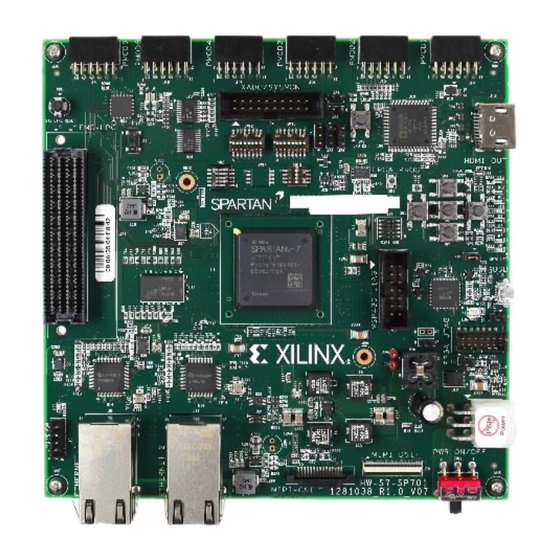
- Page 4 Xilinx SP701 Board...
-
Page 5: Software Requirements
Software Requirements Xilinx Vivado Design Suite 2018.3, HL System Edition with SDK ˃ Note: Presentation applies to the SP701... - Page 6 SP701 Hardware Setup Kit Hardware contents ˃ SP701 Board Micro USB cable Ethernet cable Power supply Note: Presentation applies to the SP701...
- Page 7 USB UART connector (J5) on the SP701 board Connect this cable to your PC ˃ Connect the power supply to the ˃ SP701 (J30) Connect this power supply to a power outlet Note: Presentation applies to the SP701...
- Page 8 Control Panel → System → Device Manager The COM Port numbers will vary from system to system The COM Port numbers may be out of order These COM Port Numbers will be used in several of the tutorials ˃ Note: Presentation applies to the SP701...
-
Page 9: Terminal Setup
Board Power must be on before starting Tera Term ˃ Start the Terminal Program ˃ Set the baud to 115200 You may need to try the other two port numbers, as the COM Port numbers do not always enumerate in order Note: Presentation applies to the SP701... -
Page 10: Ethernet Setup
Ethernet Setup Open the Windows Control Panel ˃ Set to View by Category Click on “View network status and tasks” ˃ Note: Presentation applies to the SP701... - Page 11 Ethernet Setup Click on “Change adapter settings” ˃ Note: Presentation applies to the SP701...
- Page 12 Ethernet Setup Right-click on the Gigabit Ethernet Adapter that you will be using for this ˃ test and select Properties Note: Presentation applies to the SP701...
- Page 13 Ethernet Setup Click Configure ˃ Set the Link Speed & Duplex to Auto Negotiation then click OK Note: Presentation applies to the SP701...
- Page 14 Ethernet Setup Reopen the properties after the last step ˃ Double-click the Internet Protocol Version 4 ˃ Set your host (PC) to this IP Address: ˃ Note: Presentation applies to the SP701...
- Page 15 Optional Hardware Setup Attach a Whizz FMC XM107 board to the FMC LPC connector (J21) ˃ Available through Whizz Systems ˃ Note: Presentation applies to the SP701...
- Page 16 Optional Hardware Setup Using a common HDMI cable, connect ˃ an HDMI Monitor to the HDMI port (J13) Tested with ViewSonic VP2780-4K ˃ monitor Note: Presentation applies to the SP701...
- Page 17 Optional Hardware Setup MIPI display and camera ˃ Camera: Digilent Pcam 5C connected to J8 Display: Chunghwa CLAA101FP05 cable connected to J20 Note: Presentation applies to the SP701...
- Page 18 Optional Test Equipment Shunt jumpers on PMODs ˃ 6ea for PMOD headers: Suggested MNT-102-BK-G and S2021EC-06-ND; combined as shown to the rightmost Note: Presentation applies to the SP701...
- Page 19 References...
- Page 20 References Vivado Release Notes ˃ Vivado Design Suite User Guide - Release Notes – UG973 https://www.xilinx.com/support/documentation/sw_manuals/xilinx2018_3/ ‒ ug973-vivado-release-notes-install-license.pdf Vivado Design Suite 2018 - Vivado Known Issues https://www.xilinx.com/support/answers/70860.html ‒ Vivado Programming and Debugging ˃ Vivado Design Suite Programming and Debugging User Guide – UG908 https://www.xilinx.com/support/documentation/sw_manuals/xilinx2018_3/...
- Page 21 Documentation...
- Page 22 ˃ Spartan 7 FPGA SP701 Evaluation Kit https://www.xilinx.com/products/boards-and-kits/ek-s7-sp701-g.html ‒ SP701 Board User Guide – UG1319 ‒ https://www.xilinx.com/support/documentation/boards_and_kits/sp701/ug1319-sp701-eval- bd.pdf SP701 Evaluation Kit Quick Start Guide User Guide – XTP540 ‒ https://www.xilinx.com/support/documentation/boards_and_kits/sp701/xtp540-sp701- quickstart.pdf SP701 - Known Issues Master Answer Record ‒ https://www.xilinx.com/support/answers/72092.html...
Need help?
Do you have a question about the SP701 and is the answer not in the manual?
Questions and answers