Rayburn Cookmaster 300K Installation & Servicing Instructions Manual
Oil-fired cooker
Hide thumbs
Also See for Cookmaster 300K:
- User instructions (9 pages) ,
- User instructions (8 pages) ,
- Installation & servicing instructions manual (12 pages)
Table of Contents
Advertisement
EINS 511985
Better than you ever imagined
Installation & Servicing Instructions
for Rayburn Cookmaster 300K and
Rayburn Cookmaster Plus 308K
Consumer Protection Act 1987
As responsible manufacturers we take care to make sure that our products are designed and constructed to meet
the required safety standards when properly installed and used.
Any alteration that is not approved by Aga-Rayburn, could invalidate the approval of the
IMPORTANT NOTICE:
appliance, operation of the warranty and could also affect your statutory rights.
Control of Substances - Health and Safety Important
This appliance may contain some of the materials that are indicated. It is the Users/Installers responsibility to
ensure that the necessary personal protective clothing is worn whenhandling, where applicable, the pertinent
parts that contain any of the listed materials that could be interpreted as being injurious to health and safety, see
below for information.
Firebricks, Fuel beds, Artificial Fuels -
when handling use disposable gloves.
Fire Cement -
Glues and Sealants -
exercise caution - if these are still in liquid form use face mask and disposable gloves.
Glass Yarn, Mineral Wool, Insulation Pads, Ceramic Fibre, Kerosene/Gas Oil -
may be irritating to skin, eyes, nose and throat. When handling avoid inhaling and contact with skin or eyes. Use
disposable gloves, face-masks and eye protection. After handling wash hands and other exposed parts. When
disposing of the product, reduce dust with water spray, ensure that parts are securely wrapped.
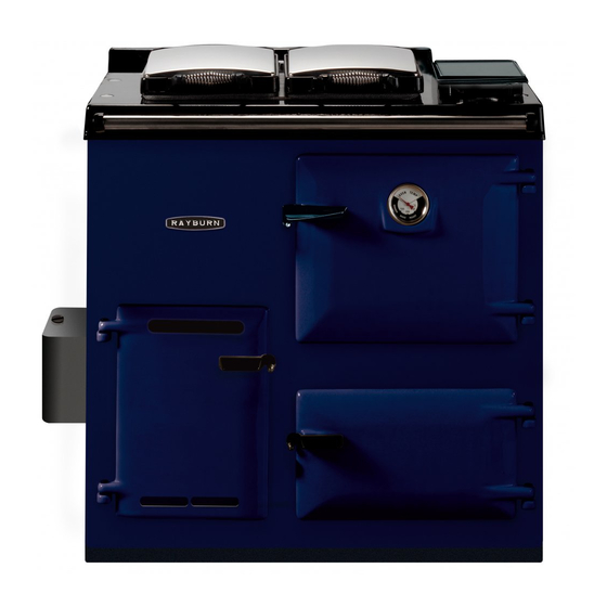
The Rayburn Cookmaster Plus 308K is a cooker providing domestic hot water and cooking facilities. It is available
with a vertical flue and outlet only, with the oil burner operating on natural draught.
The boiler is designed for use in an open vented water system only, with gravity D.H.W. primaries.
file://\\server1\docs\NetCDs\Aga%20Product%20Information%20Spares%20and%20Tec...
Oil-Fired Cooker
when handling use disposable gloves.
INTRODUCTION
Page 1 of 23
10/05 EINS 511985
may be harmful if inhaled,
26/10/2006
Advertisement
Table of Contents

Related Manuals for Rayburn Cookmaster 300K


Summary of Contents for Rayburn Cookmaster 300K
- Page 1 INTRODUCTION The Rayburn Cookmaster Plus 308K is a cooker providing domestic hot water and cooking facilities. It is available with a vertical flue and outlet only, with the oil burner operating on natural draught.
- Page 2 The heat exchanger is manufactured from a high quality stainless steel and where permitted by local water authorities may be used on direct hot water systems, although it is preferable to use the indirect system. Alternatively, the Rayburn Cookmaster 300K is a non-boiler model. However with this model the IDLING TEMPERATURE MAY BE HIGHER .
-
Page 3: Installation Instructions
EINS 511985 Page 3 of 23 DESN 511031 PLEASE NOTE: IT IS ADVISABLE TO CHECK THE WIDTH OF YOUR APPLIANCE BEFORE FINALLY FIXING ANY KITCHEN UNITS SINCE ENAMELLED CAST IRON CAN VARY IN SIZE Fig.1 Oil Storage tank and pipeline details DESN 510210 INSTALLATION INSTRUCTIONS The installation of the appliance must be in accordance with the relevant requirements of the current Building Regulations, current I.E.E. - Page 4 EINS 511985 Page 4 of 23 It should be in accordance also with any relevant requirements of the Local Authority and the relevant recommendations of the following current British Codes of Practice: BS.5410 Installation of oil fired space heating and hot water supply purposes. Boilers of rated output not exceeding 44kW.
- Page 5 EINS 511985 Page 5 of 23 FLUE SYSTEM - See Fig.2 Detailed recommendations for fluing are given in the current Building Regulations J/1/2/3. The following notes are intended to give a general guidance:-The cross sectional area of the flue serving the appliance must not be less than the area of the flue outlet of the appliance and be at least 4.5m high.
- Page 6 EINS 511985 Page 6 of 23 High Chimney Draughts A well sealed, tall exposed chimney on a hill, is an instance where generated draughts could be excessive and must be controlled. file://\\server1\docs\NetCDs\Aga%20Product%20Information%20Spares%20and%20Tec... 26/10/2006...
- Page 7 EINS 511985 Page 7 of 23 Fig.2 Flue Layouts Should this occur, a flue stabilizer must be fitted either in the flue pipe or chimney, but in the same room as the appliance. Flue Gas Temperature file://\\server1\docs\NetCDs\Aga%20Product%20Information%20Spares%20and%20Tec... 26/10/2006...
-
Page 8: Air Supply
EINS 511985 Page 8 of 23 Typical flue gas temperature under normal operating conditions are 200 - 250°C. Maximum flue gas temperature typically 330°C (308K at maximum setting). UNDER NO CIRCUMSTANCES SHOULD 90° BENDS BE USED IN THE FLUE SYSTEM AIR SUPPLY Detailed recommendations for air supply are given in the current Building Regulations J/1/2/3. - Page 9 EINS 511985 Page 9 of 23 (Manufactured by Albion Cylinders) complying with the BS.1566, should be insulated, preferably with not less than 75mm thick mineral fibre or its equivalent, and fixed vertically as near as possible to the appliance. The water draw-off pipes to the taps must be dead leg connection from the vent expansion pipe.
-
Page 10: Preliminary Installation
EINS 511985 Page 10 of 23 The combined appliance is floor-mounted and the space in which the appliance is to be fitted must have the following minimum dimensions:- Between wall and L.H. side of appliance 150mm Between wall and R.H. side of appliance 10mm, OR IF THE WALL PROJECTS BEYOND THE FRONT OF THE APPLIANCE - 50mm (See Fig. -
Page 11: Site Location
EINS 511985 Page 11 of 23 Where the cooker is to stand in a recess or against a wall which is to be tiled, in no circumstances should the tiles overlap the cooker top plate. Fig. 5 DESN 510454 A SITE LOCATION The handrail brackets are held on the front ends of the cooker top-plate casting. -
Page 12: Burner Installation
EINS 511985 Page 12 of 23 Pipe connections should made to the two Rp1 (1in BSP int) flow and return tappings in the boiler on the LH side of the appliance. Pipe connections should be made with Rp1 (1in BSP ext) x 28mm dia copper compression fittings or steel pipe nipples. - Page 13 EINS 511985 Page 13 of 23 Fig.6 Clearance Between Cooker and Combustion Wall DESN 510119 Fig .7 DESN 510827 NOTE: THE BURNER BASE MUST BE LEVEL. 4. Insert the copper oil feed pipe through the side of the cooker with the front end turned upward for connection to the burner base front elbow.
- Page 14 EINS 511985 Page 14 of 23 Fig.8 Burner assembly - 308K Boiler Model DESN 511029 Fig. 8A Burner assembly - 300K Non-Boiler Model file://\\server1\docs\NetCDs\Aga%20Product%20Information%20Spares%20and%20Tec... 26/10/2006...
- Page 15 EINS 511985 Page 15 of 23 CHECKING THE BURNER OIL LEVEL 1. Open all oil valves to allow oil into the oil control valve. It may be necessary to purge the oil line to prevent airlocking. 2. Depress the trip lever D on the front of the oil control valve A, and turn cooker oil control knob C to No.6 setting.
- Page 16 EINS 511985 Page 16 of 23 Fig. 10 Oil should enter the burner base in due course and after about 10-15 minutes, the depth of the oil should have settled to a static depth of 5-6mm deep where oil enters the oilways of the burner base. To correct the oil depth, adjust the oil control valve height via the adjusting screws between the valve and mounting bracket.
- Page 17 EINS 511985 Page 17 of 23 Fig. 11 Fig. 12 DESN 511910 General a. Turn oil valve control knob to OFF, disconnect the copper pipe connection at the burner base and file://\\server1\docs\NetCDs\Aga%20Product%20Information%20Spares%20and%20Tec... 26/10/2006...
- Page 18 EINS 511985 Page 18 of 23 withdraw. Draw off the oil in the burner base. Alternatively the oil can be sucked out using an aspirator. b. Fit the burner wicks, vapour chamber, sealing plate and perforated shell assembly with top baffle assembly, checking that the shell assembly seats airtightly on the burner base.
- Page 19 EINS 511985 Page 19 of 23 A spillage test must be carried out after 30 minutes as follows:- By holding a smoke match so that match head is approximately 3mm to 5mm inside the lower edge of the draught diverter (See Fig.
- Page 20 It is important that a 6 monthly service be carried out by a competent Service Engineer and it is recommended that a contract be made with such an Engineer. Your Rayburn Stockist will provide advice on the location of the nearest Servicing Engineer.
- Page 21 EINS 511985 Page 21 of 23 Before commencing any servicing, isolate the oil supply from the tank and ensure the oil control valve front trip lever if OFF . STANDARD BI-ANNUAL SERVICE SCHEDULE a. Service clean of cooker boiler heat exchanger flueways. b.
- Page 22 EINS 511985 Page 22 of 23 h. Replace hotplate ensuring that the underside fins lie over the combustion chamber. i. Replace the oil burner assembly within the combustion chamber, and re-connect the copper oil pipe to the elbow. NOTE: ENSURE THE COPPER PIPE IS NOT KINKED, OTHERWISE AIR LOCKING WILL PREVAIL. TO CHECK THE OIL CONTROL VALVE 4.
- Page 23 EINS 511985 Page 23 of 23 file://\\server1\docs\NetCDs\Aga%20Product%20Information%20Spares%20and%20Tec... 26/10/2006...
Need help?
Do you have a question about the Cookmaster 300K and is the answer not in the manual?
Questions and answers
burning rate for a 300k
The Rayburn Cookmaster 300K operates at a low fire rate continuously when not required for cooking. When cooking is needed, the burner operates at a high fire rate, which is adjusted using the control knob.
This answer is automatically generated