Table of Contents
Advertisement
Better than you ever imagined
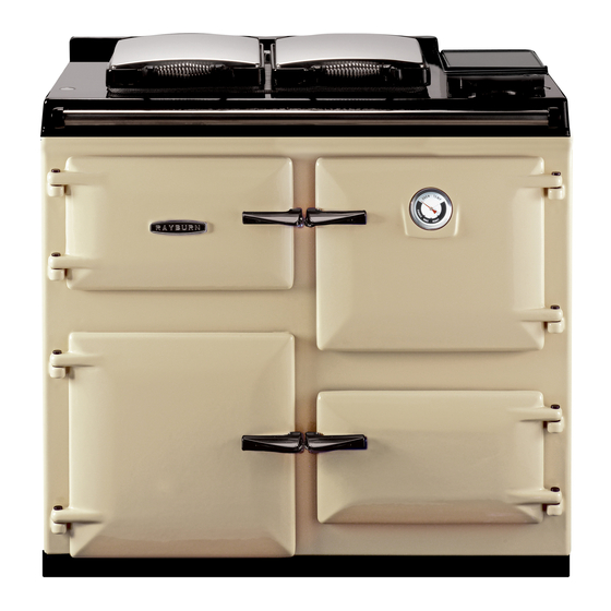
Heatranger 480AG (CF)/480AL (CF)
Consumer Protection
As responsible manufacturers we take care to make sure that our
products are designed and constructed to meet the required safety
standards when properly installed and used.
IMPORTANT NOTICE: PLEASE READ THE ACCOMPANYING
WARRANTY.
Any alteration that is not approved by Aga could invalidate the
approval of the appliance, operation of the warranty and could affect
your statutory rights.
Important
This appliance may contain some of the materials that are indicated
It is the Users/Installers responsibility to ensure that the necessary
personal protective clothing is worn when handling where
INTRODUCTION
THIS
APPLIANCE
MUST
ACCORDANCE WITH THE RULES IN FORCE AND
USED ONLY IN A SUFFICIENT VENTILATION SPACE.
USE ONLY ON FULLY PUMPED SYSTEMS
This Rayburn Gas combination appliance is combined
cooker and hot water boiler providing central heating and
domestic hot water in addition to special cooking
facilities. It is available in open flue form, operating on
natural draught, the boiler being designed for use in fully
pumped, open or sealed systems. Two separate
independent controlled gas burners provide heat. One
PLEASE READ THESE INSTRUCTIONS BEFORE INSTALLING THE APPLIANCE
raywarranty@aga-web.co.uk
BE
INSTALLED
IN
applicable, the pertinent parts that contain any of the listed materials
that could be interpreted as being injurious to health and safety, see
below for information.
Firebricks, Fuel beds, Artificial Fuels - when handling use
disposable gloves.
Fire cement - when handling use disposable gloves.
Glues and Sealants - exercise caution - if these are still in liquid form
use face mask and disposable gloves.
Glass Yarn, Mineral Wool, Insulation Pads, Ceramic Fibre,
Kerosene/Gas Oil - may be harmful if inhaled. May be irritating to
skin, eyes, nose and throat. When handling avoid contact with skin
or eyes. Use disposable gloves, face-masks and eye protection.
After handling wash hands and other exposed parts.
disposing of the product, reduce dust with water spray, ensure that
parts are securely wrapped.
burner for central heating boiler section, providing heating
and hot water, whilst the other burner provides heat to
the cooker.
REMEMBER, when replacing a part on this appliance,
use only spare parts that we require. Do not use
reconditioned or copy parts that have not been
clearly authorised by Aga.
REGULATIONS
In the interests of safety all gas appliances should be
installed by competent persons, in accordance with the
regulations in force.
1
Installation
and
Servicing
Instructions
FOR USE IN GB & IE
DESN 512129
07/05 EINS 512112
When
Advertisement
Table of Contents

Related Manuals for Rayburn Heatranger 480AG (CF)


Summary of Contents for Rayburn Heatranger 480AG (CF)
- Page 1 USE ONLY ON FULLY PUMPED SYSTEMS clearly authorised by Aga. This Rayburn Gas combination appliance is combined REGULATIONS cooker and hot water boiler providing central heating and domestic hot water in addition to special cooking facilities.
-
Page 2: Table Of Contents
Contents SECTION CONTENTS PAGE SITE REQUIREMENTS SPECIFICATIONS LOCATION GAS SUPPLY ELECTRICAL SUPPLY CONTROLS FLUE SYSTEM AIR REQUIREMENTS WATER CIRCULATION SYSTEM INSTALLATION INSTRUCTIONS CLEARANCES PRELIMINARY INSTALLATION GAS CONNECTION WATER CONNECTIONS SYSTEM SUITABILITY COMBUSTION DISCHARGE SAFETY DEVICE ELECTRICAL CONNECTIONS ELECTRICAL CHECKS ELECTRICAL INSTALLATION COMMISSIONING WATER CIRCULATION SYSTEM COMMISSIONING THE COOKER AND BOILER... -
Page 3: Specifications
Specifications R 1/2 (1/2” BSP TAPER) NOTE: IT IS ADVISABLE TO CHECK THE ACTUAL SIZE/WIDTH OF YOUR CUPBOARDS BEFORE FINALLY FIXING ANY KITCHEN UNITS SINCE ENAMELLED CAST IRON CAN VARY IN SIZE. TOTAL BOILER COOKER 480AG NAT. GAS (G20) MIN. MAX. -
Page 4: Location
Site Requirements LOCATION GAS SUPPLY The appliance must be installed on a solid level floor or base Pipework from the meter to the appliance must be of of incombustible material which is capable of supporting the adequate size. It is recommended that ø22mm minimum total weight. - Page 5 10mm 10mm WATER CONNECTIONS: INSTALLER MUST MAKE PROVISION TO GAIN ACCESS TO 22mm COPPER FLOW AND RETURN PIPE DURING INSTALLATION R 1/2 (1/2” BSP) GAS CONNECTION MINIMUM GAP ON RIGHT HAND SIDE MINIMUM GAP ON LEFT HAND SIDE Fig. 1A 50mm WALL PROJECTING THE FRONT OF THE APPLIANCE Fig.
-
Page 6: Controls
Site Requirements If a baffle plate, etc is fitted in the flue it must be removed CONTROLS before connecting the appliance to, or inserting a liner into the flue. Independent temperature controls with time switch The flue should terminate in accordance with relevant control are recommended for providing temperature recommendations. -
Page 7: Water Circulation System
Site Requirements WATER CIRCULATION SYSTEM In a combined central heating and domestic hot water system, the hot water storage vessel must be of the indirect cylinder type. The hot water storage vessel should be insulated with not less than 75mm thick mineral fibre or its equivalent. -
Page 8: Clearances
Installation Instructions CLEARANCES The appliance is floor mounted. The space in which the appliance is to be fitted must have the following minimum dimensions:- Between wall and LH side of appliance - 10mm Between wall and RH side of appliance - 10mm* *SHOULD THE WALL PROJECT BEYOND THE FRONT OF THE APPLIANCE, WHEN IT MUST BE INCREASED TO 50MM (SEE FIG. - Page 9 Installation Instructions Site Location 1. Remove the appliance assembly from the transit wooden pallet by the temporary location of a sloping ramp board between the pallet and the floor. With the appliance on the floor, lift the front of the appliance (manually or crowbar) and insert a 32mm x 1m long tube between the front of the appliance base plate and the floor.
-
Page 10: Gas Connection
Installation Instructions GAS CONNECTION 1. Connect the gas supply to the 1/2” BSP tapered thread on the left hand side of the appliance (See Specifications, page 3). 2. Test the whole of the gas installation including the meter and purge in accordance with the relevant recommendations. -
Page 11: Electrical Connections
Installation Instructions ELECTRICAL CONNECTIONS Supply cable - PVC insulated three core 85˚C rated 300/500V .75mm To connect the electrical wiring to the appliance. Make electrical connections to terminal strip as wiring diagram. Remove the plinth cover at the bottom of the appliance (See Fig. - Page 12 Installation Instructions FIG. 10...
-
Page 13: Electrical Installation
Commissioning ELECTRICAL INSTALLATION LIGHTING THE PILOT Checks to ensure electrical safety should be carried out Boiler (see Fig. 11) by a competent person, ie. earth continuity, polarity and This appliance is fitted with an automatic ignition unit that resistance to earth. will light the main burner on demand. -
Page 14: Main Burner Lighting
Commissioning MAIN BURNER LIGHTING SEE FIG. 11 This appliance is fitted with a combustion discharge safety device which will switch off both main burners in adverse flue conditions. Before turning on main burners ensure that the manual reset button, which is located on the right hand side of the plinth is depressed. -
Page 15: Annual Servicing
Servicing ANNUAL SERVICING SERVICE SCHEDULE It is important for the correct operation of the appliance 1. Carry out a pre-service check noting any operational that servicing be carried out annually by a competent faults. person in accordance with gas safety regulations. 2. -
Page 16: Pre-Service Check
Servicing PRE-SERVICE CHECK Operate the appliance and system, noting any faults which may need to be corrected during service. WARNING: ISOLATE UNIT FROM ELECTRICITY SUPPLY AND TURN OFF GAS AT SERVICE COCKS BEFORE SERVICING. AFTER COMPLETING SERVICE ALWAYS CHECK FOR GAS SOUNDNESS AND CHECK THIS FUNCTION OF CONTROLS. -
Page 17: Burner Cleaning
Servicing BURNER CLEANING Boiler (See Fig. 13 and 14) Ensure isolation of electricity and gas supply. Remove plinth 3 screws (See Fig. 7). Disconnect ignitor lead C from the electronic ignition unit. Lift up electronic ignition unit J to release unit from gas valve. - Page 18 Servicing Cooker (see Fig. 15 and 16) Remove solenoid connector plug M. Undo union nut N. Undo two screws P. Remove the burner, complete with controls, from the unit (See Fig. 16). Brush the cooker burner top and check flame ports are clear.
-
Page 19: Heat Exchanger
Servicing HEAT EXCHANGER - Top access is gained through controls door aperture. SEE FIG. 17 & 17A BEFORE REMOVING SERVICE ACCESS COVERS ENSURE THAT ALL ELECTRICAL ACCESS TO THE APPLIANCE HAS BEEN SWITCHED OFF (SWITCH OFF AND REMOVE PLUG). SEE FIG. 17 & 17A 1. -
Page 20: Re-Assemble The Appliance
Servicing RE-ASSEMBLE THE APPLIANCE Re-assemble the appliance in reverse order. Refit boiler and cooker burner assemblies. Re-connect solenoid electrical supply to cooker burner assembly. Re-connect electronic ignition unit to the boiler gas valve. Re-connect ignitor lead to ignition unit. Replace hotplate. Test fully for gas soundness. -
Page 21: To Fit New Burner
Replacement of Parts - Cooker TO FIT NEW BURNER Follow instructions in section Burner Cleaning of Servicing Instructions and remove the cooker burner assembly. 1. Remove two pilot assembly screws. 2. Remove two screws securing injector bracket. a 3. Remove burner and transfer all ancillary items. 4. -
Page 22: Electrical Component Access
Replacement of Parts (Electrical Controls) ELECTRICAL COMPONENT ACCESS BEFORE REMOVING SERVICE ACCESS COVERS ENSURE THAT ALL ELECTRICAL ACCESS TO THE APPLIANCE HAS BEEN SWITCHED OFF (SWITCH OFF AND REMOVE PLUG). SEE FIG. 18 1. Remove the controls door and place in a safe position. 2. -
Page 23: Boiler Thermostat
Replacement of Parts (Electrical Controls) THERMOSTAT COOKER OVERHEAT CAPILLARIES THERMOSTAT COOKER THERMOSTAT CABLE CLAMP BOILER THERMOSTAT CAPILLARY EARTH POST BOILER THERMOSTAT FIG. 20 DESN 512148... -
Page 24: Cooker Overheat Thermostat
Replacement of Parts - Cooker TO FIT NEW OVEN CONTROL THERMOSTAT SEE FIG. 20 AND 21 Follow instructions section ELECTRICAL COMPONENT ACCESS, Steps 1 to 6. 1. Undo the two screws on the front of the chassis which holds the thermostat in place. 2. -
Page 25: Gas Valve
Replacement of parts - Boiler TO FIT NEW GAS VALVE See Fig. 22 Follow instructions in section Burner Cleaning of the Servicing Instructions and remove the boiler burner assembly. 1. Unscrew the pilot nut A on the gas valve and release. 2. -
Page 26: Burner
Replacement of parts - Boiler TO FIT NEW BURNER Follow instructions in section Burner Cleaning of THERMOSTAT PHIALS Servicing Instructions and remove the boiler burner assembly. 1. Remove four screws from burner mounting plate. 2. Remove four screws from flange elbow connecting gas valve to burner and separate assembly. -
Page 27: Boiler Overheat Thermostat
COMBUSTION NOTE: INCORRECT FITTING OF COMBUSTION DISCHARGE SAFETY DEVICE DISCHARGE DEVICE COULD LEAD TO COMBUSTION PHIAL CLIP PRODUCTS LEAKING INTO THE ROOM. COMBUSTION ONLY PARTS SUPPLIED BY RAYBURN MUST BE DISCHARGE USED. SAFETY DEVICE BAFFLE BOTTOM SPIGOT SPACERS - LONG FIG. -
Page 28: Sealed Systems
Sealed System SEALED SYSTEM REQUIREMENTS See Fig. 30 g. Mains Connection There shall be no connection to mains water supply or to a. The installation must comply with the regulations in the water storage cistern supplying domestic hot water, force. Maximum water 82˚C temperature. even though a non-return valve may be fitted, without the approval of the local water authority. -
Page 29: Sealed Systems
Sealed System Typical Sealed System THIS BY-PASS BALANCING VALVE SHOULD BE OF AN AUTOMATIC TYPE AND MUST HAVE AT LEAST 1.5 METRES OF 22mm PIPE EACH SIDE BETWEEN IT AND THE COOKER. ALTERNATIVELY, THE BYPASS LOOP CAN INCORPORATE A TOWEL RAIL CONTROLLED BY A NON- ADJUSTABLE BALANCING VALVE. - Page 32 For further advice or information contact your local distributor/stockist With Aga’s policy of continuous product improvement, the Company reserves the right to change specifications and make modifications to the appliance described at any time. Manufactured by Station Road Ketley Telford Shropshire TF1 5AQ England www.aga-web.co.uk...
Need help?
Do you have a question about the Heatranger 480AG (CF) and is the answer not in the manual?
Questions and answers