Table of Contents
Advertisement
Quick Links
(Not for use in Japan)
No. CP-SP-1453E
Flame Monitor
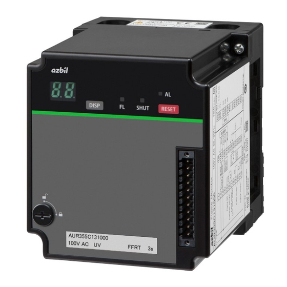
Model AUR355
User's Manual for
Communication Functions
Thank you for purchasing this product.
This manual contains information for
ensuring the safe and correct use of
the product.
Those designing or maintaining
equipment that uses this product
should first read and understand
this manual. This user's manual
contains information not only for
installation, but also for maintenance,
troubleshooting, etc. Be sure to keep it
nearby for handy reference.
Advertisement
Table of Contents

Subscribe to Our Youtube Channel
Related Manuals for Azbil AUR355


Summary of Contents for Azbil AUR355
- Page 1 (Not for use in Japan) No. CP-SP-1453E Flame Monitor Model AUR355 User's Manual for Communication Functions Thank you for purchasing this product. This manual contains information for ensuring the safe and correct use of the product. Those designing or maintaining...
- Page 2 Considerable effort has been made to ensure that this manual is complete and accurate, but if you should find an omission or error, please contact us. In no event is Azbil Corporation liable to anyone for any indirect, special, or consequential damages as a result of using this product.
- Page 3 Conventions Used in This Manual „ The safety precautions explained below aim to prevent injury to you and others, and to prevent property damage. Warnings are indicated when mishandling this product may WARNING result in death or serious injury. Cautions are indicated when mishandling this product may CAUTION result in minor injury or property damage only.
-
Page 4: Safety Precautions
Safety Precautions WARNING Before mounting, removing, or wiring, be sure to turn off the power to this device and all connected devices. Failure to do so may result in an electric shock. Do not use communication output for control. The communication output of this device is for monitoring the status of equipment and combustion. -
Page 5: Table Of Contents
Contents Conventions Used in This Manual Safety Precautions Chapter 1. Overview 1 - 1 Overview Features „ Communication functions „ Chapter 2. Wiring „ RS-485 communication „ Loader communication Chapter 3. Communication Settings Device address „ Transmission speed „ Data format „... - Page 6 Chapter 5. Communication Data „ Communication data table Chapter 6. Details of Functions via Communication 6 - 1 Monitoring Function Alarm index/code table „ „ Operating status No. table „ Event code table 6 - 2 Event Function „ Event items „...
-
Page 7: Chapter 1. Overview
Chapter 1. Overview 1 - 1 Overview This flame monitor, model AUR355 (hereinafter also “this device”), has RS-485 communication functions and can communicate with a PC, PLC, or other host device using a user-configured program. The communication protocol is CPL.* For example, if the host device is a PC, it is possible to use CPL to monitor the operating status of this device or to delete data via the RS-232C port or RS-485. - Page 8 Chapter 1. Overview Examples: z When connected to the NX-SVG Host device Ethernet NX-SVG RS-485 AUR355 AUR355 AUR355 AUR355...
-
Page 9: Chapter 2. Wiring
Chapter 2. Wiring „ RS-485 communication The RS-485 cable for this device consists of three wires. Connect the cable as shown below using the front wiring connector for this device (sold separately). Connector for front wiring (sold separately) Connector for front wiring RS-485 (sold separately) 81447514-001... - Page 10 Chapter 2. Wiring If the system includes 5-wire devices This device or 3-wire device (slave station) Terminating resistor Host device (master station) Shield Shield 5-wire device (slave station) Shield 5-wire device (slave station) Terminating resistor...
-
Page 11: Loader Communication
Chapter 2. Wiring If the system includes 3-wire devices only This device or 3-wire device (slave station) Terminating resistor Host device (master station) Shield Shield This device or 3-wire device (slave station) Shield This device or 3-wire device (slave station) Terminating resistor „... -
Page 12: Chapter 3. Communication Settings
Chapter 3. Communication Settings For communications with this device, the following settings must be configured. 1. Device address 2. Transmission speed 3. Data format Each setting is explained below. Each setting can be configured either in the setting mode of this device or with the Smart Loader Package. Note •... -
Page 13: Chapter 4. Communication
Chapter 4. Communication 4 - 1 Overview of Communication „ Communication procedure The simplest way to describe the communication procedure is as follows. 1. The master station sends a command message to the specified slave station. 2. The slave station processes the message, which is a command to read or write data. 3. - Page 14 When the slave station responds, it adds its device address to the response message. z Subaddress The AUR355 does not use subaddresses. For this reason, set the subaddress to “00” (30H 30H). When the slave station responds, it adds the subaddress to the response message.
- Page 15 Chapter 4. Communication distinction code as that of the received message to the response message and returns it. It is convenient to use X (58H) in messages the first time and use x (78H) for resent messages in order to distinguish them. z ETX ETX indicates the end of the application layer.
-
Page 16: Application Layer
Chapter 4. Communication „ Application layer Configuration of application layer The table below shows the configuration of the application layer. Item Description Command RS (decimal format continuous address data read command) WS (decimal format continuous address data write command) RD (hex format continuous address data read command) WD (hex format continuous address data write command) RU (hex format random address data read command) WU (hex format random address data write command) -
Page 17: Numerical Representation In The Application Layer
Chapter 4. Communication 4 - 2 Numerical Representation in the Application Layer Each numerical value must be expressed with unnecessary zeros suppressed. The following shows the specifications, including a case where zero is not suppressed. All master station command messages must be sent with unnecessary zeros suppressed. „... -
Page 18: List Of End Codes
Chapter 4. Communication 4 - 3 List of End Codes The result of the application layer processing of the command message can be understood from the end code of the response message. Results other than “Normal” are on two levels. “Error” is returned when nothing is processed, and “Warning” is returned when there is a possibility that some kind of processing was done. -
Page 19: Timing Specifications
Chapter 4. Communication 4 - 4 Timing Specifications „ Timing specifications for command and response messages When the master and slave stations are connected directly with RS-485, the following points regarding the timing of command/response messages from the master/slave stations must be observed. Response monitoring time The maximum response time from the end of command message transmission by the master station to the start of response message reception from the slave station... -
Page 20: Description Of Commands
Chapter 4. Communication 4 - 5 Description of Commands „ Consecutive data read command (RS command) This command reads data from consecutive addresses. This command can read and return data from consecutive addresses in one message starting from the specified read start address. - Page 21 Chapter 4. Communication End codes End code Description Condition Operation • 00 (Normal) Normal end* The transmitted message was normal. The value that was read is returned. • 99 (Error) Undefined The first two characters in the Only the end code is returned (no data is command application layer were an undefined appended).
-
Page 22: Continuous Data Write Command (Ws Command)
Chapter 4. Communication „ Continuous data write command (WS command) This command writes data to consecutive addresses. Command message Example of setting “UV flame detector check (combustion time)” for Event Settings (1) Command (2) Data delimiter (3) Write start address (4) Write data (1st word) (5) Write data (2nd word) Response message... - Page 23 Chapter 4. Communication End codes End code Description Condition Operation • 00 (Normal) Normal end The transmitted message was normal. All specified data was written. • 99 (Error) Undefined The first two characters in the application layer No data was written. command were an undefined command.
-
Page 24: Fixed Length Consecutive Data Read Command (Rd Command)
Chapter 4. Communication „ Fixed length consecutive data read command (RD command) This command reads continuous data in two-byte units. This command is suitable for handling data in ladder programs sent by PLC communications because the data has a fixed length. The data start address is expressed as four hexadecimal digits for RD. - Page 25 Chapter 4. Communication End codes End code Description Condition Operation • 00 (Normal) Normal end* The transmitted message was normal. The value that was read is returned. • 99 (Error) Undefined The first two characters in the application layer Only the end code is returned (no command were an undefined command.
-
Page 26: Fixed Length Continuous Data Write Command (Wd Command)
Chapter 4. Communication „ Fixed length continuous data write command (WD command) This command writes continuous data in two-byte units. This command is suitable for handling data in ladder programs sent by PLC communications because the data has a fixed length. The start data address is expressed as four hexadecimal digits for WD. - Page 27 Chapter 4. Communication End codes End code Description Condition Operation • 00 (Normal) Normal end The transmitted message was normal. All specified data was written. • 99 (Error) Undefined The first two characters in the application layer No data was written. command were an undefined command.
-
Page 28: Fixed Length Random Data Read Command (Ru Command)
Chapter 4. Communication „ Fixed length random data read command (RU command) This command reads random (discontinuous) data words in two-byte units. Command message The data addresses (four hexadecimal digits each) of the data words to read are sent in the specified order. (1) Command (2) Subaddress, xed at “00”... -
Page 29: Fixed Length Random Data Write Command (Wu Command)
Chapter 4. Communication Maximum number of data words read per message „ Fixed length random data write command (WU command) This command writes data to random (discontinuous) addresses in two-byte units. Data is expressed in four hexadecimal digits. Command message Data is sent for the specified number of data words to write, with the addresses (four hexadecimal digits each) for the data and the data (four hexadecimal digits) as a pair. - Page 30 Chapter 4. Communication End codes End code Description Condition Operation • 00 (Normal) Normal end The transmitted message was normal. All specified data was written. • 99 (Error) Undefined The first two characters in the application layer No data was written. command were an undefined command.
-
Page 31: Communication Data
Chapter 5. Communication Data „ Communication data table Access to read/write data No symbol : Accessible : Not accessible CPL communication RS/WS commands Put “W” after the decimal data address. CPL communication RD/WD/RU/WU commands Use hexadecimal data addresses. Handling Precautions •... - Page 32 Chapter 5. Communication Data Data type Data name Address Access Description Note Decimal Read Write Maintenance Host communication status 3028 0BD4 005AH = communication setting mode data Other than 005AH = normal operation Input 3029 0BD5 Bit 0: contact reset input 0: open 1: short circuit Bit 1: startup input...
- Page 33 Chapter 5. Communication Data Data type Data name Address Access Description Note Decimal Read Write Maintenance Event flag 3044 0BE4 Bit 0: UV flame detector check Present event occurrence data (combustion time) status 0: no 1: yes Bit 1: product service life check (total operating time) 0: no 1: yes...
- Page 34 Chapter 5. Communication Data Data type Data name Address Access Description Note Decimal Read Write Time and Integrated Value: Integral Number (High) 3300 0CE4 0 to 9999999 (0098967FH) Counted every time the count data Power ON power is turned on. (Low) 3301 0CE5...
- Page 35 Chapter 5. Communication Data Data type Data name Address Access Description Note Decimal Read Write Time and Combustion time 3389 0D3D Upper 3 bytes: hours (0 to 999999 (0 Amount of time the flame count data to F423FH)) signal was ON 3390 0D3E Lower 1 byte: minutes (0 to 59 (0 to...
- Page 36 Chapter 5. Communication Data Data type Data name Address Access Description Note Decimal Read Write Initialization Alarm count clear 3552 0DE0 Write: clear request = 5AH, Clears the cumulative Read: clear complete = 00H values of all alarms to zero at once.
- Page 37 Chapter 5. Communication Data Data type Data name Address Access Description Note Decimal Read Write Alarm Alarm record-1 5000 1388 „ Alarm index/code table history data (p. 35) Operating status No. when alarm occurs 5001 1389 Operating status No. table „ (p. 36) IntegralTime Power ON 5002...
- Page 38 Chapter 5. Communication Data Data type Data name Address Access Description Note Decimal Read Write Alarm Alarm record-9 5048 13B8 Same as alarm record-1 addresses history data 5000–5005. Operating status No. when alarm occurs 5049 13B9 IntegralTime Power ON 5050 13BA IntegralTime Power ON 5051...
- Page 39 Chapter 5. Communication Data Data type Data name Address Access Description Note Decimal Read Write AUR tag* AUR tag 7000 1B58 0000H to FFFFH 34 characters in ASCII code (17 characters in 2-byte code) 7016 1B68 can be stored. AUR Memo* AUR Memo 7017 1B69 0000H to FFFFH...
- Page 40 Chapter 5. Communication Data Data type Data name Address Access Description Note Decimal Read Write Event (write UV flame detector check (combustion 7109 1BC5 0 to 61A8H (0 to 25000 hours) „ Writing 2-word event only) time) 7110 1BC6 0036H settings (p. 38) The count returns to 0 when Product service life check (total...
-
Page 41: Details Of Functions Via Communication
Chapter 6. Details of Functions via Communication 6 - 1 Monitoring Function „ Alarm index/code table Index Code Description None Internal error (flame circuit) Alarm at power-on Internal error ROM checksum Internal error EEPROM read Internal error EEPROM write Internal error memory data value System error Internal error (input-circuit) Internal error (input-circuit) -
Page 42: Operating Status No. Table
Chapter 6. Details of Functions via Communication „ Operating status No. table Value Description Controlled shutdown Fault stop False flame is detected Flame is being monitored „ Event code table Value Description UV flame detector check (combustion time) Product service life check (total operating time) Product service life check (total combustion count) -
Page 43: Event Function
Chapter 6. Details of Functions via Communication 6 - 2 Event Function „ Event items The following items can be processed as events by this device. Event item name Event No. Overview UV flame detector check This event occurs if the combustion time exceeds the value set for “UV flame (combustion time) detector check (combustion time). -
Page 44: To Use Events
Chapter 6. Details of Functions via Communication „ To use events To use the event function, set up using host communication or Smart Loader Package model SLP-A55. „ Writing 2-word event settings When writing a setting for a 2-word event, write the two words consecutively. Be sure to observe the order of the addresses. -
Page 45: Writing Event-Related Items To Eeprom
Chapter 6. Details of Functions via Communication Item name Address Description Sample write command Product service 7111 1BC7 0 to FDE8H (0 to 65000 hours) Fixed length continuous data write life check (total command (WD command): 7112 1BC8 0037H operating time) WD1BC7FDE80037 WD1BC7FDE8 WD1BC8 0037... -
Page 46: Details Of Event Items
Chapter 6. Details of Functions via Communication „ Details of event items UV flame detector check (combustion time) (A1) This device measures the time during which the flame signal is ON as the combustion time. This event occurs if the combustion time exceeds the value preset for UV flame detector check (combustion time). - Page 47 Chapter 6. Details of Functions via Communication False flame (A4) This event occurs if the flame relay is on before startup and the start check relay does not turn on after startup. Write address* Note 7101W (bit 3) Factory setting: 0 *Use address 7061W (bit 3) when reading data.
-
Page 48: Clearing Events
Chapter 6. Details of Functions via Communication „ Clearing events You can clear the event flag (3044W) for an event that occurred with any of the following three operations: • Clearing events through communication • Holding down the RESET switch or shorting the contact reset input •... -
Page 49: Data Initialization
Chapter 6. Details of Functions via Communication 6 - 3 Data Initialization To initialize each type of data record, write the value shown in the following table using the WD or WU command. For example, writing “005AH” to 3552W clears each alarm count to zero. Item name Address Description... -
Page 50: Playback Monitor
Chapter 6. Details of Functions via Communication 6 - 4 Playback Monitor This function supports equipment maintenance if the playback monitor trigger occurs. You can read maintenance information (data every 0.1 second) from 8.0 seconds before the playback trigger occurs to 2 seconds after occurrence. -
Page 51: To Read Playback Monitor Data
Chapter 6. Details of Functions via Communication „ To read playback monitor data The following is the procedure for reading playback monitor data after a trigger occurs. (Data processing in progress) (Data processing in progress) 4202W (Playback monitor data processing completed) (Playback monitor data processing completed) (Di erent) (Di erent) - Page 52 Chapter 6. Details of Functions via Communication Communications Item Data information address (decimal) Event information 4000 Bits 0 to 7 „ Event code table (p. 36) Bits 8 to 15 „ Operating status No. table (p. 36) Index 4001 0 to 65535 (recycles) Playback monitor data processing status 4202 Processing under way = 90, Normal = 60...
-
Page 53: Flame Logger
Chapter 6. Details of Functions via Communication 6 - 5 Flame Logger This function supports maintenance for the playback monitor, etc. You can read maintenance information (data every 0.1 second) for 10 seconds after a trigger occurs. „ Trigger The trigger occurs when flame monitoring (PF) starts. „... -
Page 54: Troubleshooting
Chapter 7. Troubleshooting „ What to check if communication fails • Is the RS-485 connection correctly configured? • Are the communication settings on this device the same as on the host device? Communication fails if one of the following settings is different. Transmission speed : 4800 bps, 9600 bps, and 19200 bps Data length : 8 bits... -
Page 55: Specifications
Chapter 8. Specifications „ RS-485 specifications Item Specifications Transmission mode Balanced Transmission line 3-wire system Transmission speed (bps) 4800, 9600, 19200 Transmission distance 500 m max. Communication system Half duplex Synchronization Start-stop synchronization Data format 8 data bits, even or odd parity 1 or 2 stop bits Error detection Parity check... - Page 57 Revision History (CP-SP-1453E) Printed date Edn. (New) Page No. Description June 2021...
- Page 58 Warranty period and warranty scope 1.1 Warranty period Azbil Corporation’s products shall be warranted for one (1) year from the date of your purchase of the said products or the delivery of the said products to a place designated by you.
- Page 59 Although acceleration of the above situation varies depending on the conditions or environment of use of the products, you are required not to use any Azbil Corporation’s products for a period exceeding ten (10) years unless otherwise stated in specifications or instruction manuals.
- Page 60 Specifications are subject to change without notice. (30) 1-12-2 Kawana, Fujisawa Kanagawa 251-8522 Japan URL: https://www.azbil.com 1st edition: June 2021 (V)
Need help?
Do you have a question about the AUR355 and is the answer not in the manual?
Questions and answers