Hay New Order Instruction Manual
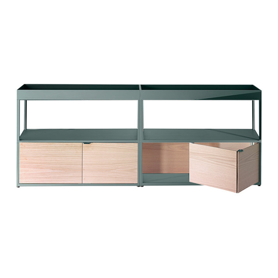
Shelving system
Hide thumbs
Also See for New Order:
- User manual ,
- Instruction manual (78 pages) ,
- Instruction manual (34 pages)
Advertisement
Quick Links
Advertisement

Related Manuals for Hay New Order


Summary of Contents for Hay New Order
- Page 1 I NST RUCTION M A N UA L N E W OR D E R S H E LV I N G S Y S T E M B y S t e f a n D i e z...
- Page 3 Shelving and storing units form the backbone of New Order Workspace Elements. Attached or detached tables in different heights for sitting as well as standing enable an...
- Page 4 C A R E A N D M A I N T ENA NCE CAUTION With a little care you can prolong the life of your • When you move the shelf, make sure to lift it rather furniture. Follow the instructions for the materials of your than pulling or pushing it to avoid damaging the floor specific product to make sure that it stays in the best and mountings.
- Page 5 C A R E A N D M A I N T ENA NCE POWDER COATED ALUMINIUM UNTREATED WOOD • Clean with a clean cloth wrung in water or in a solution • Clean with a clean cloth wrung in water or in a solution of water and a neutral detergent.
- Page 6 PA RTS PROFILE The profiles are used to link the Shelves/Trays together. There are three types of profiles: Single, Double and Corner Profile. Single Double Corner...
- Page 7 SHELF There are three different types of shelves: Top, Middle and Bottom Shelf. Top Shelf Middle Shelf Bottom Shelf...
- Page 8 TRAY There are three different types of trays: Top, Middle and Bottom Tray. Top Tray Middle Tray Bottom Tray...
- Page 9 EXAMPLES SHELF – SHELF – TRAY The New Order System shown below is made from the following elements: 1 x Bottom Shelf L100, 1 x Middle Shelf L100, 1 x Top Tray L100, 2 x Single Profile Sets. DOUBLE – SHELF – SHELF – TRAY...
- Page 10 6 x SHELF The New Order System shown below is made from the following elements: 1 x Bottom Shelf L100, 4 x Middle Shelf L100, 1 x Top Shelf L100, 5 x Single Profile Sets.
- Page 11 DISCLAIMER The assembly instructions are to be used as a guide showing the concept of the system. It will not necessarily be equal to the system you have acquired.
- Page 12 > A LU M I N I U M PA R T S < IDENTIFYING BOTTOM SHELVES/TRAYS The bottom Shelves/Trays have black adjustable nylon feet mounted in each corner. PLACING BOTTOM SHELVES/TRAYS Place the bottom Shelves/Trays in the desired position and formation.
- Page 13 A perfectly leveled base is essential to achieving a satisfying result. LEVELING USING THE FEET If the New Order bottom Shelves/Trays are not level, adjust them by unscrewing the four adjustable feet. They can either be adjusted by unscrewing by hand or with an Allen key.
- Page 14 MOUNT PROFILE DOUBLE PROFILE Mount the Double Profile where two Shelves/Trays need to be connected. CORNER PROFILE SINGLE PROFILE Mount the Corner Profile where three Mount the Single Profile in each outer Shelves/Trays need to be connected. corner of the system.
- Page 15 SET SCREW PLACEMENT When mounting the profiles to the Shelf/Tray make sure that the set screws are pointing towards the middle of the Shelf/Tray.
- Page 16 AVOIDING GAPS Make sure that the profiles are pressed firmly against the Shelf/Tray leaving no gaps. Any gaps can lead to difficulties later on in the assembly process.
- Page 17 MIDDLE SHELVES/TRAYS The New Order System is constructed in a way that requires you to assemble one complete layer at a time. When a layer is finished you can move on to the next. Alternating between profiles and Shelves/Trays until you reach the top.
- Page 18 IDENTIFYING TOP SHELVES/TRAYS The top Shelves/Trays have only a connector on the bottom side and a clean top.
- Page 19 SET SCREW PLACEMENT Each profile contains set screws that lock into the Shelf/Tray in order to stabilize the construction. When you have finished building the New Order System make sure to tighten all set screws.
-
Page 21: N E W O R D E R
> I N S T R U C T I O N M A N U A L < N E W O R D E R PA N E L S B y S T E FA N D I E Z... - Page 22 > PA R TS < PANELS FOR SHELF There are four different types of panels: Side Panel, Back Panel L100, Back Panel L150, Back Panel L200. SIDE PANEL BACK PANEL L100 BACK PANEL L150 BACK PANEL L200...
- Page 23 INSERT THE PANEL CLIPS Mount the clips in the grooves on the top and bottom of the panel. SOFTENING THE PLASTIC The plastic panel clip needs a small wiggle in order for the plastic to soften thereby making it easier to mount the profile and panel.
- Page 24 INSERTING THE PANELS WOODEN PANEL END FIRST PLASTIC PANEL END SECOND Insert the end of the panel made from wood Insert the end of the panel made from plastic into the profile first. into the other profile.
- Page 25 INSERT THE PANEL CLIPS Mount the clips in the grooves on the top and bottom of the panel.
- Page 26 MOUNTING THE PLASTIC SNAP LOCK After the wooden end of the panel is inserted in the profile move the plastic end of the panel to the second profile. SNAPPING INTO PLACE The plastic end of the panel is made to bend thereby snapping into place in the groove in the profile.
- Page 27 SECURE THE PANEL IN PLACE Secure the panel in place with the clips between the panel and profile.
- Page 28 INSERT THE SIDE PANEL Slide the panel from the inside of the shelving system. Insert the wooden end of the panel into the groove in the profile. Make sure that the recess is pointing outwards.
- Page 29 INSERT THE PANEL CLIPS Mount the clips in the grooves on the top and bottom of the panel. SNAPPING INTO PLACE The plastic end of the panel is made to bend thereby snapping into place in the groove in the profile.
- Page 31 > I N S T R U C T I O N M A N U A L < N E W O R D E R S L I D I N G D O O R S B y S T E FA N D I E Z...
- Page 32 > PA R TS < SLIDING DOORS There are two different door setups depending on your New Order dimensions. Systems L100 and L34 use a single Sliding Door, whereas systems L150 and L200 use two Sliding Doors. SLIDING DOOR SLIDING DOOR RIGHT...
- Page 33 INSERT THE DOORS The cut out must be facing upwards when mounting the sliding doors.
- Page 34 MOUNTING SLIDING DOOR The plastic panels snap into the groove in the profile securing the Sliding Door. 90° BOTTOMS UP Begin by inserting the bottom part of the plastic part into the groove in the profile and apply pressure moving upwards.
- Page 35 TOP GLIDER Push the Glider into the groove on the top Shelf/Tray. Rotate it to hang the glider securely from the Shelf/Tray. HANGING THE TOP GLIDER Insert and rotate the Glider in the groove.
- Page 36 BOTTOM GLIDER Push the glider into the groove on the bottom Shelf/Tray. Rotate it to secure the Glider to the Shelf/Tray.
- Page 37 DOOR TO GLIDER Align the end of the door that is not fixed with the shelving system to the Gliders. TOP GLIDER BOTTOM GLIDER Start by pressing the Sliding Door into the top When the top part is secure proceed to the Glider.
- Page 38 MOUNTING THE HANDLE Align the Handle with the holes in the recessed part of the Sliding Door. HANDLE SNAPPING Press the Handle all the way to the bottom of the Sliding Door allowing it to snap into the plastic bracket.
- Page 39 DOUBLE SECURITY Press the pins into the Sliding Doors and allow the plastic bracket on the rear of the Sliding Door to snap to the Handle.
- Page 41 > I N S T R U C T I O N M A N U A L < N E W O R D E R W H E E L S B y S T E FA N D I E Z...
- Page 42 > PA R TS < WHEELS There are two different types of wheels: Wheels with brake and Wheels without brake DISCLAIMER To ensure stability, wheels must only be mounted and used on systems with one level. STANDARD FEET WHEEL WHEEL WITH BRAKE...
- Page 43 UNSCREW FEET Turn the bottom Shelf/Tray over and unscrew the feet from the base. MOUNTING WHEELS Mount the wheels using the supplied wrench.
- Page 44 DIAGONAL MOUNTING Mount identical wheels diagonally to ensure optimal stability. Retighten all wheels three to four weeks after assembly.
- Page 45 > I N S T R U C T I O N M A N U A L < N E W O R D E R WA L L M O U N T I N G B R A C K E T B y S T E FA N D I E Z...
- Page 46 > PA R TS < WALL MOUNTING BRACKETS There are two types of Wall Mounting Brackets: Brackets for Shelves and Brackets for Trays. WALL MOUNTING BRACKETS SHELF WALL MOUNTING BRACKETS TRAY...
- Page 47 LEVELING THE BRACKETS Use a spirit level to make sure the Wall Mounting Brackets are level prior to drilling. MARK HOLES While the Wall Brackets are held in place mark the center of the holes using a pen.
- Page 48 DRILL HOLES Remove the Wall Brackets and proceed to drill the holes using a drill for the supplied dowel and screws. DOWEL AND SCREWS Insert the provided dowel in the drilled holes. Place the Wall Mount Brackets in place and secure them using the supplied screws and a power drill.
- Page 49 UNSCREW FEET Remove feet or wheels before mounting the shelving system to the wall. Turn the bottom Shelf/Tray over and unscrew the feet from the base. MOUNTING THE SHELVING SYSTEM Push the shelving system up against the wall and let it slide down hooking on to the Wall Mounting Brackets both on the top and bottom.
- Page 50 MOUNTING THE SHELVING SYSTEM The grooves in the top and bottom Shelf/Tray will accommodate the Wall Mounting Bracket and secure it in place.
- Page 51 Brackets in extension of each other. PANELS FOR WALL MOUNT When mounting the special panel for the wall mounted New Order it is of great importance that the two cutouts point upwards. Otherwise they will not snap into place and the panel cannot be mounted.
- Page 53 > I N S T R U C T I O N M A N U A L < N E W O R D E R B O O K E N D B y S T E FA N D I E Z...
- Page 54 > PA R TS < BOOKENDS There are five types of Bookends: Shelf Book Divider Left, Shelf Book Display, Shelf Book Divider With Stopper, Shelf Book Divider Right and Tray Book Divider. SHELF BOOK DIVIDER LEFT SHELF BOOK DIVIDER RIGHT SHELF BOOK DIVIDER WITH STOPPER SHELF BOOK DISPLAY TRAY BOOK DIVIDER...
- Page 55 INSERTING THE BOOKEND Start by inserting the Shelf Bookend into the groove in the Shelf. LOWERING INTO PLACE Having inserted the end of the Bookend into the groove, lower it until it rests on the Shelf.
- Page 56 INSERTING THE BOOKEND Start by inserting the Tray Bookend into the groove in the Tray. LOWERING INTO PLACE Having inserted the end of the Bookend into the groove, lower it until it rests on the Tray.
- Page 59 > I N S T R U C T I O N M A N U A L < N E W O R D E R D I S A S S E M B L Y B y S T E FA N D I E Z...
- Page 60 > R E M O V I N G D O O R < UNHOOKING THE GLIDERS Begin by grasping the plastic part connected to the two glider. Close your hand firmly around the plastic hinge just beneath the top glider to snap it out. Repeat with the bottom glider. PULLING OFF THE DOOR Grab the door at the top on both sides of the plastic.
- Page 61 > R E M OV I N G PA N E L < LOCATE PLASTIC PANEL Begin the disassembly of the New Order System by locating the plastic part of the panel. PRESS THE PANEL OUT Apply pressure to the top and bottom part of the panel near the plastic end.
- Page 62 > R E M OV I N G TO P T R AY / S H E L F < UNSCREW SET SCREWS In order to release the Shelves/Trays from the profiles the set screws must be unscrewn. Make sure not to screw the set screws all the way out but leave them inside the profile thread.
- Page 63 > R E M OV I N G P R O F I L E < UNSCREW SET SCREWS In order to release the profiles from the Shelves/Trays the set screws must be unscrewn. Make sure not to screw the set screws all the way out but leave them inside the profile thread.
- Page 66 Havnen 1 8700 Horsens Denmark +45 4282 0282 / hay@hay.dk 09102017...
Need help?
Do you have a question about the New Order and is the answer not in the manual?
Questions and answers