Table of Contents
Advertisement
Quick Links
Advertisement
Table of Contents

Related Manuals for Lika SMRA


Summary of Contents for Lika SMRA
-
Page 1: User's Guide
User's guide SMRA + MRA Bearingless absolute encoder Smart encoders & actuators... - Page 2 Tous droits réservés. This document and information contained herein are the property of Lika Electronic s.r.l. and shall not be reproduced in whole or in part without prior written approval of Lika Electronic s.r.l. Translation, reproduction and total or partial modification (photostat copies, film and microfilm included and any other means) are forbidden without written authorisation of Lika Electronic s.r.l.
-
Page 3: Table Of Contents
General contents User's guide.......................................1 General contents....................................3 Subject Index......................................5 Typographic and iconographic conventions..........................6 Preliminary information..................................7 1 - Safety summary..................................8 Safety............................................8 Electrical safety........................................8 Mechanical safety......................................9 2 - Identification.....................................10 3 - Mounting instructions................................11 3.1 Overall dimensions....................................11 3.2 Magnetic ring......................................11 3.3 Installing the system....................................12 3.3.1 Mounting the magnetic ring..........................12 3.3.2 Mounting the sensor..............................12 3.3.3 Optional mounting tool............................14... - Page 4 Save parameters..............................30 Save parameters and activate Preset......................30 Device ID..................................30 Time-out..................................30 Software version.................................31 Manufacturer ID.................................31 6.5 Application notes.....................................31 6.6 Recommended BiSS input circuit..............................32 7 - Diagnostic LED...................................33 8 - Error and fault diagnostics..............................34 9 - Maintenance....................................35 10 - Troubleshooting..................................36 11 - Default parameters list...............................37...
-
Page 5: Subject Index
Subject Index Preset setting enable............29 Command................30 CRC................25 e seg. Register address..............25 RW..................25 DATA..................26 Device ID................30 Save parameters...............30 Save parameters and activate Preset......30 Serial number..............29 Error (nE)................24 Software version..............31 Manufacturer ID...............31 Time-out................30 Position.................23 Warning (nW)..............24 Preset..................27... -
Page 6: Typographic And Iconographic Conventions
In this guide, to make it easier to understand and read the text the following typographic and iconographic conventions are used: parameters and objects both of Lika device and interface are coloured in ORANGE; • alarms are coloured in RED;... -
Page 7: Preliminary Information
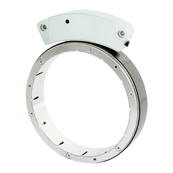
North-South poles generating an absolute pattern. As the ring turns without contact, the sensor detects the rotation and yields the absolute position information through the SSI interface (order code SMRA-BG-... and SMRA-GG-...) or the BiSS C-mode interface (order code SMRA-I7-...). -
Page 8: Safety Summary
• elsewhere in this manual violates safety standards of design, manufacture, and intended use of the equipment; Lika Electronic assumes no liability for the customer's failure to comply • with these requirements. Electrical safety Turn OFF power supply before connecting the device;... -
Page 9: Mechanical Safety
SMRA - SSI and BiSS - minimize noise by connecting the shield and/or the connector housing and/or the sensor to ground. Make sure that ground is not affected by noise. The connection point to ground can be situated both on the device side and on user’s side. -
Page 10: Identification
Information is listed in the delivery document too. Please always quote the order code and the serial number when reaching Lika Electronic for purchasing spare parts or needing assistance. For any information on the technical characteristics of the product refer to the technical datasheet. -
Page 11: Mounting Instructions
SMRA - SSI and BiSS 3 - Mounting instructions WARNING Installation has to be carried out by qualified personnel only, with power supply disconnected and mechanical parts compulsorily in stop. WARNING Install the unit providing protection means against waste, especially swarf as turnings, chips or filings;... -
Page 12: Installing The System
SMRA - SSI and BiSS 3.3 Installing the system Figure 2 3.3.1 Mounting the magnetic ring 1. Mount the magnetic ring 2 on the motor shaft; 2. mount the locking ring 3 and fasten the whole assembly to the motor shaft by using six bolts type M3 x 20 UNI7688. - Page 13 SMRA - SSI and BiSS Figure 3 WARNING Mount the sensor as shown in the Figures. Please mind the direction of the cable outlet. The system cannot operate if mounted otherwise than illustrated in the Figures. WARNING The arrow in Figure 1 is intended to indicate the standard counting direction (count up information when the ring turns in the direction of the arrow).
-
Page 14: Optional Mounting Tool
SMRA - SSI and BiSS 3.3.3 Optional mounting tool To ease the installation of the sensor we suggest using the optional mounting tool. The order code is: TOOL LKM-2386 (for rings Ø 130 mm). MAN SMRA SSI_BiSS E 1.2.odt www.lika.it... -
Page 15: Electrical Connections
SMRA - SSI and BiSS 4 – Electrical connections WARNING Electrical connection has to be carried out by qualified personnel only, with power supply disconnected and mechanical parts compulsorily in stop. WARNING If wires of unused signals come in contact, irreparable damage could be caused to the device. -
Page 16: Connection Of The Shield
SMRA - SSI and BiSS 4.3 Connection of the shield For signals transmission always use shielded cables. The cable shielding must be connected properly to the metal ring nut of the connector in order to ensure a good earthing through the frame of the device. - Page 17 SMRA - SSI and BiSS when the ring turns in reverse of the standard direction, i.e. in the opposite direction to the one shown by the arrow in Figure 1. WARNING After having set the new counting direction it is necessary to set the sensor to zero/preset.
-
Page 18: Ssi Interface
SMRA - SSI and BiSS 5 - SSI interface Order codes: SMRA-BG-… SMRA-GG-… 5.1 SSI (Synchronous Serial Interface) Synchronous Serial SSI (the acronym for Interface) is a synchronous point-to-point serial interface engineered unidirectional data transmission between one Master and one Slave. -
Page 19: Msb Left Aligned Protocol
SMRA - SSI and BiSS transmission. The cycle ends at the last rising edge of the clock signal (3). This means that up to n + 1 rising edges of the clock signals are required for each data word transmission (where n is the bit resolution); for instance, a 13-bit encoder needs 14 clock edges. -
Page 20: Recommended Transmission Rates
SMRA - SSI and BiSS The output code of the sensor can be GRAY or BINARY (see the order code). Structure of the transmitted position value: SMRA-xx-x-06-... … SMRA-xx-x-07-... … SMRA-xx-x-08-... … value … Error bit 5.3 Recommended transmission rates The SSI interface has a frequency of data transmission ranging between 100 kHz and 2 MHz. -
Page 21: Helpful Information
SMRA - SSI and BiSS NOTE For any information on the structure of the position information word, please refer to the section “5.2 MSB left aligned protocol” on page 19. The operating or fault status of the device is shown visually also by the LED installed in the side of the sensor, refer to the section “7 - Diagnostic LED”... -
Page 22: Biss C-Mode Interface
6 - BiSS C-mode interface Order code: SMRA-I7-... Lika encoders are always Slave devices and comply with the “BiSS C-mode interface” and the “Standard encoder profile”. Refer to the official BiSS website for all information not listed in this manual (www.biss-interface.com). -
Page 23: Single Cycle Data Scd
SMRA - SSI and BiSS 6.2 Single Cycle Data SCD SCD structure is different according to the resolution of the SMRA model encoder. 6.2.1 SCD structure SCD data has variable length according to the resolution of the encoder. It consists of the following elements: position value (Position), 1 error bit nE (Error (nE)), 1 warning bit nW (Warning (nW)) and a 6-bit CRC Cyclical Redundancy Checking (CRC). -
Page 24: Error (Ne)
SMRA - SSI and BiSS Error (nE) (1 bit) The error bit nE is intended to communicate the normal or fault status of the Slave. “1”: correct status (the sensor is working properly, there are no active errors) “0”: an error is active: position calculation error, invalid position value;... -
Page 25: Crc
SMRA - SSI and BiSS NOTE For any information on fault conditions and their solution please refer to the sections “8 - Error and fault diagnostics” on page 34 and “10 - Troubleshooting” on page 36. Correct transmission control (inverted output). Cyclical Redundancy Checking is an error checking which is the result of a “Redundancy Checking”... -
Page 26: Data
SMRA - SSI and BiSS DATA When you need to write in a register (RW = “01”), it allows to set the value to be written in the register (transmitted by the Master to the Slave). When you need to read from a register (RW = “10”), it shows the value read in the register (transmitted by the Slave to the Master). -
Page 27: Implemented Registers
SMRA - SSI and BiSS 6.4 Implemented registers Register (hex) Function 12 - 13 Preset Preset setting enable Serial number 60 … 63 Command Device ID 78 … 7B Time-out Software version 7E - 7F Manufacturer ID All registers described in this section are listed as follows:... - Page 28 SMRA - SSI and BiSS After having entered a value next to the Preset registers you can either save it without activating the preset function or both save and activate it at the same time. Use the Save parameters function (set “01” in the Command register) to save the new Preset value without activating it.
-
Page 29: Preset Setting Enable
SMRA - SSI and BiSS 4. To save the new Preset value, you must use the Save parameters function in the Command register (set “01” in the Command register). 5. Otherwise, to both save and activate the the new Preset value at the same time, you must use the Save parameters and activate Preset function in the Command register (set “02”... -
Page 30: Command
SMRA - SSI and BiSS Command [77, wo] Value Function Save parameters Save parameters and activate Preset After having set a new value in any register use the Save parameters function in the Command register to save the new value. Set “01” in the Command register. -
Page 31: Software Version
SMRA - SSI and BiSS Software version [7D, ro] This register contains the software version of the device. Data is expressed in hexadecimal ASCII code. Register ASCII EXAMPLE If the value in the register 7D is “31” hex, then the software version is “1”. -
Page 32: Recommended Biss Input Circuit
SMRA - SSI and BiSS 6.6 Recommended BiSS input circuit MAN SMRA SSI_BiSS E 1.2.odt www.lika.it www.lika.biz... -
Page 33: Diagnostic Led
SMRA - SSI and BiSS 7 - Diagnostic LED One LED is installed in the side of the sensor and is designed to show visually the operating or fault status of the device, as explained in the following table. The operating or fault status of the device is also communicated through the error bit, refer to the section “5.4 Error bit”... -
Page 34: Error And Fault Diagnostics
SMRA - SSI and BiSS 8 - Error and fault diagnostics At power on or during operation the following errors may occur: when switching on the system an alarm is triggered through both the diagnostic LED and the dedicated bit (SSI interface: refer to the section “5.4 Error bit”... -
Page 35: Maintenance
SMRA - SSI and BiSS 9 - Maintenance WARNING Maintenance operations have to be carried out by qualified personnel only, with power supply disconnected and mechanical parts compulsorily in stop. The magnetic measurement system does not need any special maintenance;... -
Page 36: Troubleshooting
A magnetic part has been placed between the sensor and the magnetic surface of the ring. The sensor has been damaged by short circuit or wrong connection (reverse polarity protection is provided for the version SMRA-xx-2-... only). Fault: The measured values are either inaccurate or not provided in the whole circumference of the ring. -
Page 37: Default Parameters List
SMRA - SSI and BiSS 11 - Default parameters list BiSS C-mode interface Parameters list Default value * Preset 00 00 Preset setting enable Time-out * All values are expressed in hexadecimal notation. MAN SMRA SSI_BiSS E 1.2.odt www.lika.it www.lika.biz... - Page 38 This page intentionally left blank...
- Page 39 This page intentionally left blank...
- Page 40 Error bit and LED operation meaning update, new optional mounting tool Dispose separately Lika Electronic Via S. Lorenzo, 25 - 36010 Carrè (VI) - Italy Tel. +39 0445 806600 Fax +39 0445 806699 Italy : eMail info@lika.it - www.lika.it World : eMail info@lika.biz - www.lika.biz...
Need help?
Do you have a question about the SMRA and is the answer not in the manual?
Questions and answers