Table of Contents
Advertisement
Quick Links
Smart encoders & actuators
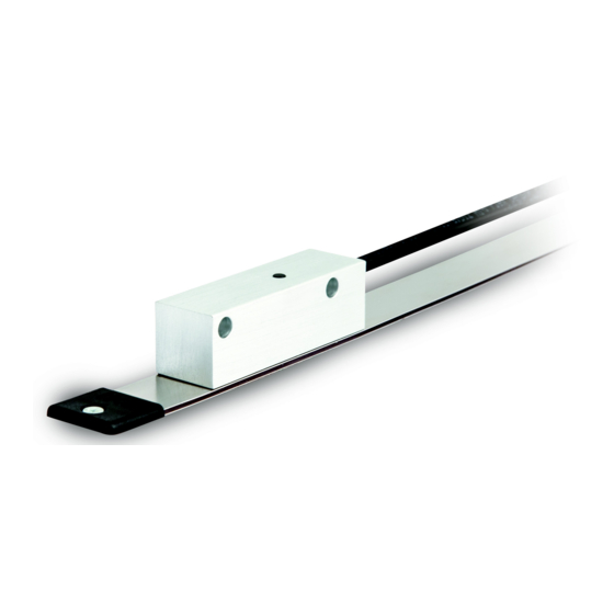
SMA5 +
MTA5
• SMA5 absolute linear encoder
• MTA5 tape, 5 mm pitch, unaffected by dust and liquids
• Max. measuring length 5,100 mm / 200.787"
• Resolution from 100 µm down to 5 µm
• SSI interface
Suitable for the following models:
SMA5 -GA-...
•
Lika Electronic
User's guide
•
Tel. +39 0445 806600
Table of Contents
•
info@lika.biz
11
14
17
18
19
•
www.lika.biz
5
6
7
8
Advertisement
Table of Contents

Subscribe to Our Youtube Channel
Related Manuals for Lika SMA5-GA Series


Summary of Contents for Lika SMA5-GA Series
-
Page 1: Table Of Contents
1 - Safety summary 2 - Identification 3 – Mounting instructions 4 - Electrical connections 5 - SSI interface 6 – Error and fault diagnostics 7 - Maintenance 8 - Troubleshooting Lika Electronic • Tel. +39 0445 806600 • info@lika.biz • www.lika.biz... - Page 2 Tous droits réservés. This document and information contained herein are the property of Lika Electronic s.r.l. and shall not be reproduced in whole or in part without prior written approval of Lika Electronic s.r.l. Translation, reproduction and total or partial modification (photostat copies, film and microfilm included and any other means) are forbidden without written authorisation of Lika Electronic s.r.l.
-
Page 3: General Contents
General contents User's guide......................................1 General contents....................................3 Typographic and iconographic conventions........................4 Preliminary information..................................5 1 - Safety summary............................6 1.1 Safety......................................6 1.2 Electrical safety..................................6 1.3 Mechanical safety..................................7 2 - Identification............................7 3 – Mounting instructions........................... 8 3.1 Overall dimensions................................8 3.2 Magnetic tape..................................8 3.3 Mounting the sensor................................9 4 - Electrical connections........................... -
Page 4: Typographic And Iconographic Conventions
Typographic and iconographic conventions In this guide, to make it easier to understand and read the text the following typographic and iconographic conventions are used: parameters and objects both of the device and the interface are coloured in GREEN; • alarms are coloured in RED;... -
Page 5: Preliminary Information
Preliminary information This guide is designed to provide the most complete and exhaustive information the operator needs to correctly and safely install and operate the SMA5 series absolute linear encoder. SMA5 is designed to measure displacements in industrial machines and automation systems. The measurement system includes a magnetic tape and a magnetic sensor with conversion electronics. -
Page 6: Safety Summary
• elsewhere in this manual violates safety standards of design, manufacture, and intended use of the equipment; Lika Electronic assumes no liability for the customer's failure to comply • with these requirements. 1.2 Electrical safety Turn OFF power supply before connecting the device;... -
Page 7: Identification
Information is listed in the delivery document too. Please always quote the order code and the serial number when reaching Lika Electronic for purchasing spare parts or needing assistance. For any information on the technical characteristics of the product refer to the technical datasheet. -
Page 8: Mounting Instructions
SMA5 3 – Mounting instructions WARNING Installation has to be carried out by qualified personnel only, with power supply disconnected and mechanical parts compulsorily in stop. 3.1 Overall dimensions 3.2 Magnetic tape The sensor has to be paired with the MTA5 type magnetic scale only. For detailed information on the MTA5 type scale and how to mount it refer to the specific technical documentation. -
Page 9: Mounting The Sensor
SMA5 3.3 Mounting the sensor Figure 1 Make sure the mechanical installation complies with the system requirements concerning distance, planarity and parallelism between the sensor and the scale. Avoid contact between the parts. Sensor is fixed by means of two M5 25 mm min. - Page 10 SMA5 Figure 2 WARNING After having installed the sensor on the magnetic scale a zero setting operation is compulsorily required. The zero setting operation is further required every time either the sensor or the scale is replaced. For further information refer to page 12.
-
Page 11: Electrical Connections
4.1 M12 8-pin connector specifications M12 8-pin connector male, frontal side A coding 4.2 M8 cable specifications Model : LIKA HI-FLEX sensor cable type M8 Wires : 2 x 0.22 mm + 6 x 0.14 mm (24/26 AWG) Jacket : Matt Polyurethane (TPU) halogen free, oil, hydrolysis, abrasion resistant : tinned copper braid, coverage ... -
Page 12: Ground Connection
SMA5 4.3 Ground connection Minimize noise by connecting the shield and/or the connector housing and/or the sensor to ground. Make sure that ground is not affected by noise. The connection point to ground can be situated both on the device side and on user’s side. -
Page 13: Features Summary
SMA5 4.6 Features summary Order code Resolution mm SMA5-GA-100-... SMA5-GA-50-... 0.05 SMA5-GA-10-... 0.01 SMA5-GA-5-... 0.005 5,100 mm / 200.787” Max. length of the scale (5,035 mm / 198.23”) (max. measuring length) Pole pitch dimension 5 mm Max. information 20 bits (1,048,575) (max. -
Page 14: Ssi Interface
SMA5 5 - SSI interface Order code: SMA5-GA-… 5.1 SSI (Synchronous Serial Interface) Synchronous Serial SSI (the acronym for Interface) is a synchronous point-to-point serial interface engineered unidirectional data transmission between one Master and one Slave. Developed in the first eighties, it is based on the RS- 422 serial standard. -
Page 15: Lsb Right Aligned Protocol
SMA5 transmission. The cycle ends at the last rising edge of the clock signal (3). This means that up to n + 1 rising edges of the clock signals are required for each data word transmission (where n is the bit resolution); for instance, a 13-bit encoder needs 14 clock edges. -
Page 16: Recommended Transmission Rates
SMA5 WARNING The position value issued by the sensor is expressed in pulses; to convert the pulses into a metric measuring unit you must multiply the number of detected pulses by the resolution. EXAMPLE SMA5-GA-5-… resolution = 5 µm = 0.005 mm detected pulses = 123 position value = 123 * 5 = 615 µm = 0.615 mm 5.3 Recommended transmission rates... -
Page 17: Error And Fault Diagnostics
SMA5 6 – Error and fault diagnostics In case of wrong alignment between the sensor and the magnetic scale, at power on or during operation the following errors may occur: the LED lights up when switching on the system: there is a wrong alignment;... -
Page 18: Maintenance
SMA5 7 - Maintenance The magnetic measurement system does not need any particular maintenance; anyway it has to be handled with the utmost care as any delicate electronic equipment. From time to time we recommend the following operations: periodically check the soundness of the structure and make sure that there are no loose screws;... -
Page 19: Troubleshooting
SMA5 8 - Troubleshooting The following list shows some typical faults that may occur during installation and operation of the magnetic measurement system. Fault The system does not work (no pulse output) The scale and/or the sensor are not installed properly (the active surface of the scale does not match the sensitive part of the sensor). - Page 20 M12 8-pin connector added, installation with cover 13.11.2015 strip 21.04.2016 General review 31.01.2020 SSI information updated, general review Lika Electronic Via S. Lorenzo, 25 • 36010 Carrè (VI) • Italy Tel. +39 0445 806600 Fax +39 0445 806699 info@lika.biz •...
Need help?
Do you have a question about the SMA5-GA Series and is the answer not in the manual?
Questions and answers