Table of Contents
Advertisement
Quick Links
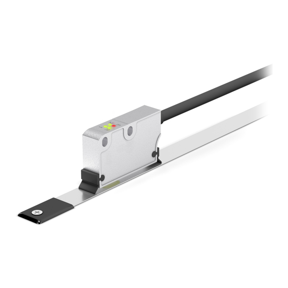
Smart encoders & actuators
SME12
SME22
SME52
• Incremental linear encoder for 1-, 2- & 5-mm pole pitch tapes
• Resolution options between 0.5 µm and 50 µm
• Measuring length up to 100 m / 328 ft
• IP67 protection rate
• Wide mounting tolerances up to 2 mm / 0.078"
• With external limit switches to mark off the travel
Suitable for the following models:
SME12
•
SME22
•
SME52
•
Lika Electronic
User's guide
•
Tel. +39 0445 806600
Table of Contents
•
info@lika.biz
18
29
•
www.lika.biz
6
8
9
Advertisement
Table of Contents

Related Manuals for Lika SME22


Summary of Contents for Lika SME22
-
Page 1: Table Of Contents
User's guide Smart encoders & actuators SME12 SME22 SME52 • Incremental linear encoder for 1-, 2- & 5-mm pole pitch tapes • Resolution options between 0.5 µm and 50 µm • Measuring length up to 100 m / 328 ft •... - Page 2 Tous droits réservés. This document and information contained herein are the property of Lika Electronic s.r.l. and shall not be reproduced in whole or in part without prior written approval of Lika Electronic s.r.l. Translation, reproduction and total or partial modification (photostat copies, film and microfilm included and any other means) are forbidden without written authorisation of Lika Electronic s.r.l.
-
Page 3: General Contents
General contents User's guide......................................1 General contents.....................................3 Typographic and iconographic conventions........................4 Preliminary information................................5 1 Safety summary............................. 6 1.1 Safety.....................................6 1.2 Electrical safety.................................6 1.3 Mechanical safety..............................7 2 Identification............................8 3 Mechanical installation........................9 3.1 Overall dimensions..............................9 3.2 Sensor and scale / ring combination......................10 3.3 Magnetic tape.................................10 3.4 Magnetic rings................................10 3.5 Mounting the sensor with magnetic tape....................11... -
Page 4: Typographic And Iconographic Conventions
Typographic and iconographic conventions In this guide, to make it easier to understand and read the text the following typographic and iconographic conventions are used: parameters are coloured in GREEN; • alarms are coloured in RED; • states are coloured in FUCSIA. •... -
Page 5: Preliminary Information
SME12, SME22 and SME52. SME12, SME22 and SME52 linear encoders are designed to measure linear or angular displacements on industrial machines and automation systems. The measurement system includes a magnetic tape / magnetic ring and a magnetic sensor. -
Page 6: Safety Summary
• elsewhere in this manual violates safety standards of design, manufacture, and intended use of the equipment; Lika Electronic assumes no liability for the customer's failure to comply • with these requirements. 1.2 Electrical safety Turn OFF the power supply before connecting the device;... -
Page 7: Mechanical Safety
SME12 • SME22 • SME52 - minimize noise by connecting the cable shield and the frame to ground. Make sure that ground is not affected by noise. The connection point to ground can be situated both on the device side and on user’s side. The best solution to minimize the interference must be carried out by the user;... -
Page 8: Identification
Information is listed in the delivery document too. Please always quote the order code and the serial number when reaching Lika Electronic for purchasing spare parts or needing assistance. For any information on the technical characteristics of the product refer to the technical catalogue. -
Page 9: Mechanical Installation
SME12 • SME22 • SME52 Mechanical installation WARNING Installation must be carried out by qualified personnel only, with power supply disconnected and mechanical parts compulsorily in stop. 3.1 Overall dimensions (values are expressed in mm) A Reference sensor “R” (page 23) D Optional cleaning wipers (page 17) B Limit switch sensors “LS”... -
Page 10: Sensor And Scale / Ring Combination
SME12 • SME22 • SME52 3.2 Sensor and scale / ring combination The sensor has to be compulsorily paired with its specific type of magnetic scale or ring as indicated in the table below. For any information on the scale or ring please refer to the specific documentation. -
Page 11: Mounting The Sensor With Magnetic Tape
SME12 • SME22 • SME52 3.5 Mounting the sensor with magnetic tape Figure 1 - Encoder / tape mounting gap Make sure that the mechanical installation complies with the system requirements concerning distance, planarity and parallelism between the sensor and the scale as shown in Figure 2. Avoid contact between the parts. - Page 12 SME12 • SME22 • SME52 0.1 mm 1.0 mm 0.1 mm 0.7 mm SME22 0.004” 0.039” 0.004” 0.027” 0.1 mm 2.0 mm 0.1 mm 1.7 mm SME52 0.004” 0.078” 0.004” 0.067” For better operation we suggest the following distance D:...
-
Page 13: Mounting The Sensor With "R" Reference
SME12 • SME22 • SME52 3.6 Mounting the sensor with “R” Reference The Reference signal is available with "R" order code and in combination with LKM-1309/x Reference pole support; “x” is the pole pitch of the tape. It provides a... -
Page 14: Mounting The Sensor With Ls1 And Ls2 Limit Switches
SME12 • SME22 • SME52 0.1 – 0.3 mm 7.3 mm SME12 / LKM-1309/1 0.004” - 0.012” 0.287” 0.5 – 0.7 mm 7.5 mm SME22 / LKM-1309/2 0.020” - 0.027” 0.295” 0.5 – 1.0 mm 7.5 mm SME52 / LKM-1309/5 0.020”... -
Page 15: Measuring Length
SME12 • SME22 • SME52 0.5 – 1.0 mm 7.5 mm SMEx2 - LKM-1309/LS 0.020” - 0.039” 0.295” 3.8 Measuring length The length of the tape can be theoretically unlimited. The tape is supplied in rolls up to 100 m / 328 ft long. - Page 16 SME12 • SME22 • SME52 Figure 5 - Sensor / ring alignment To learn about the mounting tolerances refer to the tables below as well as to Figure 2, Figure 5 and Figure 6. Figure 6 - Sensor / ring mounting gap...
-
Page 17: Standard Counting Direction
SME12 • SME22 • SME52 Recommended distance DR between sensor and MRI Sensor ring 0.25 mm 0.010” SME12 0.50 mm 0.019” SME22 SME52 1.0 mm 0.039” 3.10 Standard counting direction The positive counting direction (the rising edge of A signal leads the rising edge of B signal) is achieved when the sensor moves on the tape according to the arrow shown in Figure 1;... -
Page 18: Electrical Connection
SME12 • SME22 • SME52 Electrical connection WARNING Electrical connection must be carried out by qualified personnel only, with power supply disconnected and mechanical parts compulsorily in stop. WARNING If wires of unused signals come in contact, irreparable damage could be caused to the device. -
Page 19: M10 Cable Specifications
A = A signal; /A = inverted A signal (or complementary signal). All Lika's magnetic sensors can provide AB0, /AB0 output signals. You are advised to always connect the inverted signals if the receiving device will accept them. Otherwise each output should be insulated singularly. -
Page 20: Connection Of The Shield
SME12 • SME22 • SME52 4.3 Connection of the shield For signals transmission always use shielded cables. The cable shielding must be connected properly to the metal ring nut 3 of the connector in order to ensure a good earthing through the frame of the device. To do this disentangle and shorten the shielding 1 and then bend it over the part 2;... -
Page 21: Ab0, /Ab0 Output Channels
SME12 • SME22 • SME52 4.5 AB0, /AB0 output channels Figure 7 - Example with interpolation factor x4 The conversion electronics inside the sensor translates the magnetic fields of the scale / ring into electrical signals equivalent to those of an incremental encoder or similar incremental optical devices. - Page 22 SME12 • SME22 • SME52 If you need to know the interpolation factor, then you have to divide the pole pitch value by the resolution indicated in the order code. EXAMPLE Let's suppose we are using an SME52-xx-x-50-... linear encoder paired with the MT50 magnetic scale;...
-
Page 23: Counting Direction
SME12 • SME22 • SME52 NOTE The standard counting direction (the channel A leads the channel B) is to be intended with sensor moving as shown in Figure 1 in a linear application; with ring turning as indicated by the arrow in Figure 6 in a rotary application. -
Page 24: Ls1 And Ls2 Limit Switches
SME12 • SME22 • SME52 Figure 8 - Reference 4.8 LS1 and LS2 limit switches SMEx2 linear encoders integrate two sensors designed to detect external limit switches (code LKM-1309/LS). They allow to detect the ends in the travel. External references LS1 and LS2 must be installed at either/both ends of the sensor's travel on the side shown in the Figure and according to the indicated tolerances. - Page 25 SME12 • SME22 • SME52 Figure 9 - LS limit switches Outputs of limit switches LS1 and LS2 are open collector type and have Imax = 50 mA. The signal is normally at logic level high (+Vdc) and switches to logic level low (0Vdc) as soon as the external limit switch is detected.
-
Page 26: Diagnostic Leds (Figure 10)
SME12 • SME22 • SME52 4.9 Diagnostic LEDs (Figure 10) Four LEDs located in the upper face of the encoder enclosure are intended to show visually the work status of the device as explained in the following table. Figure 10 - Diagnostic LEDs and optional cleaning wipers... - Page 27 SME12 • SME22 • SME52 tolerances between sensor and tape (or ring) are not met; please refer to the “Mechanical installation” section on page 9. Speed error: overspeed detected, the • sensor exceeded the frequency limit and the zero may be lost; the rotational speed of the ring is too high and the sensor may have lost the zero;...
-
Page 28: Recommended Circuit
SME12 • SME22 • SME52 4.10 Recommended circuit Push-Pull (Y order code) Push-Pull (YC order code) Line Driver (L order code) MAN SME12_SME22_SME52 E 1.6 Electrical connection 28 of 32... -
Page 29: Maintenance And Troubleshooting
SME12 • SME22 • SME52 Maintenance and troubleshooting The magnetic measurement system does not need any particular maintenance; please always consider it is a delicate electronic equipment and therefore it must be handled with care. From time to time we recommend the following... - Page 30 SME12 • SME22 • SME52 A section of the magnetic scale / ring has been damaged mechanically • or magnetically along the measuring length. The measuring error is caused by torsion of the machine structure. • Check parallelism and symmetry of machine movement.
- Page 31 This page intentionally left blank...
- Page 32 Sections “3 – Mechanical installation” and “5 – 11.02.2015 Output signals” revised 16.06.2016 General revision 10.07.2018 New mechanical and electrical version 14.04.2020 LED information updated Lika Electronic Via S. Lorenzo, 25 • 36010 Carrè (VI) • Italy Tel. +39 0445 806600 Fax +39 0445 806699 info@lika.biz •...
Need help?
Do you have a question about the SME22 and is the answer not in the manual?
Questions and answers