Table of Contents
Advertisement
Quick Links
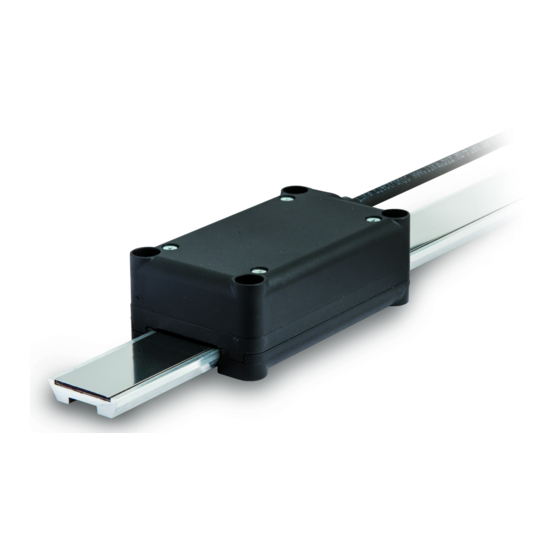
Smart encoders & actuators
SMAG +
MTAG
• SMAG absolute linear encoder
• MTAG guided profile unaffected by dust and liquids
• Measuring length from 115 to 570 mm
• Resolution range from 0.1 mm to 0.005 mm
• SSI interface, LSB Right Aligned protocol
Suitable for the following models:
SMAG -GA-100-...
•
SMAG -GA-50-...
•
SMAG -GA-10-...
•
SMAG -GA-5-...
•
Lika Electronic
User's guide
•
Tel. +39 0445 806600
Table of Contents
Preliminary information
1 – Safety summary
2 - Identification
3 – Mechanical installation
4 – SSI interface
5 - Maintenance
•
info@lika.biz
12
19
•
www.lika.biz
5
6
8
9
Advertisement
Table of Contents

Related Manuals for Lika SMAG-GA-100-...+MTAG-300 Series


Summary of Contents for Lika SMAG-GA-100-...+MTAG-300 Series
-
Page 1: User's Guide
SMAG -GA-100-... • 1 – Safety summary SMAG -GA-50-... • 2 - Identification SMAG -GA-10-... • 3 – Mechanical installation SMAG -GA-5-... • 4 – SSI interface 5 - Maintenance Lika Electronic • Tel. +39 0445 806600 • info@lika.biz • www.lika.biz... - Page 2 Tous droits réservés. This document and information contained herein are the property of Lika Electronic s.r.l. and shall not be reproduced in whole or in part without prior written approval of Lika Electronic s.r.l. Translation, reproduction and total or partial modification (photostat copies, film and microfilm included and any other means) are forbidden without written authorisation of Lika Electronic s.r.l.
-
Page 3: Table Of Contents
Table of contents User's guide................................. 1 Table of contents............................3 Typographic and iconographic conventions....................4 Preliminary information..........................5 1 – Safety summary............................6 1.1 Safety......................................6 1.2 Electrical safety..................................6 1.3 Mechanical safety..................................7 2 - Identification............................8 3 – Mechanical installation.......................... 9 3.1 Overall dimensions (Figure 1)............................9 3.2 Mounting instructions.................................9 3.3 Sensor (Figure 2)..................................10 3.4 Profile of the magnetic tape (Figure 2)........................11... -
Page 4: Typographic And Iconographic Conventions
Typographic and iconographic conventions In this guide, to make it easier to understand and read the text the following typographic and iconographic conventions are used: parameters and objects both of the device and the interface are coloured in GREEN; • alarms are coloured in RED;... -
Page 5: Preliminary Information
Preliminary information This guide is designed to provide the most complete information the operator needs to correctly and safely install and operate the linear encoders with guided profile of the SMAG series that provide SSI interface and Gray output code. The SMAG sensors are engineered to measure linear displacements in industrial machines and automation lines. -
Page 6: Safety Summary
failure to comply with these precautions or with specific warnings elsewhere in this manual violates safety standards of design, manufacture, and intended use of the equipment; Lika Electronic assumes no liability for the customer's failure to comply with these requirements. 1.2 Electrical safety ... -
Page 7: Mechanical Safety
SMAG + MTAG SSI - minimize noise by connecting the shield or the connector housing to ground. Make sure that ground is not affected by noise. The connection point to ground can be situated both on the device side and on user’s side. The best solution to minimize the interference must be carried out by the user;... -
Page 8: Identification
Information is listed in the delivery document too. Please always quote the order code and the serial number when reaching Lika Electronic for purchasing spare parts or needing assistance. For any information on the technical characteristics of the product refer to the technical catalogue. -
Page 9: Mechanical Installation
SMAG + MTAG SSI 3 – Mechanical installation WARNING Installation and maintenance operations must be carried out by qualified personnel only, with power supply disconnected and mechanical parts absolutely in stop. 3.1 Overall dimensions (Figure 1) (values are expressed in mm) Figure 1 L = 195 mm / 7.677”... -
Page 10: Sensor (Figure 2)
SMAG + MTAG SSI 2. or, on the contrary, you can fasten the sensor to a fixed support and move the profile of the magnetic tape. It is customer's duty to evaluate the type of installation that is most suitable for his application. -
Page 11: Profile Of The Magnetic Tape (Figure 2)
SMAG + MTAG SSI 3.4 Profile of the magnetic tape (Figure 2) It is mandatory to pair the sensor with the MTAG type magnetic tape. The profile of the magnetic tape can be secured: 1. to a sliding device driven manually, pneumatically or by a motor; in this first case the tape will move back and forth while the sensor will be mounted in a fixed position;... -
Page 12: Ssi Interface
Counting direction Grey Shielding Shield Case 4.1.1 M8 cable specifications Model : LIKA HI-FLEX sensor cable type M8 Wires : 2 x 0.22 mm + 6 x 0.14 mm (24/26 AWG) Jacket : Matt Polyurethane (TPU) halogen free, oil, hydrolysis, abrasion resistant : tinned copper braid, coverage ... -
Page 13: Connection Of The Shield
SMAG + MTAG SSI 4.1.3 Connection of the shield For signals transmission always use shielded cables. The cable shielding must be connected properly to the metal ring nut of the connector in order to ensure a good earthing through the frame of the device. 4.1.4 Ground connection Minimize noise by connecting the shield or the connector housing to ground. -
Page 14: Counting Direction Input
SMAG + MTAG SSI Max. number of Model Max. value information SMAG-GA-100-... + MTAG-650 5,700 8,192 (13 bits) SMAG-GA-100-... + MTAG-370 2,900 4,096 (12 bits) SMAG-GA-100-... + MTAG-300 2,200 4,096 (12 bits) SMAG-GA-100-... + MTAG-240 1,600 2,048 (11 bits) SMAG-GA-100-... + MTAG-220 1,400 2,048 (11 bits) SMAG-GA-100-... -
Page 15: Ssi (Synchronous Serial Interface)
SMAG + MTAG SSI the Counting direction input to 0Vdc if not used. Connect the counting direction input to 0Vdc to have the count up information when the sensor moves as shown by the white arrow in Figure 2 (or when the profile moves as shown by the black arrow in Figure 2);... -
Page 16: Lsb Right Aligned Protocol
SMAG + MTAG SSI At each change of the clock signal and at each subsequent rising edge (2) one bit is clocked out at a time, up to LSB, so completing the data word transmission. The cycle ends at the last rising edge of the clock signal (3). This means that up to n + 1 rising edges of the clock signals are required for each data word transmission (where n is the bit resolution);... - Page 17 SMAG + MTAG SSI The output code is GRAY. The measuring step is equal to the resolution (0.1 mm … 0.005 mm). Structure of the transmitted position value: SMAG-GA-100-... bits 25 … 14 SMAG-GA-50-... bits 25 … 15 SMAG-GA-10-... bits 25 …...
-
Page 18: Recommended Transmission Rates
SMAG + MTAG SSI 4.4 Recommended transmission rates The SSI interface has a frequency of data transmission ranging between 100 kHz and 1.5 MHz. The CLOCK signals and the DATA signals are transmitted according to the “EIA RS-422” standard. The clock frequency (baud rate) depends on the length of the cables and must comply with the technical information reported in the following table. -
Page 19: Maintenance
SMAG + MTAG SSI 5 - Maintenance This magnetic measurement system does not need any particular maintenance; anyway it has to be handled with the utmost care as it is a delicate electronic equipment. From time to time we recommend the following operations to be performed: periodically check the soundness of the structure and make sure that •... - Page 20 General review, English translation General review, “3 – Mechanical installation” 18.05.2015 section updated General review, Italian and English versions 24.01.2017 separated, mounting instructions updated Lika Electronic Via S. Lorenzo, 25 • 36010 Carrè (VI) • Italy Tel. +39 0445 806600 Fax +39 0445 806699 info@lika.biz...
Need help?
Do you have a question about the SMAG-GA-100-...+MTAG-300 Series and is the answer not in the manual?
Questions and answers