Advertisement
Quick Links
SFAB
Flow sensor
Operating instructions
8156241
2021-05d
[8156243]
Translation of the original instructions
© 2021 all rights reserved to Festo SE & Co. KG
1
About this document
1.1
Applicable Documents
All available documents for the product è www.festo.com/sp.
2
Safety
2.1
General safety instructions
– Only use the product in original status without unauthorised modifications.
– Only use the product if it is in perfect technical condition.
– Observe labelling on the product.
– Condensation, oil mist, foreign matter and other contaminants in the com-
pressed air can damage the product. Only use media in accordance with the
specifications è Technical data.
– This product can generate high frequency malfunctions, which may make it nec-
essary to implement interference suppression measures in residential areas.
2.2
Intended use
The SFAB is designed to monitor changes in the flow rate and air consumption of
gaseous media in piping systems or terminals in industry.
2.3
Training of qualified personnel
Work on the product may only be carried out by qualified personnel who can
evaluate the work and detect dangers. The qualified personnel have skills and
experience in dealing with electropneumatic (open-loop) control technology.
2.4
Range of application and approvals
Certain configurations of the product have been certified by Underwriters Labora-
tories Inc. (UL) for the USA and Canada. These configurations bear the following
mark:
Fig.1
UL Recognized Component Mark for Canada and the United States. Only for
connection to an NEC Class 2 supply. Raccorder Uniquement a un circuit de Classe
2.
Observe the following if the UL requirements are to be complied with in your
application:
• Regulations for complying with the UL certification can be found in the sepa-
rate UL-specific special documentation. The technical data listed there take
priority.
• The technical data in this documentation may show values deviating from this.
3
Additional information
– Contact the regional Festo contact if you have technical problems
è www.festo.com.
– Accessories and spare parts è www.festo.com/catalogue.
4
Product overview
4.1
Festo SE & Co. KG
Ruiter Straße 82
73734 Esslingen
Deutschland
+49 711 347-0
www.festo.com
9
8
7
6
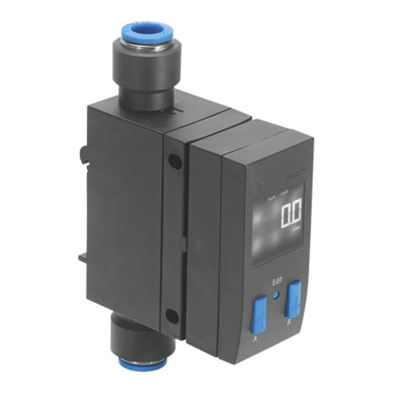
Fig. 2: SFAB
1 Supply port 1
2 Display
3 B pushbutton
4 Edit button
5 A pushbutton
4.2
The SFAB uses a thermal measurement method. Here, the amount of heat drawn
from a heated surface of the sensor by the medium flowing past it is calculated.
Through the amount of heat removed, the flow rate or accumulated air consump-
tion is determined and shown on the display. The connection to higher-level
systems is implemented through 2 binary outputs (Out A/OutB) and one analogue
output. Switching points can be defined for both binary outputs. Switching points
for both binary outputs are possible for flow rate measurement, a consumption
switching pulse for output A (OutA) is possible for cumulative air consumption
measurement. The combination of cumulative air consumption measurement
(OutA) and flow rate measurement (OutB) is possible. The flow value is output
via the analogue output.
5
5.1
1. Maintain lateral distance x = 10 mm to earthed surfaces.
2. Hang SFAB in H-rail.
3. Press SFAB in the direction of the arrow.
5.2
1. Maintain lateral distance x = mm to earthed surfaces.
Product design
Functional principle
Assembly
H-rail (manifold assembly)
Ä SFAB snaps into place.
Wall mounting
1
2
3
4
5
6 Plug for the electrical connection
(M12)
7 Hole for plate mounting
8 Supply port 2
9 Mounting slide for H-rail and wall
mounting (rear)
Advertisement

Related Manuals for Festo SFAB


Summary of Contents for Festo SFAB
- Page 1 Intended use tion is determined and shown on the display. The connection to higher-level The SFAB is designed to monitor changes in the flow rate and air consumption of systems is implemented through 2 binary outputs (Out A/OutB) and one analogue gaseous media in piping systems or terminals in industry.
- Page 2 SFAB-...-2SV 2. Fasten the adapter plate with 2 screws M3. +24 V +24 V 3. Hang the SFAB in the adapter plate. 4. Press SFAB in the direction of the arrow. Ä SFAB snaps into place. Plate mounting PNP/NPN PNP/NPN 1.
- Page 3 To display the settings one by one, press the A/B pushbutton repeatedly. Minimum flow rate (flow low) When all settings have been displayed, the SFAB goes back into RUN mode when Maximum flow rate (flow high) the A pushbutton / B pushbutton are pressed again and displays the current measurement value for the corresponding output.
- Page 4 – Physical units for flow rate [FLW] (l/h, scfm, l/min) Ä SFAB is in RUN mode. – Analogue filter [AnA.F] 14. Check whether the SFAB switches as desired with a test run (vary the flow – Digital filter [dIG.F] rate).
- Page 5 7.7.4.1 Setting standard conditions 2. Press the Edit button to confirm the selection. The air mass flow measured and output by the SFAB refers to standard conditions. Ä [Lock] flashes. The security code can be set. The SFAB is factory calibrated to the physical standard conditions according to 7.7.4.7 Setting the security code...
- Page 6 To reset a measure value to zero, press the B button in RECORDER mode. Operation and use Changes to the device settings take effect immediately at the outputs. The air mass flow displayed by the SFAB refers to the standard condition set in the special menu under Options. When comparing volumetric flow rates: –...
- Page 7 3. For panel mounting: loosen retaining screws. SFAB -10U -50U -200U -600U -1000U For H-rail or wall mounting: loosen the fixing slide è Fig. 9 Electromechanics Electrical connection Straight plug, M12x1, 5-pin Max. connecting cable < 10 length Mechanics Mounting position...
Need help?
Do you have a question about the SFAB and is the answer not in the manual?
Questions and answers