Table of Contents
Advertisement
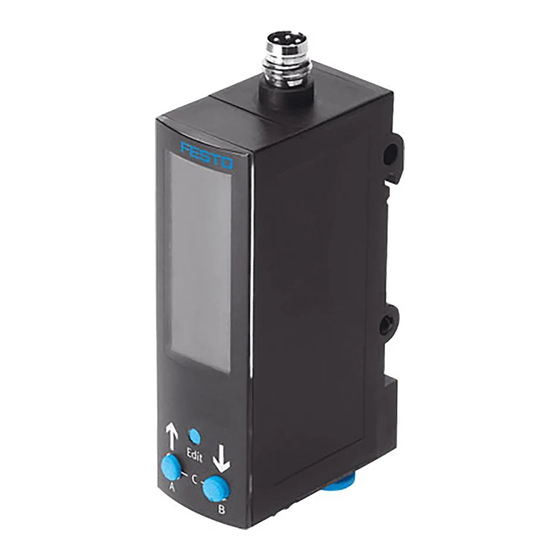
Pressure sensor SDE3
Operating instructions
Original instructions
. . . . . . . . . . . . . . . . . . . . . . . . . . . . . . . . . . . . . . . . . . . . . . . . . . . . . . . . . . . .
For all available product documentation è www.festo.com/pk
1
Operating elements and connections
1
2
aD
aC
aB
aA
aJ
9
1
SDE3 for mounting onto a wall or
H-rail
2
Adapter plate for wall mounting
3
Electrical connection
4
SDE3 for front panel mounting
5
Clamping plate for front panel
mounting
6
Mounting slide (rear)
7
Compressed air or vacuum
connections (only SDE3-...D and
SDE3-...M)
Fig. 1
Key feature
Order
code
Function
SDE3
Pressure measuring range
-V1
-B2
-D2
-D6
-D10
1)
-D12
Supply port
S
D
Z
M
Festo AG & Co. KG
Ruiter Straße 82
73734 Esslingen
Germany
+49 711 347-0
www.festo.com
8078143
2017-09f
[8078145]
4
3
8
7
8
Compressed air or vacuum
connection (only SDE3-...S)
9
Compressed air or vacuum
connections (only SDE3-...Z)
aJ
Label holder
aA
B pushbutton
aB
A pushbutton
aC
Edit button
aD
Display
Type
Pressure sensor
0 ... –1
–1 ... +1
0 ... 2
0 ... 6
0 ... 10
0 ... 12
1x relative pressure
2x relative pressure
1x differential pressure
2x relative pressure, 1x differential pressure analysis
Feature
Display
Mounting/pneumatic
connection
Electrical output
Electrical connection
Electrical accessories
English
1) Key feature only on request
2) Not for SDE3-D12M
3) Not for SDE3-D6M, SDE3-D10M, SDE3-D12M
4) Only in combination with key feature -M8 or -M12
Fig. 2
5
2
Function and application
The SDE3 has been designed for monitoring changes in pressure in the
compressed air system or terminals. Variants for relative pressure measurement
and differential pressure measurement are available:
Type
Description
SDE3-...Z
1x differential pressure
p1 – p2
6
SDE3-...S
1x relative pressure
SDE3-...D
1x relative pressure pA
1x relative pressure pB
SDE3-...M
1x relative pressure pA
1x relative pressure pB
1x differential pressure
analysis pB
SDE3-...V1M
1x differential pressure
analysis pA – pB
1) In A/B: input value for sensor element A/B. In C: calculated
2) Measuring pressure p1 – reference pressure p2
Fig. 3
3
Requirements for product use
Warning
Depending on the functions of the machine/system, the manipulation of signal
statuses can cause serious injury to people or material damage.
• Note that if the switching characteristics of the switching outputs is modified
in EDIT mode, the new status becomes effective immediately.
Enable the password protection option (security code) to prevent accidental
alteration by an unauthorised third party (è Chapter 5.3 section Set security
code).
Warning
The usage of the SDE3 in combination with impermissible media can lead to
personal injury or material damage.
• Use the SDE3 only with compressed air
• Observe the specified air quality class (è Chapter 11 Technical data).
Order
Type
code
-B
Values in bar
-P
Values in psi
2)
-K
Values in kPa
-H
Values in inches of mercury
3)
-W
Values in inches of water
-HQ4
H-rail mounting, push-in connector 4 mm
-WQ4
Wall Mounting, push-in connector 4 mm
-FQ4
Front Panel Mounting, push-in connector 4 mm
-HT532
H-rail mounting, push-in connector 5/32"
-WT532
Wall mounting, push-in connector 5/32"
-FT532
Front panel mounting, push-in connector 5/32"
-2P
2 switching outputs PNP
-2N
2 switching outputs NPN
-M8
Plug connector M8x1
-M12
Plug connector M12, A-coded
-K
Cable 2.5 m
4)
-G
Connecting cable, straight socket, cable length 2.5 m
-W
Connecting cable, angled plug socket, cable length
2.5 m
-G5
Connecting cable, straight socket, cable length 5 m
-W5
Connecting cable, angled plug socket, cable length 5 m
2)
–
pA
Input
Switching
1)
values
outputs
In A
Out A, Out B
In A
Out A, Out B
In A
Out A
In B
Out B
In A
Out A
In B
–
In C
Out B
In C
Out B
Advertisement
Table of Contents

Related Manuals for Festo SDE3 series


Summary of Contents for Festo SDE3 series
- Page 1 ............English 1) Key feature only on request 2) Not for SDE3-D12M For all available product documentation è www.festo.com/pk 3) Not for SDE3-D6M, SDE3-D10M, SDE3-D12M 4) Only in combination with key feature -M8 or -M12 Fig. 2...
- Page 2 – 1) In case of SDE3-…-K and/or the usage of the plug socket with the cable (è www.festo.com/catalogue) 2) Tightening torque for the union nut on plug connector M8: max. 0.3 Nm; on plug connector M12: max. 0.5 Nm.
- Page 3 Special symbols of the segment bars Circuit diagrams Symbols Description SDE3-…-2P-M8-…/SDE3-…-2P-M12-… SDE3-…-2N-M8-…/SDE3-…-2N-M12-… Switching output plug connection Switching output plug connection Marked segments illuminate: – SHOW mode active – Diagnostics: 7-segment display shows error number (e.g. Er01) Marked segments illuminate and [Option] flashes: SDE3-…-2P-K-…...
- Page 4 5.1 RUN mode The following settings and values are indicated in the SHOW mode: In RUN mode, the following are displayed: Settings for Out A/Out B: – The measured values (relative pressure, differential pressure) and – Switching function (threshold value or window comparator) –...
- Page 5 5.3 Edit mode Setting the switching characteristics of the switching outputs Note The process for setting the switch outputs for Out A (A pushbutton) and Out B (B pushbutton) is fundamentally the same. In the following, the process is described using the switching output Out A. The SDE3 is in EDIT mode and [Out A] flashes è...
- Page 6 5.4 TEACH mode Operation The switching points can be learned in TEACH mode. Attention! Note Excessive internal heat will damage the SDE3. The process is the same for teaching the switching outputs Out A (A button) and • Avoid high cycle rates with large pressure amplitudes. Out B (B button).
- Page 7 –12.0 … system) end value 1.000 2.00 2.00 6.00 10.00 12.0 SDE3 defective Send SDE3 to Festo (Differential pressure Incomplete display Display defective Send SDE3 to Festo SDE3-...M) Incorrect measured Only for SDE3-...D, SDE3-...M, Connect tubing of SDE3 correctly Display range...
- Page 8 Appendix Adapter plate hole patterns Fig. 24...
Need help?
Do you have a question about the SDE3 series and is the answer not in the manual?
Questions and answers