Table of Contents
Advertisement
Quick Links
Flow sensor SFAM−62
Operating instructions
Original: de
Note
Installation and commissioning may only be performed in accordance with these
instructions by technicians with appropriate qualifications.
Note
The product is suitable for use only for industrial purposes.
In residential areas, measures for radio interference suppression may be
necessary. It is not suitable for commercial invoicing, such as for measurement
of air consumption in public utilities.
1
Product description
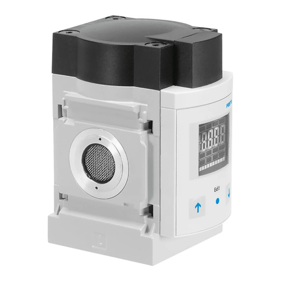
1.1 Overview
SFAM− −M
SFAM− −T
1
Display
2
B button
3
Edit button
4
A button
5
Plug for electrical connection
Fig. 1
Festo AG & Co. KG
Postfach
D−73726 Esslingen
++49/711/347−0
www.festo.com
743 859
0902NH
6
Supply port
7
Sieve cartridge
8
Starting stretch
1.2 Features
Feature
Basic type
Grid dimension
Flow measuring range
g
g
Flow input
p
Type of fastening
yp
g
Electrical output
p
1)
Electrical accessories
1) Included in the scope of delivery.
Fig. 2
2
Function and application
The SFAM is designed to monitor changes in flow and air consumption for suitable
media in pipe systems or end devices in industry; suitable media è chapter 11
Technical Specifications. The structural design enables autonomous operation
(SFAM− −T) or combination with service units of the MS series (SFAM− −M).
Measurement is carried out by means of a thermal procedure. The amount of heat,
which is drawn from a heated surface of the sensor by the medium flowing through
it, is calculated here. Through the amount of heat removed, the flow or accumu
lated air consumption is determined and shown on the display. The connection to
higher−level systems is made via 2 binary outputs (Out A/B) and one analogue
output (Out C). Switching points can be set for both binary outputs. For flow
measurement, switching points are possible for both binary outputs, and for accu
mulated air consumption measurement a consumption switch impulse for output A
(Out A). The combination of accumulated air consumption measurement (Out A)
and flow measurement (Out B) is possible. The flow rate value is passed on via the
analogue output.
3
Conditions for the safe use of the product
1
Warning
2
Depending on the functioning of the machine/system, manipulation of signal
3
states may cause serious personal injury.
4
· Note that if the switching status of the outputs is modified in Edit mode, the
5
new status will be effective immediately.
6
· Activate the password protection (security code) in order to prevent the
7
unintentional change by unauthorized third parties è chapter 5.4, section
Security code.
Warning
Use of the product in combination with prohibited media can result in personal
injury.
· Do not use the product in conjunction with inflammable gases, corrosive
gases, oxygen etc. The product is intended only for measuring the flow of
media, which are listed as suitable in the specifications chapter 11.
5
Important
8
Condensation water, oil mist, foreign matter and other dirt in the compressed air
6
can damage the product and cause incorrect measurements and functional
disorders.
· Make sure that the specified air quality class is maintained for the operating
medium è chapter 11 Technical specifications.
Note
Improper handling can result in malfunctions.
· Make sure that the following specifications are always observed:
Order
Design
code
SFAM
Flow sensor
−62
62 mm
−1000
max. 1000 l/min
−3000
max. 3000 l/min
−5000
max. 5000 l/min
L
unidirectional from the left
R
unidirectional from the right
−M
manifold assembly
−T
thread fitting
−W
additional wall mounting
G12
G½
½" NPT
N12
−2SA
2x PNP or NPN, 1 analogue output 4
−2SV
2x PNP or NPN, 1 analogue output 0
−M12
plug M12x1, 5−pin, A−coded
−2.5S
connecting cable, straight socket, cable length 2.5 m
−5S
connecting cable, straight socket, cable length 5 m
−2.5A
connecting cable, angled socket, cable length 2.5 m
−5A
connecting cable, angled socket, cable length 5 m
20 mA
10 V
Advertisement
Table of Contents

Related Manuals for Festo SFAM-62


Summary of Contents for Festo SFAM-62
- Page 1 Grid dimension −62 62 mm Flow measuring range −1000 max. 1000 l/min −3000 max. 3000 l/min Festo AG & Co. KG −5000 max. 5000 l/min Flow input unidirectional from the left Postfach unidirectional from the right D−73726 Esslingen Type of fastening −M...
- Page 2 4.3 Electrical connection · Compare the maximum values specified in these operating instructions with your actual application (e.g. operating media, pressures, forces, torques, temperatures, masses, speeds, operating voltages, flow rates). Warning · Take into consideration the ambient conditions at the location of use. Use only power units which guarantee reliable electrical isolation of the ·...
- Page 3 Preparing commissioning Consumption switch impulse [CI] with accumulated air consumption In the base state, the product is in the RUN mode. The current measurement value measurement is displayed. The base state can be reached from other modes by: Setting NO (normally open closer) Setting NC (normally closed opener) pressing Edit button for 3 seconds or passage of a monitoring time, timeout.
- Page 4 The following settings are displayed for OUT A: With flow measurement [FLW]: the switching function (threshold value or window comparator) switching point [SP], switching points [SP.Lo] and [SP.Hi] hysteresis [Hy] switching element function [no/nc] (closer/opener) minimum flow value [F.Lo] (Flow Low) In order to delete the minimum value, press the EDIT button briefly.
- Page 5 The EDIT mode enables the following settings: b) Setting switching function for air consumption measurement switching mode for Out A (air consumption [ConS] or flow [FLW] ) The SFAM is in EDIT mode and [Out A] is flashing, switching function (threshold−value or window comparator for Out A and Out B) start è...
- Page 6 a) Setting standard conditions e) Setting the physical unit for the flow The air mass flow measured and output by the SFAM refers to standard conditions. 11. Select the desired setting (m , scfm or l) with the A/B buttons. The SFAM is calibrated at the factory to the physical standard conditions in 12.
- Page 7 · Press the B button in the RECORDER mode to reset a measurement value to zero. Accessories Select the appropriate accessories from our catalogue. è www.festo.com/catalogue/SFAM Operation Important Excessive internal heat will destroy the SFAM. · Avoid high cycle frequencies with large pressure amplitudes. Otherwise, the admissible limit temperatures of the used materials will be exceeded.
- Page 8 Technical specifications SFAM −1000 −3000 −5000 SFAM −1000 −3000 −5000 −M −T −M −T −M −T −M −T −M −T −M −T General information Mechanics Certification C tick Mounting position Horizontal ±5 CE symbol (è Conformity declaration) In accordance with EU EMC directive Pneumatic connection G1/2 G1/2...
Need help?
Do you have a question about the SFAM-62 and is the answer not in the manual?
Questions and answers