Table of Contents
Advertisement
Advertisement
Table of Contents

Subscribe to Our Youtube Channel
Related Manuals for Festo SFAH


Summary of Contents for Festo SFAH
- Page 1 Flow sensor SFAH Description Platzhalter 8075046 2017-09 [8075048]...
- Page 2 Identification of hazards and instructions on how to prevent them: Warning Hazards that can cause death or serious injuries Note Dangers that can result in material damage or failure of function. Other symbols: Recommendations or references to additional sources of information. Festo – SFAH –...
-
Page 3: Table Of Contents
SFAH English – Flow sensor SFAH Table of contents About this document ............ - Page 4 Block parameterisation for analog output ......Festo – SFAH – English...
- Page 5 Example for calculating the maximum display error ......Festo – SFAH – English...
-
Page 6: About This Document
This document describes the use of the above-mentioned product. Certain aspects of use are described in other documents and must be observed (è 1.1 Further applicable documents). Further applicable documents For all available product documentation è www.festo.com/pk Device description file (IODD) è www.festo.com/sp Festo – SFAH – English... -
Page 7: Safety
SFAH Safety Intended use The SFAH is intended for monitoring the flow of gaseous media in piping systems or terminals in the in dustrial sector è Chapter 13 Technical data. General safety information • Note that if the switching status of the outputs is modified in the Edit mode, the new status will be effective immediately. -
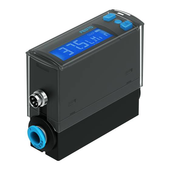
Page 8: Product Overview
SFAH Product overview Configuration A-key Flow connection è Marking on the product Edit button Plug for electrical connection B-key Display Flow connection è Marking on the product Fig. 1 Festo – SFAH – English... -
Page 9: Product Variants And Type Code
Test report Tab. 1 Function The SFAH measures the flow rate (standard flow rate, mass flow rate) with the help of a thermal pro cedure. Measurements are carried out using a micromechanical sensor element with a downstream electronic evaluation unit. -
Page 10: Operating Statuses
Setting of parameters TEACH mode – Acceptance of the current measured value to determine switching points Tab. 2 Operating statuses of the SFAH Switching outputs 6.2.1 Switching functions Threshold value comparator in the flow measurement for OutA or OutB _|¯... - Page 11 TP1 = SP.Lo, TP2 = SP.Hi TP1=SP.Lo TP2=SP.Hi TP1=SP.Lo TP2=SP.Hi 1) SP.Lo = smaller value, SP.Hi = larger value, independent of the Teach sequence Tab. 4 Window comparator: setting of switching points [SP.Lo] and [SP.Hi] and hysteresis [HY] Festo – SFAH – English...
- Page 12 TEACH mode – 2 Teach points (TP1, TP2) – TP1 = SP.Lo, TP2 = SP.Hi 1) SP.Lo = smaller signal value, SP.Hi = larger signal value, independent of the Teach sequence Tab. 6 Festo – SFAH – English...
-
Page 13: Change In Colour
(è Fig. 2) for an adjustable period of time. With each switching impulse, the volume/load measure ment is started again (è Fig. 3). Volume/load pulse with accumulated volume measurement Setting NO (normally open) Setting NC (normally closed) Pulse Pulse Fig. 3 Festo – SFAH – English... -
Page 14: Analogue Output
-80 % Analogue signal Scaled Not scaled Starting point of the scaled sensing range (In.Lo) End point of the scaled sensing range (In.Hi) Fig. 4 Example: scaling of the analogue signal at the current output Festo – SFAH – English... -
Page 15: Filters
Air pressure (absolute) [bar] / 1.01325 / 1.01325 / [kPa] 101.325 101.325 Temperature [°C] Air humidity Status information “Option” Does not light up Lights up Lights up Correction factor, measurement range 1.055 1.087 limit value Fig. 6 Festo – SFAH – English... -
Page 16: Replicating Parameters
SFAH Calibration of the SFAH refers back to the physical standard conditions in accordance with DIN 1343. If a standard other than DIN 1343 is selected, the specified measurement range (±100 % FS) changes in value by the factor specified in Fig. 6. This change is visualised in the display through [Option]. -
Page 17: Installation
Any mounting position is possible but can have an influence on measurement precision (è Chapter 13, Nominal conditions). 7.1.1 Plate mounting • Secure the SFAH to the plate by using screws of suitable length. – Tightening torque: 0.5 Nm – Hole diameter: max 3.3 mm Fig. -
Page 18: Wall Mounting
Fig. 10 7.1.5 Front panel mounting kit 1. Mount H-rail mounting on the SFAH. – Tightening torque 0.5 Nm 2. Mount accompanying hexagon head screw on the H-rail mounting. 3. Push panel frame through cut-out (62 mm x 24 mm _ 0.1 mm). -
Page 19: Pneumatic Installation
For the bidirectional sensors SFAH-…B-…, the flow can be supplied at connection 1 or connection 2. To have a sign that correctly represents the flow direction in the display, the flow direction can be set in the Edit menu and also represented in the sub-display. -
Page 20: Electrical Installation
Brown (BN) Operating voltage +24 V DC White (WH) Switching output OutB or analogue output Blue (BU) Black (BK) Switching output OutA, volume/load pulse or IO-Link (C/Q line) Colours apply for connecting cables NEBU-...M8... Fig. 13 Festo – SFAH – English... -
Page 21: Commissioning
Upper output display: In the RUN mode, which signal is allocated to pin 4 (M8) or pin 2 (L1) is displayed. Lower output display: In the RUN mode, which signal is allocated to pin 2 (M8) or pin 3 (L1) is displayed. Festo – SFAH – English... - Page 22 Additional settings (pulse at the output) [100] [PULS] Duration of the volume or load pulse at the output Analogue output [Edit] [ANLG] Edit menu for the analogue output [0...10] [Out] / [V] Output function of the analogue output Festo – SFAH – English...
-
Page 23: Switch On Sensor (Run Mode)
[bin] / [Out] Shift of the switching outputs (binary) between PNP and NPN [Flow] [bin] / [Pin4] Shift of binary switching output or pulse output. Pin 4 for SFAH-...-M8, pin 2 for SFAH-...-L1 [bin] [FLOW] / [Pin2] Shift of binary switching output or analogue output to pin 2 for SFAH-...-M8, pin 3 for SFAH-...-L1... -
Page 24: Displaying Parameters (Show Mode)
è The first parameter set is displayed. [Fctn] flashes with OutB or [Out] with Anlg (è Fig. 15). The following parameters are displayed by repeatedly pressing the B-key (è Fig. 15). è For bidirectional product variant SFAH-...-B, the flow direction [Path] is displayed at the end. Festo – SFAH – English... - Page 25 Measured value indicator (RUN mode) Edit button A or B key Double-click the A or B key 1) Not for flow unit G.Min 3) Selectable values: 256, 512, 1024 ms 2) Only for bidirectional product variant Fig. 15 Festo – SFAH – English...
-
Page 26: Enter The Security Code (Edit Mode)
1. Press the Edit button briefly. è [Edit] appears. [OutA] flashes. 2. With A or B key, select special menu [Spec]. è [Spec] flashes. 3. Press the Edit button briefly. è [Filt] / [MSEC] flashes. Festo – SFAH – English... -
Page 27: Set Volume Pulse Output (Edit Mode)
– The master sensor is connected to the device sensor and power supply (è Fig. 16). – Parameterisation of the device sensor must not be blocked via IO-Link. – The device sensor is in an unswitched status (switching output PNP, display OutA off ). Festo – SFAH – English... -
Page 28: Configure Sensor (Edit Mode)
Power supply Master sensor Device sensor Fig. 16 Example of port assignment SFAH-...M8 1. Select special menu [Spec] at the master sensor via device settings. 2. Press the Edit button briefly until [MASt] appears. 3. With A or B key, select [ON]. -
Page 29: Zero Point Synchronisation (Zero Adjust)
8.13 Zero point synchronisation (zero adjust) Note Ensure that operating pressure is applied to the SFAH but there is no flow, so that the offset syn chronisation is without error. Prerequisite: – The sensor is ready for operation (RUN mode). -
Page 30: Menu Structure (Edit Mode)
5) Factory setting OFF for unidirectional variant; factory setting ON Bold = factory setting for bidirectional variant 6) For M8 plug: Pin4; for L1 plug: Pin2 7) For M8 plug: Pin2; for L1 plug: Pin3 Festo – SFAH – English... - Page 31 5, 10, 20, 40, 80, 160, 320, 640 s PNP, NPN FLOW, PinX / bin VOL/MASS PinY / FLOW bin, ANLG Code / Lock OFF, 1…9999 MASt OFF, ON Measured value indicator (RUN mode) Fig. 17 Festo – SFAH – English...
-
Page 32: Io-Link Interface Description
SFAH IO-Link interface description Note Related device description file (IODD) è www.festo.com/sp For detailed information on the IO-Link specification and for the Smart Sensor Profil è www.io-link.com General IO-Link specification Characteristic Specification Protocol version Device V1.1 Profile Smart sensor profile... -
Page 33: Identification Parameters
1) Authorisation group: U = user, M = maintenance, S = specialist; Access: R = read, R/W = read and write 2) Value to be defined by user, which is not changed by the “Restore factory settings” command Tab. 13 Identification parameters Festo – SFAH – English... -
Page 34: Io-Link Standard Parameters And Commands
Pause volume / mass recorder in RECORDER mode 1) Authorisation group: U = user, M = maintenance, S = specialist; Access: W = write, – = no access Tab. 15 Additional IO-Link standard parameters and commands Festo – SFAH – English... - Page 35 Teach Flag TP1 for 0x003B Teach State UInteger4 1) Authorisation group: U = user, M = maintenance, S = specialist; Access: R = read, R/W = read and write, – = no access Festo – SFAH – English...
-
Page 36: Smart Sensor Profile Parameters
Not used UInteger16 1) Authorisation group: U = user, M = maintenance, S = specialist; Access: R = read, R/W = read and write, – = no access Tab. 16 Smart Sensor Profile parameters Festo – SFAH – English... -
Page 37: Device-Specific Parameters
(factory setting) colour 1: Red if Out = 0 2: Red if Out = 1 0x0130 OutB, Auto Limit value for 16 … 328, difference a constant input Factory setting monitoring, signal max. signal delta (s.obS) Festo – SFAH – English... - Page 38 0x016C Analog output Analog output 0: 0..10 V type (Out) type voltage output (factory setting) 1: 1..5 V voltage output 2: 4..20 mA current output Festo – SFAH – English...
- Page 39 (Z.Adj) the zero point 1 = on, factory synchronisation setting operation 0x01DD Local display flow Flow at the local 1: OutA flow value (InA) sensor display (factory setting) 2: Volume / mass impulse Festo – SFAH – English...
- Page 40 0 Off (factory block: Off or setting) safety code 1...9999 Code 0x01F0 Normative Reference 0 = 0 reference (REF condition for 1 = 15 Cond) volume flow at 2 = 20 the sensor display (°C) Festo – SFAH – English...
- Page 41 2) For bidirectional variants only 3) For unidirectional variants only 4) Standard value for SFAH-0.1... and SFAH-0.5... 5) Not selectable for SFAH-50..., SFAH-100... and SFAH-200... variants 6) Not selectable for SFAH-0.1..., SFAH-0.5... and SFAH-1... variants 7) Pin 2 for SFAH-...-M8; pin 3 for SFAH-...-L1 8) Pin 4 for SFAH-...-M8;...
- Page 42 Teach-In procedure will end. The “Teach apply” command 0x40 is not used during the Teach-In process. All Teach-In commands are in the format UInterger8. They must be sent with the index 0x0002 (system command) sub-index 0. Festo – SFAH – English...
-
Page 43: Io-Link Teach-In
A corresponding error message is displayed. In this case, restoring the factory settings is recommended. With the factory settings, a free choice of a switching function is always possible. Tab. 18 Teach-In commands Festo – SFAH – English... - Page 44 Block of OutB coherent parameters 9.8.3 Block parameterisation for BDC3 (pulse) Index Sub-Index Name Description 0x4000 Setpoint SP1 Threshold value SP1 0x0149 Pulse impulse length Puls impulse length Tab. 21 Block of coherent Pulse parameters Festo – SFAH – English...
-
Page 45: Block Parameterisation
14 bit PDV measured value (InA) Index 0x0028 Sub-Index Data type UInteger14 Process data Not used BDC3 BDC2 BDC1 Data content Pulse OutB OutA Index 0x0028 Sub-Index Data type Boolean Tab. 23 Mapping the IN process data Festo – SFAH – English... -
Page 46: Block Parameterisation For Analog Output
0.000862227919 0.051733675151 0.031566868095 200 12000 7.06294000 423.7764 258.58 1) Gradient, O = offset Tab. 24 Conversion factors for process data variable, process data variable min, process data vari able max, and setpoint values SP1, SP2 Festo – SFAH – English... -
Page 47: Conversion Factors
0.000021555698 0.000789171702 Offset 50... 50 Gradient 0.003051944088 0.00010777849 0.003945858512 Offset 100 ... 100 Gradient 0.006103888177 0.00021555698 0.007891717024 Offset 200 … 200 Gradient 0.012207776354 0.00043111396 0.015783434047 Offset Tab. 26 Conversion factors for volume / mass units Festo – SFAH – English... -
Page 48: Scaling Factors For Standards
Sub-display: output Er21 / SHRt OutA/Puls 0x1816 Error Event appears Outside Main display: Overload or Eliminate short (disappears) the specification measurement short circuit at circuit value the switching Sub-display: output OutB Er22 / SHRt Festo – SFAH – English... - Page 49 Replace sensor (disappears) Er01 hardware fault Sub-display: FAIL 0x5111 Warning Event appears Outside Main display: Power supply Check power (disappears) the specification measurement too low supply value Sub-display: Er17 / SUPL Tab. 29 IO-Link events Festo – SFAH – English...
-
Page 50: Operation
SFAH Operation After the supply voltage is switched on, the SFAH needs a warm-up time of 10 minutes until it achieves the specified accuracy. The flow rate displayed by the SFAH refers to the standard conditions that were set under Options in the special menu. -
Page 51: Fault Clearance
(same device ID) [Err] / [COM] IO-Link communication error • Check settings of the device sensor • Check line 1) Display flashes red 2) Display illuminates red Tab. 30 Festo – SFAH – English... -
Page 52: Technical Data
[l/min.] 0.002 0.01 0.02 End value [l/min.] Flow measuring range -0.1B- -0.5B- -1B- -5B- -10B- -50B- -100B- -200B- bidirectional, additional Start value [l/min.] -0.002 -0.01 -0.02 -0.1 -0.2 -0.1 -0.5 -100 -200 End value [l/min.] Festo – SFAH – English... - Page 53 0…10 or 1…5 for voltage Output characteristic curve [mA] 4…20 for current Rise time [ms] Max. 3 with FILT = OFF Max. load resistance of cur [Ω] rent output Min. load resistance [kΩ] Voltage output Festo – SFAH – English...
- Page 54 Approx. 90 Information on housing ma Reinforced polyamide terials Materials in contact with medium – NBR – PA reinforced – High-alloy stainless steel – Wrought aluminium alloy, anodised – Silicon – Silicon nitride – Epoxide Festo – SFAH – English...
- Page 55 Pressure drop with 0 bar at [mbar] <5 the output and q max. Pressure drop with 0 MPa at [kPa] <5 the output and q max. Standard nominal flow rate [l/min.] (6 -> 5 bar / 0.6 -> 0.5 MPa) Festo – SFAH – English...
- Page 56 The display error with deviating nominal conditions results from adding all of the error values (range, zero point, temperature, pressure and mounting position). The actual flow rate is in the range of 35 ± (0.7 + 0.5 + 0.89 + 0.35 + 1.5) l/min = 35 ± 3.94 l/min. Festo – SFAH – English...
- Page 57 Copyright: Festo AG & Co. KG Ruiter Straße 82 73734 Esslingen Germany Phone: +49 711 347-0 Fax: +49 711 347-2144 Reproduction, distribution or sale of this document or communica E-mail: tion of its contents to others without express authorization is service_international@festo.com...
Need help?
Do you have a question about the SFAH and is the answer not in the manual?
Questions and answers