Table of Contents
Advertisement
Quick Links
Advertisement
Table of Contents

Related Manuals for Festo SFAB-PNLK Series


Summary of Contents for Festo SFAB-PNLK Series
- Page 1 SFAB-...-PNLK Flow sensor Operating instruc- tion 8172190 2022-08 [8172192]...
- Page 2 Translation of the original instructions IO-Link is a registered trademark of its respective trademark holder in certain countries. ®...
-
Page 3: Table Of Contents
Measuring volume manually in RECORDER mode ....... 24 Festo — SFAB-...-PNLK — 2022-08... - Page 4 Technical data..............44 13.1 Examples for calculating the maximum error of the display ..... . . 48 Festo — SFAB-...-PNLK — 2022-08...
-
Page 5: Applicable Documents
The qualified personnel have skills and experience in dealing with electropneumatic (open-loop) control technology. Additional information – Contact the regional Festo contact if you have technical problems è www.festo.com. – Accessories è www.festo.com/catalogue. Festo — SFAB-...-PNLK — 2022-08... -
Page 6: Product Overview
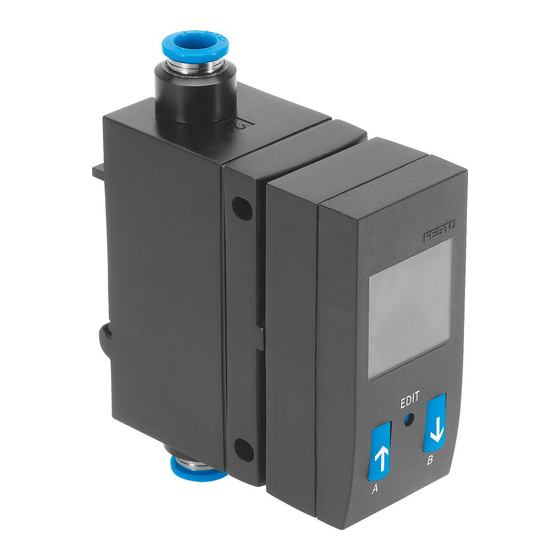
[Edit] key Pushbutton [A] Plug for the electrical connection M12 Pneumatic connection 2 Mounting slide for H-rail mounting and wall mounting, on the back Hole for panel mounting Fig. 1: Control elements and connection elements Festo — SFAB-...-PNLK — 2022-08... -
Page 7: Display Components
Switching output OutB set. ‘Pulse’ Volume pulse selected. ‘Anlg’ Analogue output selected. Information/input display Graphic display of flow measurement Graphic display of volume measurement ‘q’ Input signal flow rate selected. ‘t’ Input signal temperature selected. Festo — SFAB-...-PNLK — 2022-08... - Page 8 Width of the volume pulse or mass pulse Menu for the analogue output ‘1_5V’ ‘Out’ Analogue output type ‘0_10V’, ‘1_5V’, ‘4_20MA’ ‘38’ ‘In.Hi’/‘%’ Scaling of the analogue output: end value ‘3’ ‘In.Lo’/‘%’ Scaling of the analogue output: start value Festo — SFAB-...-PNLK — 2022-08...
-
Page 9: Function
The sensor determines the flow rate or the accumulated volume from the amount of heat removed and shows this on the display. The sensor calculates the temperature of the medium from the sensor signals. The sensor is connected to higher-level Festo — SFAB-...-PNLK — 2022-08... -
Page 10: Operating Statuses
– Setting or modification of parameters. EDIT mode – Acceptance of the current measured value to specify switching points. TEACH mode – Manual measurement of the accumulated volume. RECORDER mode Tab. 3: Operating statuses SFAB Festo — SFAB-...-PNLK — 2022-08... -
Page 11: Switching Outputs
TEACH mode: – 2 teach points (TP1, TP2) – TP1 = SP.Lo, TP2 = SP.Hi 1) SP.Lo = smaller value, SP.Hi = larger value, independent of the teach sequence Tab. 6: 2-point threshold value comparator Festo — SFAB-...-PNLK — 2022-08... -
Page 12: Filter
The filter time equals the time constant Т of a low-pass filter. flow rate signal filter display-filter flow rate display value measuring signal [Filt] [AVER] switching output analogue output switching signal (IO-Link) analogue signal (IO-Link) volume / mass measurement Fig. 4: Effect of filter settings Festo — SFAB-...-PNLK — 2022-08... -
Page 13: Analogue Output
The minimum and maximum values are reset when the operating voltage is switched off. 4.2.8 Replication of the parameters This function enables all settings that have been carried out on one sensor (master) to be transferred to other identical sensors (device). Festo — SFAB-...-PNLK — 2022-08... -
Page 14: Switchover Of Standard Condition
The offset error is visible on the display and can be set to zero using a zero-adjust teach process. Mounting When selecting the mounting position, make sure that no condensation water can accumulate in the sensor. Festo — SFAB-...-PNLK — 2022-08... -
Page 15: Mounting The Sensor On The H-Rail
Fig. 7: Wall mounting 1. Fasten the adapter plate with 2 screws M3. 2. Attach the sensor to the adapter plate. 3. Press the sensor in the direction of the arrow. Ä The sensor snaps into place. Festo — SFAB-...-PNLK — 2022-08... -
Page 16: Mounting The Sensor On The Plate
The flow rate is supplied at connection 1 and withdrawn at connection 2. The direction of flow is indicated on the sensor by an arrow. If the hoses are installed incorrectly, the negative measured values will flash on the display. Festo — SFAB-...-PNLK — 2022-08... -
Page 17: Installation, Electrical
The sensor is in the basic status in RUN mode. The sensor shows the current measured values. The basic status can be reached as follows from other modes: – Press and hold the [Edit] key for 3 seconds. – Expiration of monitoring time (timeout). Festo — SFAB-...-PNLK — 2022-08... -
Page 18: Displaying Parameters In Show Mode
Switching output OutB or analogue output Anlg 1. Press the [B] pushbutton twice in rapid succession. Ä The first set parameter ‘Pin2’/‘ANLG’ or ‘Pin2’/‘bin’ is displayed. 2. Press the [B] pushbutton to display each of the following parameters è Fig. 11. Festo — SFAB-...-PNLK — 2022-08... - Page 19 Commissioning Measured value indicator (Run mode) Measured value indicator (Run mode) Button [A] or Button [B] Double click button [A] or button [B] Button [Edit] Fig. 11: Menu structure for SHOW mode Festo — SFAB-...-PNLK — 2022-08...
-
Page 20: Configuring The Sensor In Edit Mode
2. If the security code ‘LOCK’ is active, enter the security code using the [A] pushbutton or the [B] pushbutton and press the [Edit] key. Ä The EDIT mode is active. ‘OutA’ and ‘Edit’ are displayed. Festo — SFAB-...-PNLK — 2022-08... -
Page 21: Configuring The Switching Output
5. Repeat steps 3 and 4 until all parameters are set. 6. Press the [Edit] key. Ä RUN mode is active. 7.3.5 Setting the analogue output Requirement: EDIT mode is active. 1. Select ‘ANLG’ / ‘Out’ with the A key or B key. Festo — SFAB-...-PNLK — 2022-08... -
Page 22: Replicating Parameters
– The operating pressure is present, but no flow rate exists. – RUN mode is active. – The measured value lies in the range 0 l/min ± 3 %FS. 1. Press the [A] key and the [B] key. Festo — SFAB-...-PNLK — 2022-08... - Page 23 – If ‘OK’ appears: the zero point synchronisation was successful. Ä – ‘FAIL’ appears: the zero point synchronisation was not successful. Check requirements. If [Z.AdJ] [OFF] is set for a later time, the sensor takes over the factory setting calibration values. Festo — SFAB-...-PNLK — 2022-08...
-
Page 24: Teaching The Switching Points In Teach Mode
Ä The RUN mode is displayed. If the RECORDER mode is exited during a volume measurement, the measurement will continue in the background. If the operating voltage is switched off, the measurement is aborted without saving the value. Festo — SFAB-...-PNLK — 2022-08... -
Page 25: Io-Link Interface Description
Data storage required 0,5 kByte Device ID è Tab. 12 Device ID values Tab. 11: General IO-Link specification Device ID [dec] Device ID [hex] Order code 329417 0x0506C9 SFAB-10 329418 0x0506CA SFAB-50 329419 0x0506CB SFAB-200 Festo — SFAB-...-PNLK — 2022-08... -
Page 26: Identification Parameters
(25) 0x001A 0x00 Location Tag (26) 0x001B 0x00 Product URI https://pk.festo.com/ Max. 32 (27) MW3N10KCP3X 0x2101 0x00 Part Number E.g. 8162824 (8449) 1) R = read, R/W = read and write Tab. 13: Identification parameters Festo — SFAB-...-PNLK — 2022-08... -
Page 27: Io-Link Default Parameters
1) R = read, W = write, R/W = read and write Tab. 14: IO-Link default parameters Bit no. Description no used no used Local parameterization lock (EDIT- and TEACH-modes) Local user interface lock (SHOW-, EDIT- and TEACH-modes) Tab. 15: Device access blocking Festo — SFAB-...-PNLK — 2022-08... -
Page 28: Io-Link System Commands
Adjust flow zero point User defined flow zero point adjustment 0xB0 Reset volume / mass recorder 0xB1 Run / resume volume / mass recorder 0xB2 Pause volume / mass recorder Tab. 16: IO-Link system commands Festo — SFAB-...-PNLK — 2022-08... -
Page 29: Smart Sensor Profile Parameters
0x03, 0x08, 0x08 MDC2 0x06 Temperature moni- 0x01, 0x02, 0x00 toring SSC2.1, SSC2.2 0x003A 0x00 Teach Channel 0: SSC1.1 (OutA) UInte- (58) 1: SSC1.1 (OutA), fac- gerT8 tory setting 2: SSC1.2 (OutB) 11: SSC2.1 12: SSC2.2 Festo — SFAB-...-PNLK — 2022-08... - Page 30 Switchpoint logic 0: High-active (nor- UInte- (logic) mally open NO) gerT8 1: Low-active (normally close NC) 0x02 Switchpoint mode 0: Deactivated (Fctn) 1: Single point mode (_|¯) 2: Window mode (_|¯|_) 3: Two point mode (_[]¯) Festo — SFAB-...-PNLK — 2022-08...
- Page 31 SFAB-50: 0 … 2700 SFAB-200: 0 … 10800 SFAB-600: 0 … 3240 SFAB-1000: 0 … 5400 SSC2.1, temperature monitoring 0x400C 0x00 SSC2.1Param Combined value RecordT (16396) (64 bit) 0x01 Setpoint SP1 0 … 999 IntegerT32 Festo — SFAB-...-PNLK — 2022-08...
- Page 32 NO) gerT8 1: Low-active (normally close NC) 0x02 Switchpoint mode 0: Deactivated (Fctn) 1: Single point mode (_|¯) 2: Window mode (_|¯|_) 3: Two point mode (_[]¯) 0x03 Hysteresis (HY) 0 … 900 IntegerT32 Festo — SFAB-...-PNLK — 2022-08...
- Page 33 Upper value of meas- urement range 0x03 Unit code 1001 (°C) UInte- gerT16 0x04 Scale –1 (10 IntegerT8 –1 1) R = read, R/W = read and write, – = no access Tab. 17: Smart sensor profile parameters Festo — SFAB-...-PNLK — 2022-08...
-
Page 34: Device-Specific Parameters
(Anlg, In.Hi / 0x016C 0x00 Analog output type 0: 0 … 10 V voltage UInte- (364) (Anlg, Out) output gerT16 1: 1 … 5 V voltage output 2: 4 … 20 mA current output Festo — SFAB-...-PNLK — 2022-08... - Page 35 RUN mode on the dis- 1: All local SSCs play 0x01DD 0x00 Measured value display 0: flow (477) 1: Volume / mass pulse 2: temperature 0x01E1 0x00 Digital output hardware 0: NPN (481) mode (Out/bin) 1: PNP Festo — SFAB-...-PNLK — 2022-08...
- Page 36 MASS) 5: Temperature meas- urement value (tEMP) 6: SP1 OutA (SP, SP.Lo, SP.Hi) 7: SP2 OutA (SP, SP.Lo, SP.Hi) 0x01EA 0x00 Lock code, local param- 0: Off (490) eter lock (Code, Lock) 1 … 9999 Festo — SFAB-...-PNLK — 2022-08...
- Page 37 UInte- (8334) recorder gerT32 0x208F 0x00 Error time of volume / 0 … 2 – 1 s (8335) mass recorder 0x2090 0x00 Supply voltage Scale x 0,1 V UInte- (8336) Example: 240: 24,0 V gerT16 Festo — SFAB-...-PNLK — 2022-08...
-
Page 38: Io-Link Teach-In
In the window mode and in the two-point mode, the 2 teaching points are assigned to the switching points SP1 and SP2 in such a way that the parameter set is valid. The Festo — SFAB-...-PNLK — 2022-08... -
Page 39: Block Parameterisation
Threshold of volume / mass pulse (12610) 0x0149 0x00 Volume /mass pulse length (329) Tab. 21: Block parameterisation for volume pulse/mass pulse SSC1.3 (OutC) Index Subindex Name 0x400C 0x01 Setpoint SP1 (16396) 0x02 Setpoint SP2 Festo — SFAB-...-PNLK — 2022-08... - Page 40 Tab. 23: Block parameterisation for temperature monitoring SSC2.2 Index Subindex Name 0x016A 0x00 Analog output scaling, start value (362) 0x016B 0x00 Analog output scaling, end value (363) Tab. 24: Block parameterisation for analogue output scaling Festo — SFAB-...-PNLK — 2022-08...
-
Page 41: Process Data In
Er21 Overload or short circuit at the switching output OutA/ Puls 0x1816 Er22 Overload or short circuit at the switching output OutB 0x181F 0: Device is oper- 1: Notification Volume/mass recorder ating properly counter overflow Festo — SFAB-...-PNLK — 2022-08... -
Page 42: Operation
3. Switch on the operating voltage. Ä The sensor is in RUN mode. Cleaning 1. Turn off energy source and compressed air. 2. Clean the outside of the sensor with media that are gentle on the material. Festo — SFAB-...-PNLK — 2022-08... -
Page 43: Fault Clearance
– Check settings of the device sensor. Tab. 28: Fault clearance Dismantling 1. Turn off energy source and compressed air. 2. Disconnect connections from the sensor. 3. For panel mounting: loosen retaining screws. For H-rail mounting: loosen the mounting slide. Festo — SFAB-...-PNLK — 2022-08... -
Page 44: Technical Data
Flow measuring range, [l/min] 0.1 … 5 0.5 … 25 2 … 100 6 … 300 10 … 500 Temperature measuring [°C] 0 … 50 range Operating pressure [MPa] 0 … 1 [bar] 0 … 10 Festo — SFAB-...-PNLK — 2022-08... - Page 45 [% FS/bar] Typically ± 0.5 [% FS/psi] Typically ± 0.035 Values for temperature Accuracy of measured [°C] Typically ± 5 temperature value In the thermally steady state in the flow rate range: 20 … 100 % FS Festo — SFAB-...-PNLK — 2022-08...
- Page 46 4 … 20 Max. load resistance of [Ω] current output Min. load resistance at [kΩ] voltage output Rise time t [ms] 10 (at Filt = Off ) Output, additional data Short circuit current rating Overload protection Present Festo — SFAB-...-PNLK — 2022-08...
- Page 47 IO-Link, data memory [Kbyte] required Electronics Operating voltage range [V DC] 15 … 30 No-load current (at 24 V [mA] DC and 100% flow) Max. ready-state delay [ms] Reverse polarity protec- For all electrical connections tion Festo — SFAB-...-PNLK — 2022-08...
-
Page 48: Examples For Calculating The Maximum Error Of The Display
4) In relation to the flow rate measuring range end value for air Tab. 29: Technical data 13.1 Examples for calculating the maximum error of the display – Flow rate measuring range: 10 … 1000 l/min (FS = 1000) – Measured value: 600 l/min Festo — SFAB-...-PNLK — 2022-08... - Page 49 The error of the display at deviating nominal conditions results from the addition of all error values (span, zero point, temperature, pressure). The actual flow rate is therefore in the range of 600 ± (18+3+10.2+6) l/min = 600 ± 37.2 l/min. Festo — SFAB-...-PNLK — 2022-08...
- Page 50 Copyright: Festo SE & Co. KG 73734 Esslingen Ruiter Straße 82 Deutschland Phone: +49 711 347-0 Internet: © 2022 all rights reserved to Festo SE & Co. KG www.festo.com...
Need help?
Do you have a question about the SFAB-PNLK Series and is the answer not in the manual?
Questions and answers