
Subscribe to Our Youtube Channel
Related Manuals for Shuttle AB49


Summary of Contents for Shuttle AB49
- Page 1 AB49 & AB49N Intel Pentium 4/Celeron 478-pin Processor with 400/533 MHz FSB Based DDR MAINBOARD User's Manual...
- Page 2 The information contained in this manual is provided for general use by the customers. Trademarks Shuttle is a registered trademark of Shuttle Inc. Intel, Pentium, and Celeron are registered trademarks of Intel Corporation. PS/2 is a registered trademark of IBM Corporation.
- Page 3 EMI Interference: Crystal: 25.00 MHz(X1)/24.576 MHz(X2)/32.768 KHz(X3)/14.318 MHz(X4) Clock Generator: CLK1 (D) Difference between AB49N and AB49: To discriminate AB49N from AB49 lies in the extent that chips in AB49N support LAN, and the combination for testing is based on AB49N.
- Page 4 (E) Supported Host Peripherals: Host Peripheral Product Name Model Name FCC ID Case KF45A Power Supply (300W) ENP-0730 (ATX12V) 1000002885 IBM HDD (30.7GB) 91024UB YKFY7981 3892I168 MITSUMI FDD D353M SONY VCD Player CDU4811 3892A291 AGP Card Winfast Geforce 2 MX 3892C520 Power Cable Detachable and Shielded...
-
Page 5: Table Of Contents
TABLE OF CONTENTS WHAT'S IN THE MANUAL ..............5 Quick Reference ....................5 About This Manual ................... 5 1 INTRODUCTION ................6 1.1 TO DIFFERENT USERS ................6 FIRST-TIME DIY SYSTEM BUILDER............6 EXPERIENCED DIY USER ................. 6 SYSTEM INTEGRATOR................6 1.2 ITEM CHECKLIST .................. - Page 6 3.2 JUMPER SETTINGS ................. 22 JUMPERS & CONNECTORS GUIDE ............ 23 Jumpers Clear CMOS Setting (JP1) ..............25 BIOS Flash Protection Setting (JP2) ............25 Back-Panel Connectors PS/2 Mouse & PS/2 Keyboard Connectors ..........26 Parallel Port Connector ................26 COM1 Port Connector ................
- Page 7 Audio CD_IN Connectors (CDIN1/CDIN2) ..........33 IR Header (IR1) ..................34 3.3 SYSTEM MEMORY CONFIGURATION ............. 35 1. INSTALL MEMORY ................35 2. UPGRADE MEMORY ................ 35 4 SOFTWARE UTILITY ..............36 4.1 Mainboard CD Overview ................. 36 4.2 Install Mainboard Software ..............37 4.2.A Install Intel Chipset Driver ..............
- Page 8 LOAD OPTIMIZED DEFAULTS ..............63 SET SUPERVISOR/USER PASSWORD ........... 64 SAVE & EXIT SETUP ................65 EXIT WITHOUT SAVING ................65 - 4 -...
-
Page 9: What's In The Manual
WHAT'S IN THE MANUAL Quick Reference Hardware Installation >> Step-by-Step ..........Page 11 Jumper Settings >> A Closer Look ............Page 22 Drivers/Software Utilities >> How to Install ......... Page 36 BIOS Setup >> How to Configure ............Page 43 About This Manual For First-Time DIY System Builder ............ -
Page 10: Introduction
Experienced DIY User Congratulate on your purchase of the Shuttle AB49/AB49N mainboard. You will find that installing your new Shuttle AB49/AB49N mainboard is just easy. Bundled with an array of onboard functions, the highly-integrated AB49/AB49N mainboard provides you with a total solution to build the most stable and reli- able system. -
Page 11: Item Checklist
1.2 Item Checklist: Check all items with your AB49/AB49N mainboard to make sure nothing is missing. The complete package should include: - One piece of Shuttle AB49/AB49N Mainboard PSKBM1 PWRFAN1 DIMM1DIMM2 CPUFAN1 COM1 LPT1 FDD1 ATX1 ATX12V IDE2 IDE1 USB1394A_J1... -
Page 12: Features
2 FEATURES AB49/AB49N mainboard is carefully designed for the demanding PC user who wants high performance and maximum intelligent features in a compact package. 2.1 Specifications - CPU Support Intel Pentium 4/Celeron, 478-pin processors with 400/533 MHz FSB. - Chipset Features Intel 845PE (GMCH) N.B. - Page 13 - 6 USB 2.0 Interface Onboard 4 * USB connectors on back-panel and 1 set of dual USB ports header on mid- board. - I/O Interface Provides a variety of I/O interfaces: Ø 1* PS/2 mouse connector. Ø 1* PS/2 keyboard connector. Ø...
- Page 14 - ATX Form Factor System board conforms to ATX specification. Board dimension: 305 mm* 244 mm. - Advanced Features Ø Low EMI - Built in spread spectrum. Unused PCI/SDRAM slots are shut off by the automatic clock for reducing EMI. Ø...
-
Page 15: Hardware Installation
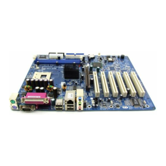
This section outlines how to install and configure your mainboard. Referring to the follow- ing mainboard layout helps you identify various jumpers, connectors, slots, and ports. Steps described herein will lead you to a quick and correct installation of your system. 3.1 Step-by-Step Installation Accessories Of AB49/AB49N CPUFAN1 Two DIMM Slots PWRFAN1... -
Page 16: Step 1 Install The Cpu
Step 1 CPU Installation: This mainboard supports Intel Pentium 4/Celeron Socket 478 series CPU. Please follow the steps as follows to finish CPU installation. Note the CPU orientation when you plug it into CPU socket. 1. Pull up the CPU socket lever to 90-degree angle. CPU socket lever up to 90-degree angle 2. -
Page 17: Step 2 Set Jumpers
Step 2. Set Jumpers The default jumper settings have been set for the common usage standard of this mainboard. Therefore, you do not need to reset the jumpers unless you require special adjustments as any of the following cases: 1. Clear CMOS 2. -
Page 18: Step 4 Install Internal Peripherals In System Case
Step 4 Install Internal Peripherals in System Case Before you install and connect the mainboard into your system case, we recommend that you first assemble all the internal peripheral devices into the computer housing, including but not limited to the hard disk drive (IDE/ HDD), floppy disk drive (FDD), CD-ROM drive, and ATX power supply unit. -
Page 19: Step 5 Mount The Mainboard On The Computer Chassis
Step 5 Mount the Mainboard on the Computer Chassis 1. You may find there are a lot of mounting holes on your computer chassis and mainboard. To match the holes on both properly, the key point is to make the back-panel of the mainboard in a close fit with your system case, as shown below. -
Page 20: Step 6 Connect Front Panel Leds/Switches/Usb
Step 6 Connect Front Panel LEDs/Switches/USB You can find there are several different cables already existing in the system case and originating from the computer's front-panel devices (HDD LED, Green LED, Reset Switch, or a USB device etc.). These cables serve to con- nect the front-panel LEDs, switches, and a USB connector to the mainboard's front-panel connectors, PANEL1 and USB3, as shown below. -
Page 21: Step 7 Connect Ide And Floppy Disk Drives
Step 7 Connect IDE and Floppy Disk Drives 1. IDE cable connectors IDE2 IDE1 2. Floppy cable connector FDD1 - 17 -... -
Page 22: Step 8 Connect Other Internal Peripherals
Step 8 Connect Other Internal Peripherals 1. IR header (IR1) 2. Front panel microphone and line-out header (AUDIO1) and CD_IN connectors (CDIN1/CDIN2) AUDIO1 CDIN1 CDIN2 - 18 -... -
Page 23: Step 9 Connect The Power Supplies
Step 9 Connect the Power Supplies 1. System power connectors (ATX1/ATX12V) ATX1 ATX12V Step 10 Install Add-On Cards in Expansion Slots 1. Accelerated Grapics Port (AGP) Card 2. PCI Card - 19 -... -
Page 24: Step 11 Connect External Peripherals To Back-Panel
Step 11 Connect External Peripherals to Back-Panel You are now ready to connect the external peripherals to your system's back- panel. 1. PS/2 Mouse Port 2. PS/2 Keyboard Port 3. Parallel Port 4. Serial Port 1 5. USB Ports 1/2 6. -
Page 25: Step 12 Install Drivers & Software Components
2000/ME/NT/XP operating systems only. Make sure your operating system is already installed before running the drivers installation CD-ROM programs. 1. Insert the AB49/AB49N bundled CD-ROM into your CD-ROM drive. The auto-run program will display the drivers main installation window on screen. -
Page 26: Jumper Settings
3.2 Jumper Settings Several hardware settings are made through the use of mini jumpers to con- nect jumper pins on the mainboard. Pin #1 could be located at any corner of each jumper, you just find the location with a white right angle which stands for pin #1. -
Page 27: Jumpers & Connectors Guide
Jumpers & Connectors Guide Use the mainboard layout on page 11 to locate CPU socket, memory banks, expansion slots, jumpers and connectors on the mainboard during the instal- lation. The following list will help you to identify jumpers, slots, and connec- tors along with their assigned functions: B4~B5 B6~B8... -
Page 28: Jumpers
Jumpers : Clear CMOS setting : BIOS flash protection setting Back Panel Connectors : PS/2 mouse port : PS/2 keyboard port LPT1 : Parallel port (DB25 female) COM1 : Serial port 1 (DB9 male) : 4 USB (Universal Serial Bus) ports 1/2/3/4 : 1 LAN port (AB49N Only) LINE_IN : Line-In (6-Channel Rear-Out) port... -
Page 29: Clear Cmos Setting (Jp1)
Jumpers Clear CMOS Setting (JP1) JP1 is used to clear CMOS data. Clearing CMOS will result in the perma- nently erasing previous system configuration settings and the restoring origi- nal (factory-set) system settings. Pin 1-2 (Normal)(Default) Pin 2-3 (Clear CMOS) Step 1. -
Page 30: Back-Panel Connectors Ps/2 Mouse & Ps/2 Keyboard Connectors
Back-Panel Connectors PS/2 Mouse & PS/2 Keyboard Connectors Two 6-pin female PS/2 Mouse & Keyboard connectors are located at the rear panel of the mainboard. Depending on the com- PS/2 Mouse puter housing you use (desktop or tower), the PS/2 Mouse connector is situated at the top of the PS/2 Keyboard connector when the mainboard is laid into a desktop, as op- posed to a tower where the PS/2 Mouse... -
Page 31: Lan Port Connector (Ab49N Only)
LAN Port Connector (AB49N Only) LAN Port This mainboard can accommodate one de- vice on LAN. Attach RJ-45 cable to this port connector to your PC to the LAN. Line-In (6-Channel Rear-Out) Port Connector Line-In (Rear-Out) Port Line-In is a stereo line-level input port that accepts a 1/8-inch TRS stereo plug. -
Page 32: Front-Panel Connectors Hdd Led Connector (Hdled)
Front-Panel Connectors HDD LED Connector (HDLED) Attach a connector cable from the IDE device LED to the 2-pin (HDLED) header. The HDD LED lights up whenever an IDE device is active. PANEL1 PWRSW HWRST GRNLED + HDLED Hardware Reset Connector (HWRST) Attach a cable to the 2-pin (HWRST) header. -
Page 33: Green Led Connector (Grnled)
Green LED Connector (GRNLED) The Green LED (GRNLED) indicates that the system is currently in one of the power saving modes (Doze/Standby/Suspend). When the system resumes to the normal operation mode, the Green LED will go off. Attach a cable to the 2- pin (GRNLED) header. -
Page 34: Extended Usb Header (Usb3)
Extended USB Header (USB3) The header is used to connect the cable attached to a USB connector which is mounted on front panel or back panel. But the USB cable is optional at the time of purchase. USB3 USB3 Pin Assignments: 1=VREG_FP_USBPWR0 2=VREG_FP_USBPWR0 3=USB_FP_P0- 4=USB_FP_P1-... -
Page 35: Internal Peripheral Connectors Enhanced Ide And Floppy Connectors (Ide1/Ide2 & Fdd1)
Internal Peripheral Connectors Enhanced IDE and Floppy Connectors (IDE1/IDE2 & FDD1) The mainboard features two 40-pin dual-channel IDE device connectors (IDE1/IDE2), providing support for up to four IDE devices, such as CD-ROM and Hard Disk Drive (HDD). This mainboard also includes one 34-pin floppy disk controller (FDC) to accommodate the Floppy Disk Drive (FDD). -
Page 36: Other Connectors Atx Power Supply Connectors (Atx1/Atx12V)
Other Connectors ATX Power Supply Connectors (ATX1/ATX12V) This motherboard uses 20-pin ATX power header (ATX1), and comes with the other one header (ATX12V). Please make sure you plug each in the right direction. It is essential to have these two power supply connectors plugged or your system won't boot up. -
Page 37: Cpu, Power, And Chassis Fan Connectors (Cpufan1/Pwrfan1/ Casfan1)
CPU, Power, and Chassis Fan Connectors (CPUFAN1/ PWRFAN1/CASFAN1) The mainboard provides three onboard 12V cooling fan power connectors to support CPU (CPUFAN1), Power (PWRFAN1), and Chassis (CASFAN1) cooling fans. +12V SENSE PWRFAN1 CPUFAN1 Note: Both cable wiring and type of plug may vary, which depend on the fan maker. -
Page 38: Ir Header (Ir1)
IR Header (IR1) If you have an Infrared device, this mainboard can implement IR transfer function. This mainboard supports Normal or IrDA transfer mode. To enable this function, attach a 6-pin infrared device cable to the IR (IR1) header, and refer to the diagram below for the IR pin assignments. -
Page 39: System Memory Configuration
3.3 System Memory Configuration The AB49/AB49N mainboard has two 184-pin DIMM banks that allow you to install from 128MB up to 2GB of system memory. Each 184-pin DIMM (Dual In-line Memory Module) bank can accommodate 128MB, 256MB, 512MB, and 1GB of PC1600/PC2100/PC2700 compliant 2.5V single or double side DDR SDRAM modules. -
Page 40: Software Utility
4 SOFTWARE UTILITY 4.1 Mainboard CD Overview Note: The CD contents attached in AB49/AB49N mainboard are subject to change without notice. To start your mainboard CD disc, just insert it into your CD-ROM drive and the CD AutoRun screen should appear. If the AutoRun screen does not appear, double click or run D:\Autorun.exe (assuming that your CD-ROM... -
Page 41: Install Mainboard Software
Insert the attached CD into your CD-ROM drive and the CD AutoRun screen should appear. If the AutoRun screen does not appear, double click on Autorun icon in My Computer to bring up Shuttle Mainboard Software Setup screen. Use your pointing device (e.g. mouse) on the "Install Mainboard AB49 Software"... -
Page 42: A Install Intel Chipset Driver
4.2.A Install Intel Chipset Driver Select using your pointing device (e.g. mouse) on the "Install Intel Chipset driver" bar to install the chipset driver. AB49 AB49N Once you made your selection, a Setup window run the installation automati- cally. When the copying files is done, make sure you reboot the system to take the installation effect. -
Page 43: B Install Intel Ultra Ata Driver
ATA IDE driver. P.S.: Before doing this IDE driver installation, setup chipset system driver is necessary. AB49 AB49N Once you made your selection, a Setup window run the installation automati- cally. When the copying files is done, make sure you reboot the system to take the installation effect. -
Page 44: C Install Usb 2.0 Driver
4.2.C Install USB 2.0 Driver Select using your pointing device (e.g. mouse) on the "Install USB 2.0 Driver" bar to install the USB 2.0 driver. AB49 AB49N Once you made your selection, a Setup window run the installation automati- cally. When the copying files is done, make sure you reboot the system to take the installation effect. -
Page 45: D Install Audio Driver
4.2.D Install Audio Driver Select using your pointing device (e.g. mouse) on the "Install Audio Driver" bar to install the audio driver. AB49 AB49N Once you made your selection, a Setup window run the installation automati- cally. When the copying files is done, make sure you reboot the system to take the installation effect. -
Page 46: E Install Lan Driver (Ab49N Only)
4.3 View the User's Manual Select using your pointing device (e.g. mouse) on the "Manual" bar. Click on the "Install Acrobat Reader" bar if you need to install it, or click on "AB49/AB49N Manual" bar to view user's manual. - 42 -... -
Page 47: Bios Setup
5 BIOS SETUP AB49/AB49N BIOS ROM has a built-in Setup program that allows users to modify the basic system configuration. This information is stored in battery- backed RAM so that it retains the Setup information even if the system power is turned off. -
Page 48: The Main Menu
5.2 The Main Menu Once you enter the AwardBIOS(tm) CMOS Setup Utility, the Main Menu will appear on the screen. The Main Menu allows you to select from several setup functions and two exit choices. Use the arrow keys to select among the items and press <Enter> to accept and enter the sub-menu. - Page 49 PnP/PCI Configurations This entry appears if your system supports PnP/PCI. PC Health Status This entry shows the current system temperature, Voltage, and FAN speed. Frequency/Voltage Control Use this menu to specify your settings for frequency/voltage control. Load Fail-Safe Defaults Use this menu to load the BIOS default values for the minimal/stable performance of your system to operate.
-
Page 50: Standard Cmos Features
Standard CMOS Features The items in Standard CMOS Setup Menu are divided into 10 catego- ries. Each category includes no, one or more than one setup items. Use the arrow keys to highlight the item and then use the <PgUp> or <PgDn>... - Page 51 routine. You can use this item to select which situation you want the BIOS to stop the POST process and notify you. Ø The choice: All Errors, No Errors, All, But Keyboard, All, But Diskette, or All, But Disk/Key. Base Memory/Extended Memory/Total Memory These items are automatically detected by the system at start up time.
-
Page 52: Advanced Bios Features
Advanced BIOS Features This section allows you to configure your system for basic operation. CPU L1 & L2 Cache This item enables CPU L1 internal and CPU L2 cache to speed up memory access. Ø The choice: Enabled or Disabled. CPU Hyper-Threading The latest Intel application defines a high-speed calculating ability to optimize your system by two CPUs supported (one virtual, one physi-... - Page 53 Boot Other Device If you enable this item, the system searches all other possible locations for and operating system if it fails to find one in the devices specified under the First, Second, and Third boot devices. Ø The choice: Enabled or Disabled. Swap Floppy Drive If you have two floppy diskette drives in your system, this item allows you to swap the assigned drive letters so that drive A becomes drive B,...
- Page 54 Security Option If you have installed password protection, this item defines if the pass- word is required at system start up, or if it is only required with a user tries to enter the Setup Utility. Ø The choice: Setup or System. APIC Mode This option is used to enable or disable APIC (Advanced Programmable Interrupt Controller) functionality.
-
Page 55: Advanced Chipset Features
Advanced Chipset Features These items define critical timing parameters of the mainboard. You should leave the items on this page at their default values unless you are very familiar with the technical, specifications of your system hardware. If you change the values incorrectly, you may introduce fatal errors or recurring instability into your system. - Page 56 DRAM RAS# Precharge This item defines the timing delay for DRAM precharge. Ø The Choice: 3 or 2. Command Pre Clock Leave this item at Auto to enhance the system performance. Ø The Choice: Optimal or Auto. DDR Voltage This item defines the DDR voltage. Ø...
-
Page 57: Integrated Peripherals
Integrated Peripherals On-Chip Primary/Secondary PCI IDE The chipset contains a PCI IDE interface with support to two IDE chan- nels. Select Enabled to activate the primary/secondary IDE interface. select Disabled to deactivate the primary/secondary interface. Ø The Choice: Enabled or Disabled. IDE Primary/Secondary Master/Slave PIO The four IDE PIO (Programmed Input/Output) fields let you set a PIO mode (0-4) for each of the four IDE devices that the onboard IDE inter-... - Page 58 USB Controller Select Enabled if your system contains a Universal Serial Bus (USB) port. Ø The choice: Enabled or Disabled. USB 2.0 Controller Select Enabled if your system contains a USB 2.0 controller and you have USB peripherals. Ø The choice: Enabled or Disabled. USB Keyboard Support Select Enabled if you plan to use a USB keyboard in a legacy operating system (such as DOS) that doesn't support Plug and Play.
- Page 59 Onboard FDC Controller This item specifices onboard floppy disk drive controller. Ø The choice: Enabled or Disabled. Onboard Serial Port 1 This option is used to assign the I/O address and interrupt request(IRQ) for the onboard serial port 1 (COM1). Ø...
-
Page 60: Power Management Setup
Power Management Setup The Power Management Setup allows you to configure your system to most effectively saving energy while operating in a manner consistent with your own style of computer use. ACPI Function This item defines the ACPI (Advanced Configuration and Power Man- agement) feature that makes hardware status information available to the operating system, enables a PC to turn its peripherals on or off for improving the power management, and allows a PC turned on or off by... - Page 61 Power Management This item acts like a master switch for the power-saving modes and hard disk timeouts. If this item is set to Max Saving, power-saving modes occur after a short timeout. If it is set to Min Saving, power-saving modes occur after a longer timeout.
- Page 62 Soft-Off by PWR-BTTN Under ACPI you can create a software power down. In a software power down, the system can be resumed by Wake UP Alarms. This item lets you install a software power down that is controlled by the power button on your system.
- Page 63 ** Reload Global Timer Events ** Global Timer (power management) Events are I/O events whose occur- rence can prevent the system from entering a power saving mode or can awaken the system from such as a mode. In effect, the system remains alert for anything that occurs to a device that is configured as Enabled, even when the system is in a power-down mode.
-
Page 64: Pnp/Pci Configurations
PnP/PCI Configurations This category configures how PnP and PCI operate in your system. Correctly setting up the IRQ and DMA (both PnP and PCI use) assign- ments will make your system work stably. It is strongly recommended that only technical users make changes to the default settings. Reset Configuration Data When Enabled, any PnP configuration data stored in the BIOS will be cleared from memory, with new data created. -
Page 65: Pc Health Status
PC Health Status Shutdown Temperature Enables you to set the maximum temperature that system can reach before powering down. Ø The choice: Disabled, 60°C/140°F, 65°C/149°F, 70°C/158°F, or 75°C/167°F. Warning Temperature Enables you to set the warning temperature level for the processor. Ø... -
Page 66: Frequency/Voltage Control
Frequency/Voltage Control CPU Clock Ratio This item allows you to adjust CPU Ratio. The item becomes unavail- able if your CPU clock ratio is locked. CPU Core Voltage This item defines the CPU core voltage. Ø The choice: Vcore Auto, Vcore 1.5%, Vcore 3.0%, or Vcore 4.5%. Auto Detect DIMM/PCI CLK When this item is enabled, BIOS will disable the clock signal of free DIMM and PCI slots. -
Page 67: Load Fail-Safe Defaults
Load Fail-Safe Defaults When you press <Enter> on this item, you will get a confirmation dialog box with a message similar to: Load Fail-Safe Defaults (Y/N) ? N Pressing 'Y' loads the BIOS default values for the most stable, minimal performance system operations. - Page 68 Set Supervisor/User Password Steps to set supervisor/user password are described as follows: New Password Setting: 1. While pressing <Enter> to set a password, a dialog box appears to ask you enter a password. 2. Key in a new password. The password can not exceed eight charac- ters.
- Page 69 Save & Exit Setup Pressing <Enter> on this item asks for confirmation: SAVE to CMOS and EXIT (Y/N)? Y Pressing "Y" stores the selections made in the menus of CMOS - a special section of memory that stays on after you turn your system off. The next time you boot your computer, the BIOS configures your system according to the Setup selections stored in CMOS.
Need help?
Do you have a question about the AB49 and is the answer not in the manual?
Questions and answers