Table of Contents
Advertisement
Quick Links
Advertisement
Table of Contents

Subscribe to Our Youtube Channel
Related Manuals for Shuttle AB60P


Summary of Contents for Shuttle AB60P
- Page 1 AB60P Pentium 4/Celeron 478-pin Processor Based MAIN BOARD User's Manual...
- Page 2 The information contained in this manual is provided for general use by the customers. Trademarks Shuttle is a registered trademark of Shuttle Inc. Intel, Pentium is a registered trademarks of Intel Corporation. PS/2 is a registered trademark of IBM Corporation.
- Page 3 Statement of Shuttle Mainboard via the EMI Test Shuttle mainboards have been via the EMI test in terms of series of regulations: EN55022/ CISPR22/AS/NZS3548 Class B, EN55024 (1998/AS/NZS), EN4252.1 (1994), EN61000, ANSI C63.4 (1992), CFR47 Part 15 Subpart B, and CNS13438 (1997). The items tested are illus- trated as follows: (A) Voltage: AC 110V/60HZ &...
- Page 4 Remedy: N/A EMI Interference: Crystal: 14.318MHz(X2)/ 25.00MHz(X4)/ 32.768KHz(X1) Clock Generator: CLK1 (D) Supported Host Peripherals: Host Peripheral Product Name Model Name Case AB60P Power Supply (300W) ENP-0730 Maxtor HDD (40 GB) D740X-6L Pioneer DVD Player DVD-116 Power Cable Detachable and Shielded...
-
Page 5: Table Of Contents
2.1 SPECIFICATIONS ..................8 3 HARDWARE INSTALLATION ............11 3.1 STEP BY STEP INSTALLATION ..............11 Accessories of AB60P ................11 STEP 1 Install the CPU ................12 STEP 2 Set Jumpers ................13 STEP 3 Install DDR System Memory ............. 13 STEP 4 Install Peripherals in System Case .......... - Page 6 3.2 JUMPER SETTINGS ................. 24 JUMPERS & CONNECTORS GUIDE ............ 25 Jumpers Clear CMOS Setting (JP2) ..............28 On Board LAN Setting (JP7) ..............28 CPU Frequency Setting (JP3) .............. 29 5V/ 5VSB Setting (JP5/JP6) ..............29 Back-Panel Connectors PS/2 Keyboard & PS/2 Mouse Connectors ..........30 Parallel Port Connector ................
- Page 7 Enhanced IDE and Floppy Connectors ..........35 Serial ATA Connectors ................35 Other Connectors ATX Power Supply Connectors (ATX1 & ATX2) ........36 Cooling Fan Connectors for Chipset (FAN1), CPU (FAN2), AGP(FAN3) 37 IR Header (J1) ..................37 CD-IN Connectors (J7/J8) ..............38 Audio Auxiliary_IN Connector (J9) ............
- Page 8 5.2 THE MAIN MENU ..................47 STANDARD CMOS FEATURES ............... 49 ADVANCED BIOS FEATURES ..............53 ADVANCED CHIPSET FEATURES ............57 INTEGRATED PERIPHERALS ..............60 POWER MANAGEMENT SETUP .............. 66 PNP/PCI CONFIGURATION............... 71 PC HEALTH STATUS ................73 FREQUENCY/VOLTAGE CONTROL ............74 LOAD FAIL-SAFE DEFAULTS ..............
-
Page 9: What's In The Manual
WHAT'S IN THE MANUAL Quick Reference Hardware Installation >> Step-by-Step ..........Page 11 Jumper Settings >> A Closer Look ............Page 24 Software Utilities >> How to Install ............Page 41 BIOS Setup >> How to Configure ............Page 46 About This Manual For First-Time DIY System Builder ............ -
Page 10: Introduction
Experienced DIY User Congratulate on your purchase of the Shuttle AB60P mainboard. You will find that installing your new Shuttle AB60P mainboard is just easy. Bundled with an array of onboard functions, the highly-integrated AB60P mainboard provides you with a total solution to build the most stable and reliable system. Refer to sections 3.2 Jumper Settings and Chapter 4 Drivers/Software Utilities to... -
Page 11: Item Checklist
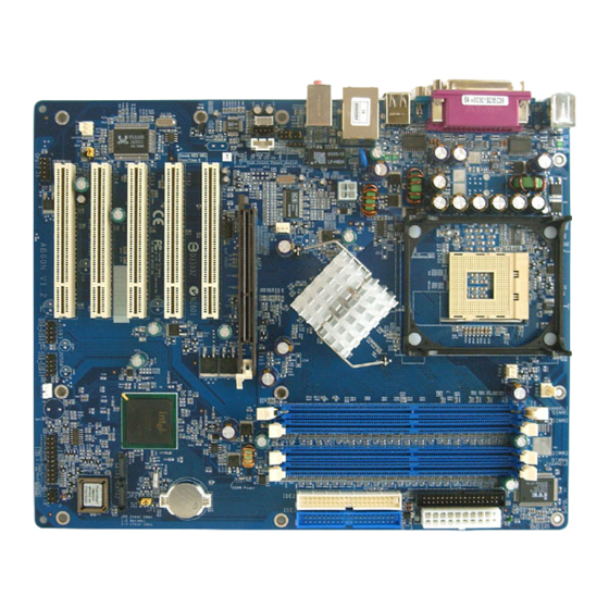
1.2 Item Checklist Check all items with your AB60P mainboard to make sure nothing is missing. The complete package should include: FAN2 - One piece of Shuttle AB60P Mainboard DIMM1 DIMM2 COM1 JUSB1 JUSB2LAN1 FAN1 AUDIO1 AGP1 FAN3 PCI1 PCI2... -
Page 12: Features
2 FEATURES AB60P mainboard is carefully designed for the demanding PC user who wants high perfor- mance and maximum intelligent features in a compact package. 2.1 Specifications - CPU Support Intel Pentium 4/Celeron, 478-pin processors with 400/533/800 MHz FSB. Supports Prescott CPU. (Don't support Willmette CPU.) - Chipset Features Intel 848-P N.B. - Page 13 Ø 1 X Floppy interface for 3.5-inch FDD with 720KB, 1.44MB, or 2.88MB format or for 5.25-inch FDD with 360K or 1.2MB format. Ø 1 X PS/2 mouse connector. Ø 1 X PS/2 Keyboard connector. Ø 4 X USB ports. Ø...
- Page 14 - Advanced Features Ø Low EMI - Built in spread spectrum and automatic clock shut-off of unused PCI/DDR-SDRAMS slots to reduce EMI. Ø Dual Function Power Button - The system can be in one of two states, one is Suspend mode and the other is Soft-Off mode. Pushing the power button for less than 4 seconds places the system into Suspend mode.
-
Page 15: Hardware Installation
Then follow these steps designed to guide you through a quick and correct installation of your system. 3.1 Step-by-Step Installation Accessories Of AB60P ATX 12V Power Connector - ATX2 CPU FAN - FAN2... -
Page 16: Step 1 Install The Cpu
Step 1 CPU Installation: This mainboard supports Intel Pentium 4/Celeron Socket 478 series CPU. Please follow the steps as follows to finish CPU installation. Note the CPU orientation when you plug it into CPU socket. 1. Pull up the CPU socket lever to 90-degree angle. CPU socket lever up to 90-degree angle 2. -
Page 17: Step 2 Set Jumpers
Step 2 Set Jumpers The default jumper settings have been set for the common usage standard of this mainboard. Therefore, you do not need to reset the jumpers unless you require special adjustments as any of the following cases: 1. Clear CMOS 2. -
Page 18: Step 4 Install Peripherals In System Case
Step 4 Install Internal Peripherals in System Case Before you install and connect the mainboard into your system case, we rec- ommend that you first assemble all the internal peripheral devices into the com- puter housing, including but not limited to the hard disk drive (IDE/HDD), floppy disk drive (FDD), CD-ROM drive, and ATX power supply unit. -
Page 19: Step 5 Mount The Mainboard On The Computer Chassis
the back-panel of each peripheral device. Note that the power cable is directional and cannot fit in if not properly positioned. Step 5 Mount the Mainboard on the Computer Chassis 1. You may find that there are a lot of different mounting hole positions both on your computer chassis and on the mainboard. -
Page 20: Step 6 Connect Front Panel Switches/Leds/Speaker/Usb
Step 6 Connect Front Panel Switches/LEDs/Speaker/USB connectors You can find there are several different cables already existing in the system case and originating from the computer's front-panel devices (HDD LED, Power LED, Reset Switch, PC Speaker, or USB devices etc.) These cables serve to con- nect the front-panel switches, LEDs, and USB connectors to the mainboard's front-panel connectors group, as shown below. -
Page 21: Step 7 Connect Ide And Floppy Disk Drives
Step 7 Connect IDE and Floppy Disk Drives 1. IDE cable connector 2. Floppy cable connector 3. Serial ATA cable connector SATA2 SATA1 - 17 -... -
Page 22: Step 8 Connect Other Internal Peripherals
Step 8 Connect Other Internal Peripherals 1. CD-IN, AUX-IN (J7/ J8 ,J9) CD-IN CD-IN AUX-IN 2. IR header (J1) - 18 -... - Page 23 3. SPDIF In/Out header (J5) SPDIF 4. Front Panel Audio header (J4) Front Panel Audio - 19 -...
-
Page 24: Step 9 Connect The Power Supply
Step 9 Connect the Power Supply 1. System power connector (ATX1/ATX2) ATX2 Step 10 Install Add-on Cards in Expansion Slots 1. Accelerated Graphics Port (AGP) Card 2. PCI Card - 20 -... -
Page 25: Step 11 Connect External Peripherals To Back Panel
Step 11 Connect External Peripherals to Back-Panel You are now ready to put the computer case back together and get on to the external peripherals connections to your system's back-panel. 1. PS/2 Mouse & PS/2 Keyboard 2. Parallel Port 3. COM1 Port 4. -
Page 26: Step 12 First Time System Boot Up
Step 12 First Time System Boot Up To assure the completeness and correctness of your system installation, you may check the above installation steps once again before you boot up your system for the first time. 1. Insert a bootable system floppy disk (DOS 6.2x, Windows 95/98/NT, or others) which contains FDISK and FORMAT utilities into the FDD. -
Page 27: Step 13 Install Drivers & Software Components
/2000/ME/XP/NT operating systems only. Make sure your operating system is already installed before running the drivers installation CD-ROM programs. 1. Insert the AB60P bundled CD-ROM into your CD-ROM drive. The autorun program will display the drivers main installation window on screen. -
Page 28: Jumper Settings
3.2 Jumper Settings Several hardware settings are made through the use of jumper caps to connect jumper pins to the mainboard. Pin #1 could be located at any corner of each jumper; you just find a location marked with a while right angle, which stands for pin1#. -
Page 29: Jumpers & Connectors Guide
Jumpers & Connectors Guide Use the mainboard layout on page 11 to locate CPU socket, memory banks, expansion slots, jumpers and connectors on the mainboard during the installa- tion. The following list will help you to identify jumpers, slots, and connectors along with their assigned functions: B2~B4 B6~B7... -
Page 30: Jumpers
Jumpers : Clear CMOS setting : LAN Enable/Disable : CPU Frequency Select JP5 /JP6 : 5V/ 5VSB Select Back Panel Connectors : PS/2 keyboard port : PS/2 mouse port Parallel : Printer port COM1 : Serial port COM2 : Serial port USB0/1 : 2 x USB ports : LAN port... - Page 31 SATA1/2 : Serial ATA interface Other Connectors ATX1/ATX2 : ATX power connectors FAN1 : Chipset fan connector FAN2 : CPU fan connector FAN3 : AGP fan connector : IR header J7/J8 : CD-IN 1/2 headers : AUX-IN header : Front Panel Audio header : SPDIF In/Out header - 27 -...
-
Page 32: Clear Cmos Setting (Jp2)
Jumpers Clear CMOS Setting (JP2) JP2 is used to clear CMOS data. Clearing CMOS will result in the permanently erasing previous system configuration settings and the restoring original(factory- set) system settings. Pin 1-2 (Default) Pin 2-3 (Clear CMOS) Step 1. Turn off the system power (PC-> Off). Step 2. -
Page 33: Cpu Frequency Setting (Jp3)
CPU Frequency Setting (JP3) JP3 is used to select CPU frequency (100MHz, 133 MHz or 200 MHz) accord- ing to the CPU. Reference below table. JP3 CPU Freq Freq Auto 5V/5VSB Setting (JP5/JP6) JP5/JP6 is used to select 5V or 5VSB when USB devices want to resume from 5V/5VSB Select Pin 1-2 5V (Default) Pin 2-3 5VSB... -
Page 34: Back-Panel Connectors Ps/2 Keyboard & Ps/2 Mouse Connectors
Back-Panel Connectors PS/2 Keyboard & PS/2 Mouse Connectors Two 6-pin female PS/2 keyboard & Mouse connectors are located at the rear panel PS/2 Mouse of the mainboard. Depending on the com- puter housing you use (desktop or tower), the PS/2 Mouse connector is situated at the top of the PS/2 Keyboard connector when the mainboard is laid into a desk- top, as opposed to a tower where the PS/2... -
Page 35: Lan Port Connector
LAN Port Connector This mainboard can accommodate one device on LAN. Attach a 10/100 baseT cable to the RJ45 LAN port at the back-panel of your computer. USB2/USB3 Port Connectors USB port3 This mainboard offers 2 USB ports on back panel. -
Page 36: Front-Panel Connectors Hdd Led Connector (Hled)
Front-Panel Connectors HDD LED Connector (HLED) Attach the connector cable from the IDE device LED to the 2-pin (HLED) header. The HDD LED lights up whenever an IDE device is active. Front Panel SPEAKER EPMI RST HLED GLED Hardware Reset Connector (RST) Attach the 2-pin hardware reset switch cable to the (RST) header. -
Page 37: Speaker Connector (Speaker)
Speaker Connector (SPEAKER) Attach the PC speaker cable from the case to the 4-pin speaker connector (SPEAKER). Front Panel SPEAKER EPMI RST HLED GLED Green LED Connector (GLED) The Green LED (GLED) Indicates that the system in currently in one of the power saving modes (Doze/Standby/Suspend). -
Page 38: Power Led Connector (Pwrled)
Power LED Connector (PWRLED) Attach the 3-pin Power-LED connector cable from the housing front-panel to the (PWRLED) header on the mainboard. The power LED stays light while the system is running. Front Panel SPEAKER EPMI RST HLED GLED Extended USB Connectors (JUSB3/JUSB4) The headers are used to connect the cable attached to USB connectors which are mounted on front-panel or back-panel. -
Page 39: Internal Peripherals Connectors
Internal Peripherals Connectors Enhanced IDE and Floppy Connectors The mainboard features two 40-pin dual-channel IDE device connectors (IDE1/ IDE2) providing support for up to four IDE devices, such as CD-ROM and Hard Disk Drives (H.D.D.). This mainboard also includes one 34-pin floppy disk controller (FDD1) to ac- commodate the Floppy Disk Drive (FDD). -
Page 40: Other Connectors Atx Power Supply Connectors (Atx1 & Atx2)
Other Connectors ATX Power Supply Connectors (ATX1 & ATX2) This motherboard uses 20-pin Pentium 4 standard ATX power header, and ATX2 with 2x2-pin PC ATX power supply headers. Please make sure you plug in the right direction. ATX1 ATX2 ATX2 Note 1 : The ATX power connector is directional and will not go in unless the guides match perfectly making sure that pin#1 is properly positioned. -
Page 41: Cooling Fan Connectors For Chipset (Fan1), Cpu (Fan2), Agp(Fan3)
CPU, CAS, and PWR Fan connectors (FAN1/FAN2/FAN3) The mainboard provides four onboard 12V cooling fan power connectors to support Chipset(FAN1) , CPU(FAN2) and AGP(Fan3) cooling fans. FAN2 Note: Both cable wiring and type of plug may vary , which depends on the fan maker. -
Page 42: Cd-In Connectors (J7/J8)
CD_IN Connectors (J7/J8) Port J7/J8 is used to attach an audio connector cable from the CD-ROM drive. 1 2 3 4 J7 Pins Assignments: 1=Ground 2=CD-IN-R 3=Ground 4=CD-IN-L 4 3 2 1 J8 Pins Assignments: 1=CD-IN-L CD-IN J8 CD-IN 2=Ground 3=Ground 4=CD-IN-R Audio AUXILIARY_IN Connector (J9) -
Page 43: Front Panel Audio Connector (J4)
Front Panel Audio Connector (J4) This header allows the user to install auxiliary front-oriented micorophone and line-out ports for easier access. Pin Assignments: Front Panel 1=AUD_MIC Audio 2=AUD_GND 3=AUD_MIC_BIAS 4=AUD_VCC 5=AUD_FPOUT_R 6= AUD_RET_R 7=NC 8=KEY 9=AUD_FPOUT_L 10=AUD_RET_L Two mini jumpers must be setted on pin 5-6 and pin 9-10, when this header is not used. -
Page 44: System Memory Configuration
3.3 System Memory Configuration The AB60P mainboard has two 184-pin DIMM slots that allow you to install from 64MB up to 2GB of system memory. Each 184-pin DIMM Slot can ac- commodate 64MB, 128MB, 256MB, 512MB, and 1GB of PC2100, PC2700 or PC3200 compliant 2.5V single (1 Bank) or double (2 Bank) side 64-bit wide... -
Page 45: Software Utility
4 SOFTWARE UTILITY 4.1 Mainboard CD Overview Note : The CD contents attached in AB60P mainboard are subject to change without notice. To start your mainboard CD disc, just insert it into your CD-ROM drive and the CD AutoRun screen should appear. If the AutoRun screen does not appear, double click or run D:\Autorun.exe (assuming that your CD-ROM drive is... -
Page 46: Install Mainboard Software
Insert the attached CD into your CD-ROM drive and the CD AutoRun screen should appear. If the AutoRun screen does not appear, double click on Autorun icon in My Computer to bring up Shuttle Mainboard Software Setup screen. Select using your pointing device (e.g. mouse) on the "Install Mainboard Software"... -
Page 47: A Install Intel Chipset Driver
4.2.A Install Intel Chipset Driver Select using your pointing device (e.g. mouse) on the "Install Intel Chipset Driver" bar to install Intel chipset driver. Once you made your selection, a Setup window run the installation automati- cally. When the copying files is done, make sure you reboot the system to take the installation effect. -
Page 48: C Install Realtek Audio Driver
4.2.C Install Realtek Audio Driver Select using your pointing device (e.g. mouse) on the "Install Realtek Audio Driver" bar to install audio driver. Once you made your selection, a Setup window run the installation automati- cally. When the copying files is done, make sure you reboot the system to take the installation effect. -
Page 49: View The User's Manual
Insert the attached CD into your CD-ROM drive and the CD AutoRun screen should appear. If the AutoRun screen does not appear, double click on AutoRun icon in My Computer to bring up Shuttle Mainboard Software Setup screen. Select using your pointing device (e.g. mouse) on the “Manual" bar. -
Page 50: Bios Setup
5 BIOS SETUP AB60P BIOS ROM has a built-in Setup program that allows users to modify the basic system configuration. This information is stored in battery-backed RAM so that it retains the Setup information even if the system power is turned off. -
Page 51: The Main Menu
5.2 The Main Menu Once you enter the AwardBIOS(tm) CMOS Setup Utility, the Main Menu will appear on the screen. The Main Menu allows you to select from sev- eral setup functions and two exit choices. Use the arrow keys to select among the items and press <Enter>... - Page 52 PnP / PCI Configurations This entry appears if your system supports PnP / PCI. PC Health Status This entry shows the current system temperature, Voltage, and FAN speed. Frequency/Voltage Control Use this menu to specify your settings for frequency/voltage control. Load Fail-Safe Defaults Use this menu to load the BIOS default values for the minimal/stable per- formance of your system to operate.
-
Page 53: Standard Cmos Features
Standard CMOS Features The items in Standard CMOS Setup Menu are divided into 10 categories. Each category includes no, one or more than one setup items. Use the arrow keys to highlight the item and then use the <PgUp> or <PgDn> keys to select the value you want in each item. - Page 54 IDE Channel 1 Master Options are in its sub-menu. Press <Enter> to enter the sub-menu of detailed options. IDE Channel 1 Slave Options are in its sub menu. Press <Enter> to enter the sub-menu of detailed options. Drive A/Drive B Select the type of floppy disk drive installed in your system.
- Page 55 ****************************************************** IDE Adapters The IDE adapters control the hard disk drive. Use a separate sub-menu to configure each hard disk drive. IDE HDD Auto-Detection Press <Enter> to auto-detect HDD on this channel. If detection is successful, it fills the remaining fields on this menu. Ø...
- Page 56 Precomp Warning: Setting a value of 65535 means no hard disk. Ø Min = 0, Max = 65535 Landing zone Set the Landing zone size. Ø Min = 0, Max = 65535 Sector Number of sector per track. Ø Min = 0, Max = 255 ****************************************************** - 52 -...
-
Page 57: Advanced Bios Features
Advanced BIOS Features This section allows you to configure your system for basic operation. You have the opportunity to select the system's default speed, boot-up sequence, keyboard operation, shadowing, and security. Hard Disk Boot Priority This item allows you to select Hard Disk Boot Device Priority. Bios Write Protect This item allows you to enable or disable the Bios Write Protect. - Page 58 Disabled No warning message will appear when anything attempts to access the boot sector or hard disk partition table. Ø The choice: Enabled or Disabled. CPU L1&L2 Cache All processors that can be installed in this mainboard use internal level1(L1) and external 2(L2) cache memory to imporve performance.
- Page 59 Boot Up Floppy Seek Seeks disk drives during boot-Up. Disabling speed boots up. Ø The choice: Enabled or Disabled. Boot Up NumLock Status Selects power-on state for NumLock. Ø The choice: Off or On. Gate A20 Option This entry allows you to select how the gate A20 is handled. The gate A20 is a device used for above 1MBye of address memory.
- Page 60 Setup The system will boot, but access to Setup will be denied if the correct password is not entered promptly. Ø The choice: System or Setup. Note: To disabled security, select PASSWORD SETTING at Main Menu, and then you will be asked to enter password. Don't type anything and just press<Enter>;...
-
Page 61: Advanced Chipset Features
Advanced Chipset Features This section allows you to configure the system based on the specific features of the installed chipset. This chipset manages bus speeds and access to sys- tem memory resources, such as DRAM and the external cache. It also coor- dinates communications between the conventional ISA bus and the PCI bus. - Page 62 Active to Precharge Delay This item select the SDRAM Active to Precharge Delay. (8T, 7T, 6T, or 5T) Ø The Choice: 8, 7, 6 or 5. DRAM RAS# to CAS# Delay This field lets you insert a timing delay between the CAS and RAS strobe signals, and you can use it when DRAM is written to, read from, or refreshed.
- Page 63 System BIOS Cacheable Selecting Enabled allows caching of the system BIOS ROM at F0000h- FFFFFh, resulting in better system performance. However, if any pro- gram is written to this memory area, a system error may result. Ø The choice: Enabled or Disabled. Video BIOS Cacheable Selecting Enabled allows caching of the video BIOS , resulting in better system performance.
-
Page 64: Integrated Peripherals
Integrated Peripherals These options display items that define the operation of peripheral comopnents on the system's input/output ports. On-Chip IDE Device Options are in its sub-menu. Press<Enter> to enter the sub-menu of details options. IDE HDD Block Mode Block mode is also called block transfer, multiple commands, or mul- tiple sector read/write. - Page 65 IDE Primary Master/Primary Slave/Secondary Master/ Second ary Slave PIO Each IDE channel supports a master device and a slave device. These four items let you assign which kind of PIO ( Programmed Input / Out- put ) is used by IDE devices. Choose Auto to let the system auto detect which PIO mode is best or select a PIO mode from 0-4.
- Page 66 Combined Mode: PATA and SATA are combined. Max. of 2 ATA drives in each channel. (DOS,Win2K,Win98/ME...) should set SATA and PATA to Compatible Mode. Serial ATA 1 (Channel 0) Serial ATA 1 (Channel 0) Slave Master Primary Primary Master Slave Serial ATA 2 (Channel 0) (Channel 0)
- Page 67 Enhanced Mode: Enable both SATA and PATA. Max. of 6 ATA drives are supported. New OS that support switch to Enhanced mode (WinXP,Windows.NET Server) can set SATA and PATA to Enhanced Mode. Serial ATA 1 (Channel 2) Primary Master or Secondary (Channel 3) Serial ATA 2 (Channel 3)
- Page 68 Serial ATA Port0/1 Mode This item allows you to set the Serial ATA Port mode. Ø The choice: Primary Master, Primary Slave, Secondary Master, Secondary Slave, SATA0 master or SATA1 master. Onboard Device Options are in its sub-menu. Press<Enter> to enter the sub-menu of details options. USB Controller Select Enabled if your system contains a Universal Serial Bus (USB) controller and you have USB peripherals.
- Page 69 Onboard FDC Controller This item specifices onboard floppy disk drive controller. This setting allows you to connect your floppy disk drives to the onboard floppy connector. Choose the "Disabled" settings if you have a separate control card. Ø The choice: Enabled or Disabled. Onboard Serial Port1/Port2 Select an address and corresponding interrupt for the first and second serial ports.
-
Page 70: Power Management Setup
Power Management Setup The Power Management Setup allows you to configure your system to most effectively saving energy while operating in a manner consistent with your own style of computer use. ACPI Function This item is the Advanced Configuration and Power Management (ACPI), it always Enable and Gray. - Page 71 Power Management This category allows you to select the type (or degree) of power saving and is directly related to the following modes: Min Saving Minimum power management. Suspend Mode= 1 hr. HDD Power Down=15min. Max Saving Maximum power management. Suspend Mode=1min.
- Page 72 Suspend Mode When this item enabled and after the set up time of system inactivity, all devices except the CPU will be shut off. Ø The choice: Disabled, 1 Min, 2 Min, 4 Min, 8 Min, 12 Min, 20 Min, 30 Min, 40 Min or 1 Hour. HDD Power Down When this item enabled and after the set up time of system inactivity, the hard disk drive will be powered down while all other devices remain...
- Page 73 Data (of Month) Alarm This item selects the alarm date. Ø Key in a DEC number:Min=0, Max=31. Time (hh:mm:ss) Alarm This item selects the alarm Time. [hh] Ø Key in a DEC number:Min=0, Max=23. [mm/ss] Ø Key in a DEC number:Min=0, Max=59. *** Reload Global Timer Events *** Primary/Secondary IDE0/1 When these items are enabled, the system will restart the power-saving...
- Page 74 Hot Key Power ON Power-on by soft-on/off button and keyboard are available. Ø The choice: Any Key, Ctrl-F1~Ctrl-F12. PS2 Mouse Power ON This item allows you to set the PS2 Mouse Power ON function.. Ø The choice: Enabled or Disabled. PWRON After PWR-Fail This item allows you to set whether you want your system to reboot after power hav been interrupted.
-
Page 75: Pnp/Pci Configuration
PnP/PCI Configurations This section describes the configuration of PCI bus system. PCI or Personal Computer Interconnection is a system which allows I/O devices to operate at the speed CPU itself keeps when CPU communicat- ing with its own special components. This section covers some very tech- nical items, and it is strongly recommended that only experienced users should make any changes to the default settings. - Page 76 IRQ Resources When resources are controlled manually, assign each system interrupt a type, depending on the type of device using the interrupt. IRQ3/4/5/7/9/10/11/12/14/15 assigned This item allows you to determine the IRQ assigned to the ISA bus and is not available to any PCI slot. Legacy ISA for devices is compliant with the original PC AT bus specification;...
-
Page 77: Pc Health Status
PC Health Status Shutdown Temperature Enables you to set the maximum temperature the system can reach be- fore powering down. Ø The choice: 60 C/140 F, 65 C/149 F, 70 C/158 F or 75 C/167 System Component Characteristics These fields provide you with information about the systems current operating status. -
Page 78: Frequency/Voltage Control
Frequency/Voltage Control CPU Clock Ratio This item allows you to adjust CPU Ratio. If your CPU ratio is unlocked, the item is visible. Min: 8 Max: 50 Ø Key in a DEC number: (Between Min and Max.) Auto Detect PCI Clk This item allows you to enable/disable auto disable empty PCI Slot Clock. -
Page 79: Load Fail-Safe Defaults
CPU Clock This item allows the user to adjust CPU Host Clock. Ø The choice: 100 MHz~233 MHz. Load Fail-Safe Defaults When you press <Enter> on this item, you will get a confirmation dialog box with a message similar to: Load Fail-Safe Defaults (Y/N) ? N Pressing 'Y' loads the BIOS default values for the most stable, minimal performance system operations. -
Page 80: Set Supervisor/ User Password
Supervisor/User Password Setting You can set either supervisor or user password, or both of them. The differences between them are: Supervisor Password and User Password The options on the Password screen menu make it possible to restrict access to the Setup program by enabling you to set passwords for two different access modes: Supervisor mode and User mode. -
Page 81: Save & Exit Setup
Password Disable If you select System at Security Option of BIOS Features Setup Menu, you will be prompted in entering the password whenever the system is rebooted or you try to enter Setup. If you select Setup at Security Option of BIOS Features Setup Menu, you will be prompted only when you try to enter Setup.
Need help?
Do you have a question about the AB60P and is the answer not in the manual?
Questions and answers