
Related Manuals for Shuttle AK32V


Summary of Contents for Shuttle AK32V
- Page 1 AK32V/AK32VN SocketA AMD Athlon XP/Athlon/Duron Processor Based DDR Main Board User's Manual...
- Page 2 The information contained in this manual is provided for general use by the customers. Trademarks Shuttle is a registered trademark of Shuttle Inc. VIA is a registered trademark of VIA Corporation. AMD, Athlon/Duron are registered trademarks of AMD Corporation.
- Page 3 Statement of Shuttle Mainboard via the EMI Test Shuttle mainboards have been via the EMI test in terms of series of regulations: EN55022/ CISPR22/AS/NZS3548 Class B, EN55024 (1998/AS/NZS), EN4252.1 (1994), EN61000, ANSI C63.4 (1992), CFR47 Part 15 Subpart B, and CNS13438 (1997). The items tested are illus- trated as follows: (A) Voltage: AC 110V/60HZ &...
- Page 4 Remedy: N/A EMI Interference: Crystal: 14.318MHz(X3)/32.768 KHz(X4)/24.576 MHz(X1)/25.00 MHz(X2) Clock Generator: U13 (D) Supported Host Peripherals: Host Peripheral Product Name Model Name FCC ID Case AK32V Power Supply (300W) Seventeam ST-250HK IBM HDD (82.3GB) IC35L080AVVA07-0 A4DEENPG 3902I082 MITSUMI FDD D353M3...
-
Page 5: Table Of Contents
TABLE OF CONTENTS WHAT'S IN THE MANUAL ..............5 Quick Reference ....................5 About This Manual ................... 5 1 INTRODUCTION ................6 1.1 TO DIFFERENT USERS ................6 First-Time DIY System Builder ..............6 Experienced DIY User ................6 System Integrator ..................6 1.2 ITEM CHECKLIST .................. - Page 6 3.2 JUMPER SETTINGS ................. 23 JUMPER & CONNECTOR GUIDE............24 Jumpers Clear CMOS Setting (JP1) ..............26 CPU Frequency select (JP2) ..............26 Back-Panel Connectors PS/2 Keyboard & PS/2 Mouse Connectors ..........27 Parallel Port Connector ................27 COM1 Connector .................. 27 USB Port Connectors ................
- Page 7 3.3 SYSTEM MEMORY CONFIGURATION ............. 36 Install Memory ..................36 Upgrade Memory ................... 36 4 SOFTWARE UTILITY ..............37 4.1 Mainboard CD Overview ................. 37 4.2 Install Mainboard Software ..............38 4.2A Install VIA 4in1 Driver ................39 4.2.B Install VIA LAN Driver (AK32VN only) ..........40 4.2.C Install VIA Audio Driver ...............
- Page 8 SAVE & EXIT SETUP ................73 EXIT WITHOUT SAVING ................73 - 4 -...
-
Page 9: What's In The Manual
WHAT'S IN THE MANUAL Quick Reference Hardware Installation >> Step-by-Step ..........Page 11 Jumper Settings >> A Closer Look ............Page 23 Software Utility >> How to Install ............Page 37 BIOS Setup >> How to Configure ............Page 44 About This Manual For First-Time DIY System Builder ............ -
Page 10: Introduction
Experienced DIY User Congratulate on your purchase of the Shuttle AK32V/AK32VN mainboard. You will find that installing your new Shuttle AK32V/AK32VN mainboard is just easy. Bundled with an array of onboard functions, the highly-integrated AK32V/ AK32VN mainboard provides you with a total solution to build the most stable and reliable system. -
Page 11: Item Checklist
1.2 Item Checklist Check all items with your AK32V/AK32VN mainboard to make sure nothing is missing. The complete package should include: - One piece of Shuttle AK32V/AK32VN Mainboard SOCKET462 CASFAN1 SPK1 - One piece of ATA133/100/66/33 Ribbon Cable - One piece of Floppy Ribbon Cable - One piece of twin ports USB2.0 Cable (optional) -
Page 12: Features
2 FEATURES AK32V/AK32VN mainboard is carefully designed for the demanding PC user who wants high performance and maximum intelligent features in a compact package. 2.1 Specifications - CPU Support Support Socket462 package CPU AMD Athlon XP Processor with 200/266 MHz FSB... - Page 13 - I/O Interface Provides a variety of I/O interfaces: Ø 1 x Floppy interface for 3.5-inch FDD with 720KB, 1.44MB, or 2.88MB format or for 5.25-inch FDD with 360K or 1.2MB format. Ø 1 x PS/2 mouse connector. Ø 1 x PS/2 Keyboard connector. Ø...
- Page 14 - System BIOS Provides licensed Award BIOS V6.0 PG on 2Mb Flash EEPROM and supports Green PC, Desktop Management Interface (DMI). - Form Factor System board conforms to the ATX specification. Board dimension: 305mm* 190mm. - Advanced Features Ø Dual Function Power Button - The system can be in one of two states ;...
-
Page 15: Hardware Installation
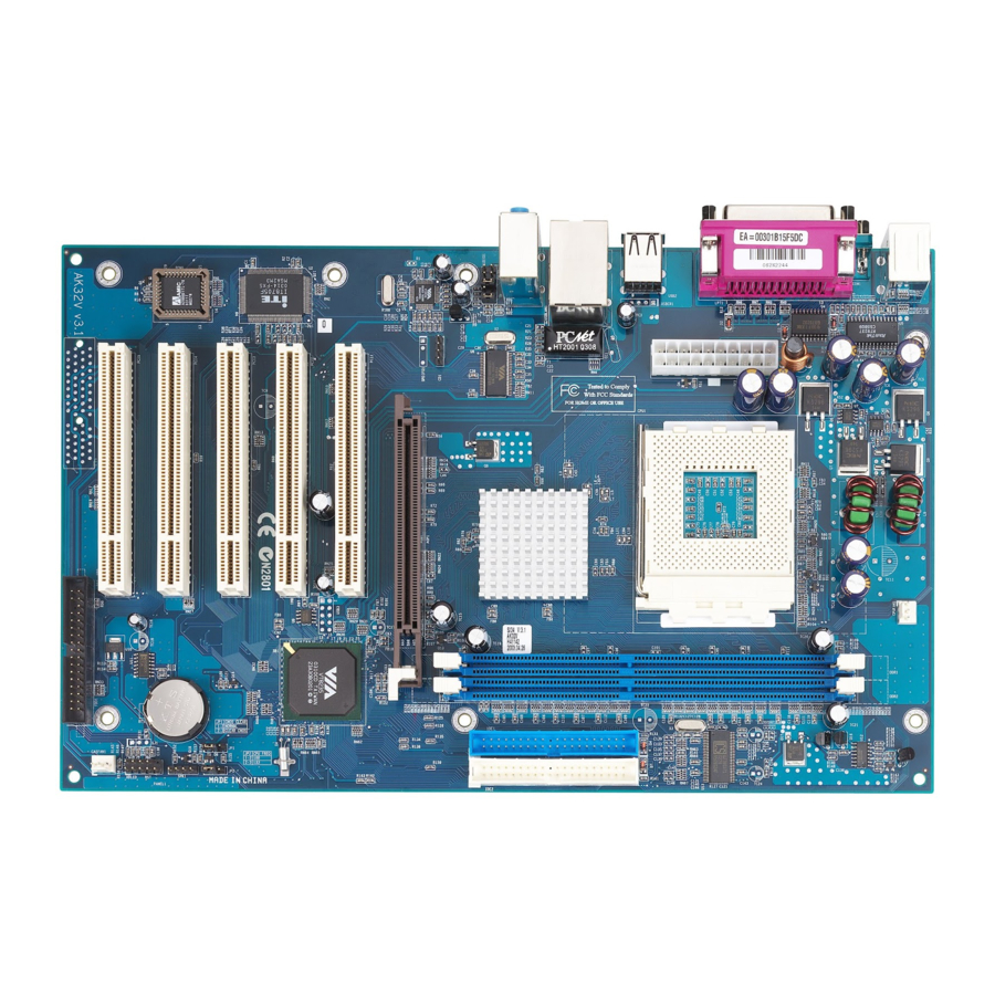
Add-On Cards, Cables, please make sure to unplug the onboard power connector. This section outlines how to install and configure your AK32V/AK32VN mainboard. Refer to the following mainboard layout to help you identify various jumpers, connectors, slots, and ports. Then follow these steps to guide you through a quick and correct instal- lation of your system. -
Page 16: Step 1 Install The Cpu
Step 1 Install the CPU: 1. Locate the CPU ZIF (Zero Insertion Force) socket on the upper-right sector of your mainboard (between the back-panel connectors and the DIMM memory slots). 2. Pull the CPU ZIF socket lever slightly sideways away from the socket to unlock the lever, and then bring it to an upwardly vertical position. -
Page 17: Step 2 Set Jumpers
Step 2. Set Jumpers This mainboard is jumperless! The default jumper settings have been set for the common usage standard of this mainboard. Therefore, you do not need to reset the jumpers unless you require special adjustments as in any of the following cases: 1. -
Page 18: Step 4 Install Internal Peripherals In System Case
Step 4 Install Internal Peripherals in System Case Before you install and connect the mainboard into your system case, we recommend that you first assemble all the internal peripheral devices into the computer housing, including but not limited to the hard disk drive (IDE /HDD), floppy disk drive (FDD), CD-ROM drive, and ATX power supply unit. -
Page 19: Step 5 Mount The Mainboard On The Computer Chassis
Step 5 Mount the Mainboard on the Computer Chassis 1. You may find that there are a lot of different mounting hole positions both on your computer chassis and on the mainboard. To choose a correct mounting hole, the key point is to keep the back-panel of the mainboard in a close fit with your system case, as shown below. -
Page 20: Step 6 Connect Front-Panel Switches/Leds/Speaker/Usb
Step 6 Connect Front-Panel LEDs/Switch/USBs You can find there are several different cables already existing in the system case and originating from computer's front-panel devices (MSG LED, HDD LED, PWR BTN, RST switch, or USB devices etc.). These cables serve to connect the front-panel LEDs, switch, and USB connectors to mainboard's front-panel connector groups (PANEL1 and USB3), as shown below. -
Page 21: Step 7 Connect Ide & Floppy Disk Drives
Step 7 Connect IDE and Floppy Disk Drives 1. IDE cable connectors IDE2 IDE1 2. Floppy cable connector FDD1 Step 8 Connect Other Internal Peripherals 1. CD-IN (CD1) - 17 -... -
Page 22: Step 9 Connect Power Supply
2. Internal Speaker Header (SPK1) 3. Front-panel Audio Header (AUDIO1) AUDIO1 Step 9 Connect the Power Supply 1. System power connector (ATX1) - 18 -... -
Page 23: Step 10 Install Add-On Cards In Expansion Slots
Step 10 Install Add-on Cards in Expansion Slots 1. AGP Card 2. PCI Card - 19 -... -
Page 24: Step 11 Connect External Peripherals To Back-Panel
Step 11 Connect External Peripherals to Back-Panel You are now ready to put the computer case back together and get on to the external peripherals connections to your system's back-panel. USB2 USBLAN1 PS/2 Mouse Port PS/2 Keyboard Port Parallel port COM1 Port LAN Port (AK32VN only) USB Ports... -
Page 25: Step 12 First Time System Boot Up
Step 12 First Time System Boot Up To assure the completeness and correctness of your system installation, you may check the above installation steps once again before you boot up your system for the first time. 1. Insert a bootable system floppy disk (DOS 6.2x, Windows 95/98/NT, or others) which contains FDISK and FORMAT utilities into the FDD. -
Page 26: Step 13 Install Driver & Software Components
2000/ME/XP/NT operating systems only. Make sure your operating system is already installed before running the drivers installation CD-ROM programs. 1. Insert the AK32V/AK32VN bundled CD-ROM into your CD-ROM drive. The autorun program will display the drivers main installation window on screen. -
Page 27: Jumper Settings
3.2 Jumper Settings Several hardware settings are made through the use of jumper caps to con- nect jumper pins to the mainboard. Pin #1 could be located at any corner of each jumper; you just find a location marked with a while right angle, which stands for pin1#. -
Page 28: Jumper & Connector Guide
Jumper & Connector Guide Use the mainboard layout on page 11 to locate CPU socket, memory slots, expansion slots, jumpers and connectors on the mainboard during installation. The following list will help you identify jumpers, slots, and connectors along with their assigned functions: B2~B3 B4~B5 B6~B8... -
Page 29: Jumpers
Jumpers : Clear CMOS : CPU frequency selection Back-Panel Connectors : PS/2 Keyboard Port : PS/2 Mouse Port LPT1 : Parallel Port (DB25 female) COM1 : Serial Port (DB9 male) USB1/2 : 4 USB (Universal Serial Bus) Ports : 10/100 base-TLAN Port (AK32VN only) LINE-OUT : Line-Out Port LINE-IN... -
Page 30: Clear Cmos Setting (Jp1)
Jumpers Clear CMOS Setting (JP1) JP1 is used to clear CMOS data. Clearing CMOS will result in the perma- nently erasing previous system configuration settings and the restoring original(factory-set) system settings. Pin 1-2 (Default) Pin 2-3 (Clear CMOS) Step 1. Turn off the system power (PC-> Off). Step 2. -
Page 31: Back-Panel Connectors Ps/2 Keyboard & Ps/2 Mouse Connectors
Back-Panel Connectors PS/2 Keyboard & PS/2 Mouse Connectors Two 6-pin female PS/2 keyboard & Mouse connectors are located at the rear panel PS/2 Mouse of mainboard. Depending on the com- puter housing you use (desktop or tower), the PS/2 Mouse connector is situated at the top of the PS/2 Keyboard connector when the mainboard is laid into a desk- PS/2 keyboard... -
Page 32: Lan Port Connector (Ak32Vn Only)
LAN Port Connector (AK32VN only) This mainboard can accommodate LAN Port one device on LAN. Attach a RJ45 cable to the LAN port at the back-panel of your computer. Line-in Port Line-In Line-In is a stereo line-level input port that accepts a 1/8-inch TRS stereo plug. -
Page 33: Front-Panel Connectors Atx Power On/Off Switch Connector (Pwr)
Front-Panel Connectors ATX Power On/Off Switch Connector (PWR) The Power On/Off Switch is a momentary type switch used for turning on or off the system ATX power supply. Attach the connector cable from the Power Switch to the 2-pin (PWR) header on the mainboard. Front Panel PANEL1 Note : Please notice all the LED connectors are directional. -
Page 34: Msg Led Connector (Msgled)
MSG LED Connector (MSGLED) Connecting MSG LED a single- or dual-color, front panel mounted LED pro- vides power on/off, sleep and message waiting indication. Front Panel PANEL1 Note : Please notice all the LED connectors are directional. If your chassis’s LED does not light up during running, please change it to an opposite direction. -
Page 35: Front-Panel Audio Header (Audio1)
Front-Panel Audio Header (AUDIO1) This header allows users to install an auxiliary Front-Oriented Audio port for easier access. Either the Line-Out port connector on back-panel or Front- Panel Audio header is available at the same time. If you would like to use this header on front-panel, please remove all jumpers from the Audio header and install your special extra audio cable instead. -
Page 36: Internal Peripherals Connectors
Internal Peripherals Connectors Enhanced IDE Ports and Floppy Connector The AK32V/AK32VN mainboard features two 40-pin dual-channel IDE device connectors (IDE1/IDE2) providing support to up to four IDE devices, such as CD-ROM and Hard Disk Drives (H.D.D.). This mainboard also includes one 34-pin floppy disk controller (FDC) to accommodate the Floppy Disk Drive (F.D.D.). -
Page 37: Other Connectors Atx Power Supply Connector (Atx1)
Other Connectors ATX Power Supply Connector (ATX1) Locate the 20-pin male header ATX power connector (ATX1) on your mainboard. Plug the power cable from the ATX power supply unit directly into ATX1 ATX power supply connector. Note 1: The ATX power connector is directional and will not go in unless the guides match perfectly making sure that pin#1 is properly positioned. -
Page 38: Cooling Fan Connectors - Cpu Fan1, Casfan1
Cooling Fan Connectors - CPUFAN1 & CASFAN1 The mainboard provides two onboard 12V cooling fan power connectors to support CPU (CPUFAN1), and System (CASFAN1) cooling fans. +12V SENSE CPUFAN1 Note: Both cable wiring and type of plug may vary, which depends on the fan maker. -
Page 39: Speaker Connector (Spk1)
Speaker connector (SPK1) Attach the PC speaker cable from the case to the 4-pin speaker connector (SPK1). Pin Assignments: 1=Signal 2=NA 3=GND 4=VCC - 35 -... -
Page 40: System Memory Configuration
3.3 System Memory Configuration AK32V/AK32VN mainboard has two 184-pin DIMM slots that allow you to install from 64MB up to 1GB of system memory. Each 184-pin DIMM (Dual In-line Memory Module) Slot can accommodate 128MB, 256MB, 512MB, and 1G of PC1600/PC2100 compliant 2.5V single (1 Bank) or double (2 Bank) side 64-bit wide data path DDR SDRAM mod- ules. -
Page 41: Software Utility
4 SOFTWARE UTILITY 4.1 Mainboard CD Overview Note: The CD contents attached in AK32V/AK32VN mainboard are subject to change without notice. To start your mainboard CD disc, just insert it into your CD-ROM drive and the CD AutoRun screen should appear. If the AutoRun screen does not appear, double click or run D:\Autorun.exe (assuming that your CD-ROM... -
Page 42: Install Mainboard Software
Autorun icon in My Computer to bring up Shuttle Mainboard Software Setup screen. Select using your pointing device (e.g. mouse) on the "Install Mainboard AK32V Driver" or "Install Mainboard AK32VN Driver" bar to run into sub-menu. The Mainboard AK32V Driver include: [4.2.A]... -
Page 43: A Install Via 4In1 Driver
4.2.A Install VIA 4in1 Driver Select using your pointing device (e.g. mouse) on the “Install VIA 4in1 Driver" bar to install VIA 4in1 Driver. AK32V AK32VN Once you made your selection, a Setup window run the installation automatically. When the copying files is done, make sure you reboot the system to take the installation effect. -
Page 44: B Install Via Lan Driver (Ak32Vn Only)
4.2.B Install VIA LAN Driver (AK32VN only) Select using your pointing device (e.g. mouse) on the “Install VIA LAN Driver"” bar to install VIA LAN driver. AK32VN Once you made your selection, a Setup window run the installation automatically. When the copying files is done, make sure you reboot the system to take the installation effect. -
Page 45: C Install Via Audio Driver
4.2.C Install VIA Audio Driver Select using your pointing device (e.g. mouse) on the “Install VIA Audio Driver"” bar to install AC'97 Audio driver. AK32V AK32VN Once you made your selection, a Setup window run the installation automatically. When the copying files is done, make sure you reboot the system to take the installation effect. -
Page 46: D Install Via Usb2.0 Driver
4.2.D Install VIA USB2.0 Driver Select using your pointing device (e.g. mouse) on the “Install VIA USB2.0 Driver"” bar to install VIA USB2.0 driver. AK32V AK32VN Once you made your selection, a Setup window run the installation automatically. When the copying files is done, make sure you reboot the system to take the installation effect. -
Page 47: View The User's Manual
Insert the attached CD into your CD-ROM drive and the CD AutoRun screen should appear. If the AutoRun screen does not appear, double click on AutoRun icon in My Computer to bring up Shuttle Mainboard Software Setup screen. Select using your pointing device (e.g. mouse) on the “Manual" bar. -
Page 48: Bios Setup
5 BIOS SETUP AK32V/AK32VN BIOS ROM has a built-in Setup program that allows users to modify the basic system configuration. This information is stored in battery- backed RAM so that it retains the Setup information even if the system power is turned off. -
Page 49: The Main Menu
Note: The content of this manual is subject to any change without notice in advance. 5.2 The Main Menu Once you enter the AwardBIOS(tm) CMOS Setup Utility, the Main Menu will appear on the screen. The Main Menu allows you to select from several setup functions and two exit choices. - Page 50 Integrated Peripherals Use this menu to specify your settings for integrated peripherals. Power Management Setup Use this menu to specify your settings for power management. PnP / PCI Configuration This entry appears if your system supports PnP / PCI. PC Health Status This entry shows the current system temperature, Voltage, and FAN speed.
-
Page 51: Standard Cmos Features
Standard CMOS Features The items in Standard CMOS Setup Menu are divided into 10 catego- ries. Each category includes no, one or more than one setup items. Use the arrow keys to highlight the item and then use the <PgUp> or <PgDn>... - Page 52 IDE Secondary Slave Options are in its sub menu. Press <Enter> to enter the sub-menu of detailed options. Drive A/Drive B Select the type of floppy disk drive installed in your system. Ø The choice: None, 360K, 5.25 in, 1.2M, 5.25 in, 720K, 3.5 in, 1.44M, 3.5 in, or 2.88M, 3.5 in Video Select the default video device.
- Page 53 ****************************************************** IDE Adapters The IDE adapters control the hard disk drive. Use a separate sub-menu to configure each hard disk drive. IDE HDD Auto-Detection Press <Enter> to auto-detect HDD on this channel. If detection is successful, it fills the remaining fields on this menu. Ø...
- Page 54 Precomp Warning: Setting a value of 65535 means no hard disk. Ø Min = 0, Max = 65535 Landing zone Set the Landing zone size. Ø Min = 0, Max = 65535 Sector Number of sector per track. Ø Min = 0, Max = 255 ****************************************************** - 50 -...
-
Page 55: Advanced Bios Features
Advanced BIOS Features This section allows you to configure your system for basic operation. You have the opportunity to select the system's default speed, boot-up sequence, keyboard operation, shadowing, and security. CPU Internal Cache All processors that can be installed in this mainboard use internal level1 (L1) cache memory to improve performance. - Page 56 First/Second/Third Boot Device The BIOS attempts to load the operating system from the devices in the sequence selected in these items. Ø The Choice: Floppy, LS120, HDD-0, SCSI, CDROM, HDD-1, HDD-2, HDD-3, ZIP100, LAN, or Disabled. Boot Other Device Select Your Boot Device Priority. Ø...
- Page 57 Typematic Rate (Chars/Sec) This item sets how many times the keystroke will be repented in a second when you hold the key down. Ø The choice: 6, 8, 10, 12, 15, 20, 24, or 30. Typematic Delay (Msec) Sets the delay time after the key is held down before it begins to repeat the keystroke.
- Page 58 Video BIOS Shadow Determines whether video BIOS will be copied to RAM. However, it is optional depending on chipset design. Video Shadow will increase the video speed. Ø The choice: Enabled or Disabled. Small Logo(EPA) Show This item allows you to enable/disable the EPA Logo. Ø...
-
Page 59: Advanced Chipset Features
Advanced Chipset Features This section allows you to configure the system based on the specific features of the installed chipset. This chipset manages bus speeds and access to system memory resources, such as DRAM and the external cache. It also coordinates communications between the conventional ISA bus and the PCI bus. - Page 60 DRAM Timing This item allows you to select the value in this field, depending on whether the board using which kind of DDR DRAM. Ø The Choice: By SPD or Manual. The following five items will become selectable if you choose "Manual"...
- Page 61 AGP Mode This item allows you to select the AGP Mode. Ø The Choice: 1x, 2x, or 4x. AGP Driving Control This item enables the system to automatically select its output buffer drive strength or make it manually selectable by an end user. Ø...
- Page 62 PCI Delay Transaction The chipset has an embedded 32-bit posted write buffer to support delay transactions cycles. Select Enabled to support compliance with PCI specification version 2.1. Ø The Choice: Enabled or Disabled. Memory Hole In order to improve performance, some space in memory can be reserved for ISA cards.
-
Page 63: Integrated Peripherals
Integrated Peripherals USB 2.0 Support The item allows you to enable/disable the USB2.0 support. Ø The Choice: Disabled or Enabled. VIA OnChip IDE Device Options are in its sub-menu. Press <Enter> to enter the sub-menu of detailed options. OnChip IDE Channel0 The chipset contains a PCI IDE interface with support to two IDE chan- nels. - Page 64 IDE Prefetch Mode The onboard IDE drive interfaces support IDE prefetching for faster drive access. If you install a primary and/or secondary add-on IDE interface, set this field to Disabled if the interface does not support prefetching. Ø The choice: Enabled or Disabled. Primary/Secondary Master/Slave PIO The four IDE PIO (Programmed Input/Output) fields let you set a PIO mode (0-4) for each of the four IDE devices that the onboard IDE inter-...
- Page 65 Super IO Device Options are in its sub-menu. Press <Enter> to enter the sub-menu of detailed options. Onboard FDC Controller Select Enabled if your system has a floppy disk controller (FDC) installed on the system board and you want to use it. If you install add-on FDC or the system has no floppy drive, select Disabled in this field.
- Page 66 OnChip USB Controller This should be enabled if your system has a USB installed on the system board and you want to use it. Even when on chip USB so equipped, if you add a higher performance controller, you will need to disable this feature.
-
Page 67: Power Management Setup
Power Management Setup The Power Management Setup allows you to configure your system to most effectively saving energy while operating in a manner consistent with your own style of computer use. ACPI Function This item always enable the Advanced Configuration and Power Inter- face. - Page 68 HDD Power Down When this item enabled and after the set up time of system inactiv- ity, the hard disk drive will be powered down while all other de- vices remain active. Ø The choice: Disabled or 1 Min~15 Min. Suspend Mode When this item enabled and after the set up time of system inactivity, all devices except the CPU will be shut off.
- Page 69 State After Power Failure This allows you to set whether you want your system to reboot after power has been interrupted. Ø The choice:On, Off or Fomer State . IRQ/Event Activity Detect Options are in its sub-menu. Press <Enter> to enter the sub-menu of detailed options. When this item enabled, you can set VGA to awaken the system.
- Page 70 Data (of Month) This item selects the alarm date. Ø Key in a DEC number:Min=0, Max=31. Resume Time (hh:mm:ss) This item selects the alarm Time. [hh] Ø Key in a DEC number:Min=0, Max=23. [mm/ss] Ø Key in a DEC number:Min=0, Max=59. IRQs Activity Monitoring Primary INTR Press Enter to on/off the wake up ability of a specified IRQ.
-
Page 71: Pnp/Pci Configuration
PnP/PCI Configuration This section describes the configuration of PCI bus system. PCI or Personal Computer Interconnection is a system which allows I/O devices to operate at the speed CPU itself keeps when CPU communicating with its own special components. This section covers some very technical items, and it is strongly recommended that only experienced users should make any changes to the default settings. - Page 72 IRQ Resources When resources are controlled manually, assign each system interrupt a type, depending on the type of device using the interrupt. IRQ3/4/5/7/9/10/11/12/14/15 assigned This item allows you to determine the IRQ assigned to the ISA bus and is not available to any PCI slot. Legacy ISA for devices is compliant with the original PC AT bus specification;...
-
Page 73: Pc Health Status
PC Health Status Target Temperature This item is for CPU Throttling switch. When the CPU reached it's target temperature, the CPU Throttling will be activated. Enabling this item will protect your CPU not to overheat, but it will reduce the CPU perfor- mance. -
Page 74: Frequency/Voltage Control
Frequency/Voltage Control CPU Voltage Regulator This item show the voltage set after fine tuning. Ø The choice:Normal, +25mV, +50mV or +75mV. Auto Detect DIMM/PCI Clk This item allows you to enable/disable auto detection DIMM/PCI Clock. Ø The choice: Enabled or Disabled. Spread Spectrum This item allows you to enable/disable the spread spectrum. -
Page 75: Load Fail-Safe Defaults
Load Fail-Safe Defaults When you press <Enter> on this item, you will get a confirmation dialog box with a message similar to: Load Fail-Safe Defaults (Y/N) ? N Pressing 'Y' loads the BIOS default values for the most stable, minimal performance system operations. Load Optimized Defaults When you press <Enter>... -
Page 76: Set Supervisor Password
Supervisor/User Password Setting You can set either supervisor or user password, or both of them. The differences between them are: Supervisor Password and User Password The options on the Password screen menu make it possible to restrict access to the Setup program by enabling you to set passwords for two different access modes: Supervisor mode and User mode. - Page 77 Password Disable If you select System at Security Option of BIOS Features Setup Menu, you will be prompted in entering the password whenever the system is rebooted or you try to enter Setup. If you select Setup at Security Op- tion of BIOS Features Setup Menu, you will be prompted only when you try to enter Setup.
Need help?
Do you have a question about the AK32V and is the answer not in the manual?
Questions and answers