Table of Contents
Advertisement
Quick Links
Advertisement
Table of Contents

Related Manuals for Shuttle AB45


Summary of Contents for Shuttle AB45
- Page 1 AB45 Pentium 4 Processor Based DDR MAIN BOARD User's Manual...
- Page 2 The information contained in this manual is provided for general use by the customers. Trademarks Shuttle is a registered trademark of Shuttle Inc. Intel, Pentium is a registered trademarks of Intel Corporation. PS/2 is a registered trademark of IBM Corporation.
-
Page 3: Table Of Contents
2.1 SPECIFICATIONS ..................8 3 HARDWARE INSTALLATION ............11 3.1 STEP BY STEP INSTALLATION ..............11 Accessories of AB45 ................11 STEP 1 Install the CPU ................. 12 STEP 2 Set Jumpers ................14 STEP 3 Install DDR SDRAM System Memory ........14 STEP 4 Install Peripherals in System Case ........... - Page 4 3.2 JUMPER SETTINGS ................. 25 JUMPERS & CONNECTORS GUIDE ............ 26 Jumpers Clear CMOS Setting (JP2) ..............29 Back-Panel Connectors PS/2 Keyboard & PS/2 Mouse Connectors ..........30 USB1/USB2 Port Connectors ..............30 COM1/2 Port Connectors ..............30 Parallel Port Connector ................30 Line-Out (6-Channel Front-Out) Port Connector ........
- Page 5 IR Header(JP9)..................39 Audio CD-IN Connector (CN4/CN12) (Black/Write) ........ 40 Audio Bass/Center-Out Header (CN13) ..........40 Audio Auxiliary-IN Connector (CN11) (White) ......... 40 Front-Panel Microphone and Line_out Header (JP10) ......41 SPDIF Ext. Header (JP14)..............42 Extended USB Header (JP7/8) .............. 42 3.3 SYSTEM MEMORY CONFIGURATION .............
- Page 6 PC HEALTH STATUS ................75 FREQUENCY/VOLTAGE CONTROL ............76 LOAD FAIL-SAFE DEFAULTS ..............77 LOAD OPTIMIZED DEFAULTS ..............77 SET SUPERVISOR PASSWORD ............. 78 SET USER PASSWORD ................78 SAVE & EXIT SETUP ................79 EXIT WITHOUT SAVING ................79 - 4 -...
-
Page 7: What's In The Manual
WHAT S IN THE MANUAL Quick Reference Hardware Installation >> Step-by-Step ..........Page 11 Jumper Settings >> A Closer Look ............Page 25 Drivers/Software Utilities >> How to Install ......... Page 44 BIOS Setup >> How to Configure ............Page 50 About This Manual For First-Time DIY System Builder ............ -
Page 8: Introduction
Shuttle AB45 mainboard. Experienced DIY User Congratulate on your purchase of the Shuttle AB45 mainboard. You will find that installing your new Shuttle AB45 mainboard is just easy. Bundled with an array of onboard functions, the highly-integrated AB45 mainboard pro- vides you with a total solution to build the most stable and reliable system. -
Page 9: Item Checklist
1.2 Item Checklist: Check all items with you AB45 mainboard to make sure nothing is miss- ing. The complete package should include: One piece of Shuttle AB45 Mainboard V C C C N 6 A TX P WR One piece of Audio Cable (Central/Bass Channel) -
Page 10: Features
2 FEATURES AB45 mainboard is carefully designed for the demanding PC user who wants high performance and maximum intelligent features in a compact package. 2.1 Specifications - CPU Support Intel Pentium 4, 478-pin processors with 400/533 MHz FSB. - Chipset Features Intel 82845E N.B. - Page 11 Ø 1* PS/2 mouse connector. Ø 1* PS/2 keyboard connector. Ø 2* DB9 Serial connectors 16550 UART compatible. Ø 1* Infrared communication port. (Serial port COM2 can also be redirected to an external IrDA Adapter for wireless connection.) Ø 1* DB25 Parallel port supports Standard Parallel Port and Bi-directional (SPP), Enhanced Parallel Port (EPP), and Extended Capabilities Port (ECP) data transmission schemes.
- Page 12 - ATX Form Factor System board conforms to ATX specification. Board dimension: 305mm* 190mm. - Advanced Features Ø Low EMI - Built in spread spectrum and automatic clock shut-off of unused PCI/DDR-SDRAMS slots to reduce EMI. Ø Dual Function Power Button - The system can be in one of two states, one is Suspend mode and the other is Soft-Off mode.
-
Page 13: Hardware Installation
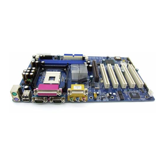
Then follow these steps designed to guide you through a quick and correct installation of your system. 3.1 Step-by-Step Installation Accessories Of AB45 ATX 12V Power Connector SOCKET 478 INTEL 82845E Chipset... -
Page 14: Step 1 Install The Cpu
Step 1 CPU Installation: This mainboard supports Intel Pentium 4 , Socket 478 series CPU. Please follow the step as below to finish CPU installation. Be careful of CPU orientation when you plug it into CPU socket. 1. Pull up the CPU socket lever and up to 90-degree angle. CPU socket lever up to 90 degree 2. - Page 15 3. Press down the CPU socket lever and finish CPU installation. Note: Note: Note: Note: Note: If you do not match the CPU socket Pin 1 and CPU cut edge well, it may damage the CPU. 4. The Intel Pentium 4 /Celeron processor requires a set of heatsink/fan to en sure proper cooling of the processor.
-
Page 16: Step 2 Set Jumpers
Step 2. Set Jumpers This mainboard is jumperless! The default jumper settings have been set for the common usage standard of this mainboard. Therefore, you do not need to reset the jumpers unless you require special adjustments as any of the following cases: 1. -
Page 17: Step 4 Install Peripherals In System Case
Step 4 Install Internal Peripherals in System Case Before you install and connect the mainboard into your system case, we recommend that you first assemble all the internal peripheral devices into the computer housing, including but not limited to the hard disk drive (IDE/ HDD), floppy disk drive (FDD), CD-ROM drive, and ATX power supply unit. -
Page 18: Step 5 Mount The Mainboard On The Computer Chassis
Step 5 Mount the Mainboard on the Computer Chassis 1. You may find that there are a lot of different mounting hole positions both on your computer chassis and on the mainboard. To choose correct mounting holes, the key point is to keep the back-panel of the mainboard in a close fit with your system case, as shown below. -
Page 19: Step 6 Connect Front Panel Switches/Leds/Speaker/Usb
Step 6 Connect Front Panel Switches/LEDs/Speaker/USB You can find there are several different cables already existing in the system case and originating from the computer's front-panel devices (HDD LED, Power LED, Reset Switch, PC Speaker, or USB devices etc.) These cables serve to connect the front-panel switches, LEDs, and USB connectors to the mainboard's front-panel connectors group (JP11), as shown below. - Page 20 Green Power Power 3. Power LED (PLED) JP11 EPMI Speaker Reset 4. HDD-LED (HLED) Green Power Power JP11 Speaker EPMI Reset 5. Hardware Reset Switch Button (RST) Green Power Power JP11 Speaker EPMI Reset 6. System Management Interface Button (EPMI) Power Green Power...
-
Page 21: Step 7 Connect Ide, And Floppy Disk Drives
9. Extended USB Header USB port 5&6 USB port 3&4 Step 7 Connect IDE, and Floppy Disk Drives 1. IDE cable connector IDE2 IDE1 2. Floppy cable connector - 19 -... -
Page 22: Step 8 Connect Other Internal Peripherals
Step 8 Connect Other Internal Peripherals 1. CD-IN , Auxiliary-IN, Bass/Center-Out connectors CN12 CD-IN CD-IN CN11 CN13 AUX_IN BASS 2. IR header Step 9 Connect the Power Supply 1. System power connector CN 14 ATX12V - 20 -... -
Page 23: Step 10 Install Add-On Cards In Expansion Slots
Step 10 Install Add-on Cards in Expansion Slots 1. Accelerated Graphics Port (AGP) Card 2. PCI Card - 21 -... -
Page 24: Step 11 Connect External Peripherals To Back Panel
Step 11 Connect External Peripherals to Back-Panel You are now ready to put the computer case back together and get on to the external peripherals connections to your system's back-panel. KB _MS US B COM1 C O M 2 P R T A U D I O 1. - Page 25 4. Parallel Port foxcon n Parallel Port 5. MIDI/GAME Port MIDI/GAME Port 6. Audio Line-Out (6-Channel Front-Out) /Line-In (6-Channel Rear-Out) / Mic-In Ports Line-Out Port Mic-In Port Line-In Port (6 ChannelFront-Out) (6 Channel Rear-Our) - 23 -...
-
Page 26: Step 12 Install Drivers & Software Components
2000/ME/NT/XP operating systems only. Make sure your operating system is already installed before running the drivers installation CD-ROM programs. 1. Insert the AB45 bundled CD-ROM into your CD-ROM drive. The auto-run program will display the drivers main installation window on screen. -
Page 27: Jumper Settings
3.2 Jumper Settings Several hardware settings are made through the use of mini jumpers to con- nect jumper pins on the mainboard. Pin #1 could be located at any corner of each jumper, you just find the location with a white right angle which stands for pin 1#. -
Page 28: Jumpers & Connectors Guide
Jumpers & Connectors Guide Use the mainboard layout on page 11 to locate CPU socket, memory banks, expansion slots, jumpers and connectors on the mainboard during the instal- lation. The following list will help you to identify jumpers, slots, and connec- tors along with their assigned functions: B3~B4 B5~B8... - Page 29 Jumpers : Clear CMOS setting Back Panel Connectors : PS/2 keyboard port : PS/2 mouse port : 2 USB (Universal Serial Bus) ports COM1/2 : Serial ports 1/2 (DB9 male) PRINTER : Parallel port (DB25 female) LINE_OUT : Line-Out (6-Channel Front-Out) port LINE_IN : Line-In (6-Channel Rear-Out) port MIC_IN...
- Page 30 Other Connectors : ATX power connector FAN1 : CPU fan connector FAN2 : AGP fan connector FAN3 : Chassis fan connector : Wake-On-LAN connector : IR header CN4/CN12 : CD_IN connector CN13 : Bass/Center_Out header CN11 : Auxiliary_IN connector JP10 : Front-Panel Microphone and Line-Out Connector JP14 : SPDIF Ext connector...
-
Page 31: Jumpers
Jumpers Clear CMOS Setting (JP2) JP2 is used to clear CMOS data. Clearing CMOS will result in the perma- nently erasing previous system configuration settings and the restoring origi- nal (factory-set) system settings. Pin 1-2 (Default) Pin 2-3 (Clear CMOS) Step 1. -
Page 32: Back-Panel Connectors
Back-Panel Connectors PS/2 Keyboard & PS/2 Mouse Connectors Two 6-pin female PS/2 keyboard & Mouse connectors are located at the rear panel of the mainboard. Depending on the com- PS/2 Mouse puter housing you use (desktop or tower), the PS/2 Mouse connector is situated at the top of the PS/2 Keyboard connector when the mainboard is laid into a desktop, as op- posed to a tower where the PS/2 Mouse... -
Page 33: Line-Out (6-Channel Front-Out) Port Connector
Line-Out (6-Channel Front-Out) Port Connector Line-Out is a stereo output port through which the combined signal of all internal and external audio sources on the board is output. It can be connected to 1/8-inch TRS stereo headphones or to amplified speakers Line-Out (6-Channel Front-Out) Line-In (6-Channel Rear-Out) Port Connector... -
Page 34: Front-Panel Connectors Green Led Connector (Green Led)
Front-Panel Connectors Green LED Connector (Green LED) The Green LED (Green LED) indicates that the system is currently in one of the power saving mode (Doze/Standby/Suspend). When the system resumes to normal operation mode, the Green LED will go off, Attach a 2-pin Green LED cable to Green LED header. -
Page 35: Atx Power On/Off Switch Connector (Power On)
ATX Power On/Off Switch Connector (Power ON) The Power On/Off Switch is a momentary type switch used for turning on or off the system ATX power supply. Attach the connector cable from the Power Switch to the 2-pin (PWON) header on the mainboard. Power Green Power... -
Page 36: Power Led Connector(Power Led)
Power LED Connector (Power LED) Attach the 3-pin Power LED connector cable from the housing front panel to the (Power LED) header on the mainboard. The power LED stays light while the system is on. Power Green Power JP11 EPMI Speaker Reset EPMI Connector (EPMI) -
Page 37: Speaker Connector (Speaker)
Speaker Connector (Speaker) Attach the PC speaker cable from the case to the 4-pin speaker connector (Speaker). Green Power Power JP11 EPMI Speaker Reset - 35 -... -
Page 38: Internal Peripherals Connectors
Internal Peripherals Connectors Enhanced IDE , and Floppy Connectors The mainboard features two 40-pin dual-channel IDE device connectors (IDE1/IDE2) providing support for up to four IDE devices, such as CD-ROM and Hard Disk Drives (H.D.D.) This mainboard also includes one 34-pin floppy disk controller (FDC) to accommodate the Floppy Disk Drive (FDD). -
Page 39: Other Connectors
Other Connectors ATX Power Supply Connector (CN6/CN14) This motherboard uses 20-pin Pentium 4 standard ATX power header, CN6 and comes with another two headers. One is ATX12V with 2*2-pin +12 VPC ATX power supply header. Please make sure you plug in the right direction. CN14 CN 14 ATX12V... -
Page 40: Wake-On Lan Connector (Jp6)
CPU, AGP, Chipset and Chassis Fan connectors - FAN1/2/3 The mainboard provides three onboard 12V cooling fan power connectors to support CPU (FAN1), AGP (FAN2), Chassis (FAN3) cooling fans. Note: Note: Note: Note: Note: Both cable wiring and type of plug may vary , which depends on the fan maker. -
Page 41: Ir Header(Jp9)
IR Header (JP9) If you have an Infrared device, this mainboard can implement IR transfer function. To enable the IR transfer function, follow these steps: Pins Assignment: IR 1 1=NC 2=KEY 3=+5V 4=GND 5=IRTX 6=IRRX Note: Note: Note: Before connect your IR device, please be sure each IR on board Note: Note: pin allocation is matchable with the pin of the IR device. -
Page 42: Audio Cd-In Connector (Cn4/Cn12) (Black/Write)
Audio CD_IN Connector (CN4/CN12) (Black/Write) Port CN4/CN12 is used to attach an audio connector cable from the CD- ROM drive. CN12 CD-IN CD-IN Pin Assignments: 1=CD-L 2=CD-GND 3=CD-GND 4=CD-R Audio Bass/Center_Out Header (CN13) CN13 header can be used to connect the cable which attached to bass/eenter amplified speakers. -
Page 43: Front-Panel Microphone And Line_Out Header (Jp10)
Front-Panel Microphone and Line_out Header (JP10) This header allows users to install auxiliary front-oriented microphone and line-out ports for easier access. Either the Mic and Line_out connector on back- panel or JP10 header are available at the same time. If you would like to use this JP10 header on front-panel, please remove all jumpers from JP10 and install your special Extra Mic / Line_out cable instead. -
Page 44: Spdif Ext. Header (Jp14)
SPDIF Ext Headers (JP14) Port JP14 can be used to connect special device. JP14 SPDIF Pin Assignments: 1=+12V 2=N/A 3=N/A 4=SPDIF-OUT 5=SPDIF-IN 1 6=GND 7=SPDIF-IN 2 8=SPGPIO (optional) 9=KEY 10=GND Extended USB Header (JP7/8) The headers are used to connect the cable attached to USB connectors which are mounted on front panel or back panel. -
Page 45: System Memory Configuration
3.3 System Memory Configuration The AB45 mainboard has two 184-pin DIMM banks that allow you to install from 128MB up to 1GB of system memory. Each 184-pin 184-pin 184-pin DIMM (Dual In-line Memory Module) bank can accommo- 184-pin 184-pin date 128MB, 256MB, 512MB, and 1GB of PC1600/PC2100 compliant 2.5V single or double side unbuffered with or without ECC DDR SDRAM... -
Page 46: Software Utility
4 SOFTWARE UTILITY 4.1 Mainboard CD Overview Note: The CD contents attached in AB45 mainboard are subject to change without notice. To start your mainboard CD disc, just insert it into your CD-ROM drive and the CD AutoRun screen should appear. If the AutoRun screen does not appear, double click or run D:\Autorun.exe (assuming that your CD-... -
Page 47: Install Mainboard Software
Insert the attached CD into your CD-ROM drive and the CD AutoRun screen should appear. If the AutoRun screen does not appear, double click on Autorun icon in My Computer to bring up Shuttle Mainboard Software Setup screen. Use your pointing device (e.g.mouse) to select "Install Intel Chipset Driver"... -
Page 48: Install Ide Driver
4.3 Install IDE Driver This driver may do bad effect on some model or brand of IDE HDD devices. Hereby, we won't suggest users to install it cause it might crash your HDD data. However, if you are very sure that the driver matches your IDE HDD, please follow below indication to complete setup. -
Page 49: Install Audio Driver
4.4 Install Audio Driver Select using your pointing device (e.g. mouse) on the “Install Audio Driver" bar to install audio driver. Once you made your selection, a Setup window run the installation automatically. When the copying files is done, make sure you reboot the system to take the installation effect. -
Page 50: Install Usb 2.0 Driver
4.5 Install USB 2.0 Driver Select using your pointing device (e.g. mouse) on the “Install USB 2.0 Driver" bar to install audio driver. Once you made your selection, a Setup window run the installation automatically. When the copying files is done, make sure you reboot the system to take the installation effect. -
Page 51: View The User's Manual
Insert the attached CD into your CD-ROM drive and the CD AutoRun screen should appear. If the AutoRun screen does not appear, double click on AutoRun icon in My Computer to bring up Shuttle Mainboard Software Setup screen. Select using your pointing device (e.g. mouse) on the “Manual" bar. -
Page 52: Bios Setup
5 BIOS SETUP AB45 BIOS ROM has a built-in Setup program that allows users to modify the basic system configuration. This information is stored in battery-backed RAM so that it retains the Setup information even if the system power is turned off. -
Page 53: The Main Menu
5.2 The Main Menu Once you enter the AwardBIOS(tm) CMOS Setup Utility, the Main Menu will appear on the screen. The Main Menu allows you to select from several setup functions and two exit choices. Use the arrow keys to select among the items and press <Enter> to accept and enter the sub-menu. - Page 54 PnP / PCI Configurations This entry appears if your system supports PnP / PCI. PC Health Status This entry shows the current system temperature, Voltage, and FAN speed. Frequency/Voltage Control Use this menu to specify your settings for frequency/voltage control. Load Fail-Safe Defaults Use this menu to load the BIOS default values for the minimal/stable performance of your system to operate.
-
Page 55: Standard Cmos Features
Standard CMOS Features The items in Standard CMOS Setup Menu are divided into 10 catego- ries. Each category includes no, one or more than one setup items. Use the arrow keys to highlight the item and then use the <PgUp> or <PgDn>... - Page 56 IDE Secondary Master IDE Secondary Master IDE Secondary Master IDE Secondary Master IDE Secondary Master Options are in its sub-menu. Press <Enter> to enter the sub-menu of detailed options. IDE Secondary Slave IDE Secondary Slave IDE Secondary Slave IDE Secondary Slave IDE Secondary Slave Options are in its sub menu.
- Page 57 ****************************************************** ****************************************************** ****************************************************** ****************************************************** ****************************************************** IDE Adapters The IDE adapters control the hard disk drive. Use a separate sub-menu to configure each hard disk drive. IDE HDD Auto-Detection IDE HDD Auto-Detection IDE HDD Auto-Detection IDE HDD Auto-Detection IDE HDD Auto-Detection Press <Enter>...
- Page 58 Precomp Precomp Precomp Precomp Precomp Warning: Setting a value of 65535 means no hard disk. Min = 0, Max = 65535 Landing zone Landing zone Landing zone Landing zone Landing zone Set the Landing zone size. Min = 0, Max = 65535 Sector Sector Sector...
-
Page 59: Advanced Bios Features
Advanced BIOS Features This section allows you to configure your system for basic operation. You have the opportunity to select the system's default speed, boot-up sequence, keyboard operation, shadowing, and security. BIOS Write Protect BIOS Write Protect BIOS Write Protect BIOS Write Protect BIOS Write Protect This item let you enable or disable the BIOS Write Protect. - Page 60 Quick Power On Self Test Quick Power On Self Test Quick Power On Self Test Quick Power On Self Test Quick Power On Self Test This item speeds up Power-On Self Test (POST) after you power on the computer. If it is set to enabled, BIOS will shorten or skip some check items during POST.
- Page 61 keyboard still provides this support, it is more common and much faster in setting to Fast for the system chipset to provide support for gate A20. Ø The choice: Normal, or Fast. Typematic Rate Setting Keystrokes repeat at a rate determined by the keyboard controller. When this controller enabled, the typematic rate and typematic delay can be selected.
- Page 62 MPS Version Control For OS MPS Version Control For OS MPS Version Control For OS MPS Version Control For OS MPS Version Control For OS Selects the operating system multiprocessor support version. The choice: 1.1 or 1.4 OS Select For DRAM > 64MB OS Select For DRAM >...
-
Page 63: Advanced Chipset Features
Advanced Chipset Features This section allows you to configure the system based on the specific features of the installed chipset. This chipset manages bus speeds and access to system memory resources, such as DRAM and the external cache. It also coordinates communications between the conventional ISA bus and the PCI bus. - Page 64 DRAM RAS# to CAS# Delay DRAM RAS# to CAS# Delay DRAM RAS# to CAS# Delay DRAM RAS# to CAS# Delay DRAM RAS# to CAS# Delay This field lets you insert a timing delay between the CAS and RAS strobe signals, and you can use it when DRAM is written to, read from, or refreshed.
- Page 65 The Choice: Enabled or Disabled. Memory Hole At 15M-16M Memory Hole At 15M-16M Memory Hole At 15M-16M Memory Hole At 15M-16M Memory Hole At 15M-16M You can reserve this area of system memory for ISA adapter ROM. When this area is reserved, it cannot be cached. The user information of peripherals that need to use this area of system memory usually discusses their memory requirements.
-
Page 66: Integrated Peripherals
Integrated Peripherals On-Chip Primary PCI IDE On-Chip Primary PCI IDE On-Chip Primary PCI IDE On-Chip Primary PCI IDE On-Chip Primary PCI IDE The integrated peripherals controller contains an IDE interface with support to two IDE channels. Select Enabled to activate each channel separately. - Page 67 IDE Primary Master/Slave UDMA IDE Primary Master/Slave UDMA IDE Primary Master/Slave UDMA IDE Primary Master/Slave UDMA IDE Primary Master/Slave UDMA Ultra DMA33/66/100 implementation is possible only if your IDE hard drive supports it and the operating environment includes a DMA driver (Windows 95 OSR2 or a third-party IDE bus master driver).
- Page 68 USB Keyboard Support USB Keyboard Support USB Keyboard Support USB Keyboard Support USB Keyboard Support Select Enabled if your system contains a Universal Serial Bus (USB) controller and you have a USB keyboard. The choice: Enabled or Disabled. USB Mouse Support USB Mouse Support USB Mouse Support USB Mouse Support...
- Page 69 Onboard FDC Controller Onboard FDC Controller Onboard FDC Controller Onboard FDC Controller Onboard FDC Controller This item specifices onboard floppy disk drive controller. This setting allows you to connect your floppy disk drives to the onboard floppy connector. Choose the "Disabled" settings if you have a separate control card.
- Page 70 Game Port Address Game Port Address Game Port Address Game Port Address Game Port Address This item selects Game Port Address. The choice: Disabled, 201, or 209. Midi Port Address Midi Port Address Midi Port Address Midi Port Address Midi Port Address This item selects Midi Port Address.
-
Page 71: Power Management Setup
Power Management Setup The Power Management Setup allows you to configure your system to most effectively saving energy while operating in a manner con- sistent with your own style of computer use. ACPI Function ACPI Function ACPI Function ACPI Function ACPI Function This item allows you to enable/disable the Advanced Configuration and Power Management (ACPI) - Page 72 Max Saving Max Saving Max Saving Max Saving Max Saving Maximum power management. Suspend Mode=1min. HDD Power Down=1min. User Define User Define User Define User Define User Define Allows you to set each mode individually. When this item not disabled, each of the ranges are from 1 min.
- Page 73 HDD Power Down HDD Power Down HDD Power Down HDD Power Down HDD Power Down When this item enabled and after the set up time of system inactiv- ity, the hard disk drive will be powered down while all other de- vices remain active.
- Page 74 Time (hh:mm:ss) Alarm Time (hh:mm:ss) Alarm Time (hh:mm:ss) Alarm Time (hh:mm:ss) Alarm Time (hh:mm:ss) Alarm This item selects the alarm Time. [hh] Key in a DEC number:Min=0, Max=23. [mm/ss] Key in a DEC number:Min=0, Max=59. *** Reload Global Timer Events *** *** Reload Global Timer Events *** *** Reload Global Timer Events *** *** Reload Global Timer Events ***...
-
Page 75: Pnp/Pci Configuration
PnP/PCI Configurations This section describes the configuration of PCI bus system. PCI or Personal Computer Interconnection is a system which allows I/O devices to operate at the speed CPU itself keeps when CPU communicating with its own special components. This section covers some very technical items, and it is strongly recommended that only experienced users should make any changes to the default settings. - Page 76 IRQ Resources IRQ Resources IRQ Resources IRQ Resources IRQ Resources When resources are controlled manually, assign each system interrupt a type, depending on the type of device using the interrupt. IRQ3/4/5/7/9/10/11/12/14/15 assigned IRQ3/4/5/7/9/10/11/12/14/15 assigned IRQ3/4/5/7/9/10/11/12/14/15 assigned IRQ3/4/5/7/9/10/11/12/14/15 assigned IRQ3/4/5/7/9/10/11/12/14/15 assigned This item allows you to determine the IRQ assigned to the ISA bus and is not available to any PCI slot.
-
Page 77: Pc Health Status
PC Health Status Shutdown Temperature Shutdown Temperature Shutdown Temperature Shutdown Temperature Shutdown Temperature Enables you to set the maximum temperature the system can reach before powering down. ¡ C ¡ C ¡ C ¡ C ¡ C ¡ C ¡ C The choice: 60 C/140 F, 65... -
Page 78: Frequency/Voltage Control
Frequency/Voltage Control CPU Clock Ratio CPU Clock Ratio CPU Clock Ratio CPU Clock Ratio CPU Clock Ratio This item allows you to adjust CPU Ratio. Min: 8 Man: 50 Key in a DEC number: (Between Min and Max.) Auto Detect PCI Clk Auto Detect PCI Clk Auto Detect PCI Clk Auto Detect PCI Clk... -
Page 79: Load Fail-Safe Defaults
Load Fail-Safe Defaults When you press <Enter> on this item, you will get a confirmation dialog box with a message similar to: Load Fail-Safe Defaults (Y/N) ? N Pressing 'Y' loads the BIOS default values for the most stable, minimal performance system operations. Load Optimized Defaults When you press <Enter>... - Page 80 Supervisor Supervisor /User Password Setting /User Password Setting Supervisor Supervisor/User Password Setting Supervisor /User Password Setting /User Password Setting You can set either supervisor or user password, or both of them. The differences between them are: Supervisor Password and User Password Supervisor Password and User Password Supervisor Password and User Password Supervisor Password and User Password...
-
Page 81: Save & Exit Setup
Password Disable Password Disable Password Disable Password Disable Password Disable If you select System at Security Option of BIOS Features Setup Menu, you will be prompted in entering the password whenever the system is rebooted or you try to enter Setup. If you select Setup at Security Op- tion of BIOS Features Setup Menu, you will be prompted only when you try to enter Setup.
Need help?
Do you have a question about the AB45 and is the answer not in the manual?
Questions and answers