Table of Contents
Advertisement
Quick Links
Advertisement
Table of Contents

Related Manuals for Shuttle AB61


Summary of Contents for Shuttle AB61
- Page 1 AB61 Pentium II/III processor Based AGP MAIN BOARD User's Manual - 63 -...
- Page 2 Shuttle Inc. Disclaimer Shuttle Inc. shall not be liable for any incidental or consequential damages resulting from the performance or use of this product. This company makes no representations or warranties regarding the contents of this manual.
-
Page 3: Table Of Contents
2 FEATURES..................7 2.1 SPECIFICATIONS ..................7 3 HARDWARE INSTALLATION............10 3.1 STEP BY STEP INSTALLATION..............1 0 Accessories Of AB61 ................10 STEP 1 Install the CPU ................11 STEP 2 Set Jumpers ................13 STEP 3 Install SDRAM System Memory ..........13 STEP 4 Install Internal Peripherals in System Case ....... - Page 4 STEP 11 Connect External Peripherals to Back Panel......20 STEP 12 First Time System Boot Up ............21 STEP 13 Install Drivers & Software Components ........22 3.2 JUMPER SETTINGS ................... 2 3 Jumpers & Connectors Guide ..............24 Set Keyboard & PS/2 Mouse Power-On (JP38)........26 CPU Host Frequency Setting (JP39)............
- Page 5 3.3 SYSTEM MEMORY CONFIGURATION ............36 Install Memory..................36 Upgrade Memory ..................36 4 SOFTWARE UTILITY ..............37 4.1 AB61 MAINBOARD CD OVERVIEW............37 4.2 INSTALL INF DRIVER................3 8 4.3 TO VIEW THE USER'S MANUAL..............39 5 BIOS SETUP ................40 5.1 ENTERING BIOS..................4 0 5.2 THE MAIN MENU..................
-
Page 6: What's In The Manual
BIOS Setup >> How to Configure............Page 40 About This Manual For First-Time DIY System Builder............Page 5 For Experienced DIY User...............Page 5 For System Integrator................P age 5 Technical Support Contact Your Dealer Shuttle’s (RMA or Warranty) Policy - 4 -... -
Page 7: Introduction
Experienced DIY User Congratulations on your purchase of the Shuttle AB61 mainboard. You will find that installing your new Shuttle AB61 mainboard is just that easy. Bundled with an array of onboard functions, the highly-integrated AB61 mainboard provides you with a total solution to build the most stable and reliable system. -
Page 8: Item Checklist
1.2 Item Checklist Check all items you received with your AB61 mainboard to make sure nothing is missing. The complete package should include: One Shuttle AB61 Mainboard (with onboard Pentium II/III, AB61 built-in Intel 440BX chipset, ATX form factor, including 5xUSB, 2xSerial, and 1xParallel ports, plus 1xPS/2 Keyboard, and 1xPS/2 Mouse connectors.) -
Page 9: Features
2 FEATURES The AB61 mainboard is carefully designed for the demanding PC user who wants high performance and maximum intelligent features in a compact package. 2.1 Specifications CPU Support Pentium III processors : 450 ~ 500+ MHz Pentium II processors : 233/66 ~ 333/66 and 350/100 ~ 500/100 MHz... - Page 10 1 × PS/2 mouse connector 1 × PS/2 Keyboard connector 2 × USB connectors 3 × USB Hub connectors (optional) 2 × DB9 Serial connectors 16550 UART compatible 1 × Infrared communications port ASKIR and HPSIR compatible. (Serial port COM2 can also be redirected to an external IrDA Adapter for wireless connection.) 1 ×...
- Page 11 ATX Form Factor System board conforms to the ATX specification. Board dimensions: 305mm × 170mm Advanced Features Dual Function Power Button - The system can be in one of two states, one is Suspend mode and the other is Soft-Off mode. Pushing the power button for less than 4 seconds places the system into Suspend mode.
-
Page 12: Hardware Installation
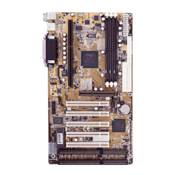
3 HARDWARE INSTALLATION This section outlines how to install and configure your AB61 mainboard. Refer to the following mainboard layout to help you identify various jumpers, connectors, slots, and ports. Then follow these steps designed to guide you through a quick and correct instal- lation of your system. -
Page 13: Step 1 Install The Cpu
Step 1 Install the CPU 1. Mark your CPU Frequency Checking the working frequency of your cpu that should be clearly marked on the CPU cover or write your own combination in the space provided. Pentium II/III Processor Installation <Locate the Retention Mechanism> To install a CPU, first turn off your system and remove its cover. - Page 14 Celeron Processor Installation <Locate the Retention Mechanism> To install a CPU, first turn off your system and remove its cover. Insert two Retention Mechanism (3) on opposite side of Slot 1. Fix (3) by inserting Attach Mounts (4) up through holes (A1...A4) in the bottom of the mainboard, and screw the four captive nuts (3.1).
-
Page 15: Step 2 Set Jumpers
Step 2. Set Jumpers This mainboard is jumperless! The default jumper settings have been set for the common usage standard of this mainboard. Therefore, you do not need to reset the jumpers unless you require special adjustments as in any of the following cases: 1. -
Page 16: Step 4 Install Internal Peripherals In System Case
Step 4 Install Internal Peripherals in System Case Before you install and connect the mainboard into your system case, we recommend that you first assemble all the internal peripheral devices into the computer housing, including but not limited to the hard disk drive (IDE/ HDD), floppy disk drive (FDD), CD-ROM drive, and ATX power supply unit. -
Page 17: Step 5 Mount The Mainboard On The Computer Chassis
Step 5 Mount the Mainboard on the Computer Chassis 1. You may find that there are a lot of different mounting hole positions both on your computer chassis and on the mainboard. To choose a correct mounting hole, the key point is to keep the back-panel of the mainboard in a close fit with your system case, as shown below. -
Page 18: Step 6 Connect Front Panel Switches/Leds/Speaker
Step 6 Connect Front Panel Switches/LEDs/Speaker You can find there are several different cables already existing in the system case and originating from the computer’s front-panel devices (HDD LED, Power LED, Reset Switch, PC Speaker, etc.) These cables serve to connect the front-panel switches and LEDs to the mainboard’s front-panel connectors group, as shown below. - Page 19 4. EPMI (Hardware System Management Interface) 5. Green-LED 6. PC Speaker 7. Hardware Reset Switch 8. Keylock - 17 -...
-
Page 20: Step 7 Connect Ide & Floppy Disk Drives
Step 7 Connect IDE & Floppy Disk Drives 1. IDE cable connector 2. FDD cable connector Step 8 Connect Other Internal Peripherals 1. IR connector Step 9 Connect the Power Supply 1. System power connector - 18 -... -
Page 21: Step 10 Install Add-On Cards In Expansion Slots
Step 10 Install Add-on Cards in Expansion Slots 1. Accelerated Graphics Port (AGP) Card 2. PCI Card 3. ISA Card - 19 -... -
Page 22: Step 11 Connect External Peripherals To Back Panel
Step 11 Connect External Peripherals to Back Panel You are now ready to put the computer case back together and get on to the external peripherals connections to your system’s back-panel. 1. PS/2 Mouse and Keyboard 2. USB Devices 3. Parallel Port 4. -
Page 23: Step 12 First Time System Boot Up
Step 12 First Time System Boot Up To assure the completeness and correctness of your system installation, you may check the above installation steps once again before you boot up your system for the first time. 1. Insert a bootable system floppy disk (DOS 6.2x, Windows 95/98/NT, or others) which contains FDISK and FORMAT utilities into the FDD. -
Page 24: Step 13 Install Drivers & Software Components
Make sure your Windows 9x operating system is already installed before running the drivers installation CD-ROM programs. 1. Insert the AB61 bundled CD-ROM into your CD-ROM drive. The auto-run program will display the drivers main installation window on screen. -
Page 25: Jumper Settings
3.2 Jumper Settings Several hardware settings are made through the use of jumper caps to connect jumper pins on the mainboard. Pin #1 is located on the bottom or on the left when holding the mainboard with the keyboard connector or other back-panel connectors opposite from you, as shown below. -
Page 26: Jumpers & Connectors Guide
Jumpers & Connectors Guide Use the mainboard layout on page 10 to locate CPU socket, memory banks, expansion slots, jumpers and connectors on the mainboard during the installation. The following list will help you identify jumpers, slots, and connectors along with their assigned functions: CPU/Memory/Expansion Slots Slot 1... - Page 27 Front Panel Connectors PWON (S1) : ATX Power On/Off Momentary Type Switch GLED (J48) : Green LED (ON when system in power savings mode) EPMI (J42) : Hardware System Management Interface Momentary Type switch. IDE LED (S3) : IDE Drive Active LED RST (J32) : Hardware Reset Switch SPK (JP24)
-
Page 28: Set Keyboard & Ps/2 Mouse Power-On (Jp38)
Set Keyboard & PS/2 Mouse Power-On (JP38) AB61 mainboard provides an easy power-on by keyboard and PS/2 mouse. Note: When you enable Keyboard Power-On, you also need to configure the proper hot-key combination <Ctrl> + < function key F1 ~ F12 >... -
Page 29: Cpu Host Frequency Setting (Jp39)
CPU host frequency, for setting an incorrect value may damage your CPU. For experienced users, the AB61 mainboard provides an alternative Hard- Configure function to adjust your CPU host frequency manually. -
Page 30: Cpu Clock Ratio Setting (Jp37)
CPU Clock Ratio Setting (JP37 ) AB61 mainboard provides a jumper group JP37 to set CPU speed configure by BIOS or by hardware jumper. By inserting jumper pack on Auto group, the user can Soft-Configure the CPU Host Frequency and CPU Clock Ratio from BIOS. -
Page 31: Cpu Vcore Fine Tune (Jp48)
CPU Vcore Fine tune (JP48) AB61 mainboard supports a 4-pin jumper JP48 to increase CPU Voltage which provide from mainboard. Increase Increase Increase Increase 0.15% CPU 0.5% CPU 1.5% CPU 7.8% CPU Core Voltage Core Voltage Core Voltage Core Voltage Over-Clocking the CPU (J55 &... -
Page 32: Ps/2 Keyboard & Ps/2 Mouse Connectors
PS/2 Keyboard & PS/2 Mouse Connectors Two 6-pin female PS/2 keyboard & Mouse connectors are located at the rear panel of the mainboard. Depending on the com- puter housing you use (desktop or minitower), the PS/2 Mouse connector is situated at the top of the PS/2 Keyboard connector when the mainboard is laid into a desktop, as opposed to a minitower where the PS/2 Mouse connector is lo-... -
Page 33: Atx Power On/Off Switch Connector (Pwon-S1)
ATX Power On/Off Switch Connector (PWON - S1) The Power On/Off Switch is a momen- tary type switch used for turning on or off the system’s ATX power supply. Attach the connector cable from the Power Switch to the 2-pin PWON header on the mainboard. -
Page 34: Hdd Led Connector (Ide Led-S3)
HDD LED Connector (IDE LED - S3) Attach the connector cable from the IDE device LED to the 2-pin HDD LED header. The HDD LED lights up whenever an IDE device is active. Hardware Reset Connector (RST - J32) Attach the 2-pin hardware reset switch cable to the RST header. -
Page 35: Keylock Connector (Keylock-J27)
Enhanced IDE Ports and Floppy Connectors The AB61 mainboard features two 40-pin dual-channel IDE device connec- tors (IDE1/IDE2) providing support for up to four IDE devices, such as CD- ROM and Hard Disk Drives (H.D.D.). This mainboard also includes one 34-pin floppy disk controller (FDC) to accommodate the Floppy Disk Drive (F.D.D.). -
Page 36: Atx Power Supply Connector (J31)
ATX Power Supply Connector (J31) Locate the 20-pin male header ATX power connector (J31) on your mainboard. Plug the power cable from the ATX power supply unit directly into JWR1 ATX power supply connector. Note 1: The ATX power connector is directional and will not go in unless the guides match perfectly making sure that pin#1 is properly positioned. -
Page 37: Ir Connector (Jp4)
IR Connector (JP4) If you have an Infrared device, this mainboard can implement IR transfer function. To enable the IR transfer function, follow these steps: IR Pin Assignments: 1=VCC 2=VCC 3=IRRX 4=Ground 5=IRTX Step 1. Attach the 5-pin infrared device cable to JP4 connector. (Refer to the above diagram for IR pin assignment.) Step 2. -
Page 38: System Memory Configuration
3.3 System Memory Configuration The AB61 mainboard has three 168-pin DIMM sockets that allow you to install from 16MB up to 768MB of system memory with SDRAM (Synchro- nous DRAM). Each DIMM (Dual In-line Memory Module) socket can accommodate 16MB, 32MB, 64MB, 128MB, and 256MB 3.3V single or double side SDRAM modules. -
Page 39: Software Utility
4 SOFTWARE UTILITY 4.1 AB61 Mainboard CD Overview Note: The AB61 mainboard attachment CD contents are subject to change without notice. To start your mainboard CD disc, just insert it into your CD-ROM drive and the CD AutoRun screen should appear. If the AutoRun screen does not appear, double click or run D:\Autorun.exe (assuming that your CD-ROM... -
Page 40: Install Inf Driver
Insert the attachment CD into your CD-ROM drive and the CD AutoRun screen should appear. If the AutoRun screen does not appear, double click on Autorun icon in My Computer to bring up Shuttle Mainboard Software Setup screen. Select using your pointing device (e.g. mouse) on the “Install Mainboard Software”... -
Page 41: To View The User's Manual
Insert the attachment CD into your CD-ROM drive and the CD AutoRun screen should appear. If the AutoRun screen does not appear, double click on Autorun icon in My Computer to bring up Shuttle Mainboard Software Setup screen. Select using your pointing device (e.g. mouse) on the “Manual” bar. -
Page 42: Bios Setup
5 BIOS SETUP AB61 BIOS ROM has a built-in Setup program that allows users to modify the basic system configuration. This information is stored in battery-backed RAM so that it retains the Setup information even if the system power is turned off. -
Page 43: The Main Menu
5.2 The Main Menu Once you enter the AwardBIOS(tm) CMOS Setup Utility, the Main Menu will appear on the screen. The Main Menu allows you to select from several setup functions and two exit choices. Use the arrow keys to select among the items and press <Enter> to accept and enter the sub-menu. - Page 44 Load BIOS Defaults BIOS defaults loads the values required by the System for the maxi- mum performance. However, you can change the parameter through each Setup Menu. Load Setup Defaults Setup defaults loads the values required by the system for the O.K. performance.
-
Page 45: Standard Cmos Setup
Standard CMOS Setup The items in Standard CMOS Setup Menu are divided into 10 catego- ries. Each category includes no, one or more than one setup items. Use the arrow keys to highlight the item and then use the <PgUp> or <PgDn>... - Page 46 If you select Type User, related information is asked to be entered to the following items. Enter the information directly from the keyboard and press <Enter>. Those information should be provided in the documentation from your hard disk vendor or the system manufac- turer.
-
Page 47: Bios Features Setup
BIOS Features Setup Virus Warning When this item is enabled, the Award BIOS will monitor the boot sector and partition table of the hard disk drive for any attempt at modification. If an attempt it made, the BIOS will halt the system and the following error message will appear. - Page 48 Quick Power On Self Test This item speeds up Power On Self Test (POST) after you power on the computer. If it is set to Enabled, BIOS will shorten or skip some check items during POST. Boot Sequence This item determines which drive computer searches first for the disk operating system.
- Page 49 Typematic Rate (Chars/Sec) When the typematic rate is enabled, this selection allows you select the rate at which the keys are accelerated. Typematic Delay (Msec) When the typematic rate is enabled, this selection allows you to select the delay between when the key was first depressed and when the acceleration begins Security Option This item allows you to limit access to the System and Setup, or just to...
-
Page 50: Chipset Features Setup
Chipset Features Setup Auto Configuration The default setting of the optimal timings for items 3 through 7 for 60ns EDO DRAM modules. EDO DRAM Speed Selection This item set the EDO DRAM Read/Write timings that the system uses. When item of "Auto Configuration" is disabled, this item will not show EDO CASx# MA Wait State When enabled, one additional wait state is inserted before the asser- tion of the first memory address line MA and CAS/RAS assertion... - Page 51 SDRAM RAS Precharge Time SDRAM must continually be refreshed or it will lose its data. Nor- mally, DRAM is refreshed entirely as the result of a single request. This option allows you to determine the number of CPU clocks allo- cated for Row Address Strobe to accumulate its charge before the DRAM is refreshed.
- Page 52 8 Bit I/O Recovery Time The recovery time is the length of time, measured in CPU clocks, which the system will delay after the completion of an input/output request. This delay takes place because the CPU is operating so much after than the input/output bus that the CPU must be delayed to allow for the completion of the I/O.
-
Page 53: Power Management Setup
Power Management Setup The Power Management Setup allows you to configure you system to most effectively save energy while operating in a manner consistent with your own style of computer use. ACPI Suspend Type This item determine to support ACPI Suspend Type. Power Management This item determines the options of the power management function. - Page 54 Video Off After This item define when to activate the video off feature for monitor power management. The settings are N/A, Doze, Standby and Sus- pend. MODEM Use IRQ This item determines the IRQ in which the MODEM can use. The choice: 1, 3, 4, 5, 7, 9, 10, 11, N/A.
- Page 55 This item determine the system will resume by activity of LAN. If enabled this feature system will power-on itself from power off when the activity of LAN. Note: AB61 support Wake-ON-LAN function with Intel LAN card only. IRQ 8 Break Suspend You can turn On or Off monitoring of IRQ8 (the Real Time Clock) so it does not awaken the system from Suspend mode.
-
Page 56: Pnp/Pci Configuration
PnP/PCI Configuration This section describes configuring the PCI bus system. PCI, or Per- sonal Computer Interconnect, is a system which allows I/O devices to operate at speeds nearing the speed the CPU itself uses when commu- nicating with its own special components. This section covers some very technical items and it is strongly recommended that only experi- enced users should make any changes to the default settings. - Page 57 DMA 0/1/3/5/6/7 assigned to These items allow you to determine the DMA assigned to the ISA bus and is not available for PCI slot. Choices are Legacy ISA and PCI/ISA PnP. Used MEM base addr This item is used to select a base address for the memory area used by any peripheral that requires high memory.
-
Page 58: Cpu Features Setup
CPU Features Setup Auto Detect DIMM/PCI Clock Enabling this item allosw system auto detect and close clock signal to empty DIMM/PCI slot to reduce EMI. Spread Spectrum This item allows the user to enable Spread Spectrum Modulated to reduce the EMI. CPU Host Clock (CPU/PCI) This item allows the user to adjust CPU Host Bus Clock from BIOS when JP37 is set to Auto. - Page 59 CPU Warning Temperature Since the mainboard support CPU temperature monitoring and over- hear alert. This item allows the user to set the threshold of CPU warning temperature. When CPU temperature over the threshold, system will slow down clock to prevent CPU damage. "This category is not available if optional feature absent."...
-
Page 60: Integrated Peripherals
Integrated Peripherals IDE HDD Block Mode This item is used to set IDE HDD Block Mode. If your IDE Hard Disk supports block mode, then you can enable this function to speed up the HDD access time. If not, please disable this function to avoid HDD access error. - Page 61 USB Keyboard Support This item is used to defined USB Keyboard is Enabled or Disabled. Init Display First This item is used to determine initial device when system power on. The options are PCI and AGP. POWER ON Function This item is used to defined Keyboard & PS/2 mouse power-on func- tion enabled or disabled.
- Page 62 UART Mode Select The main board support IrDA(HPSIR) and Amplitudes Shift Keyed IR(ASKIR) infrared through COM 2 port. This item specifies onboard Infra Red mode to IrDA 1.0, ASKIR, MIR 0.57M, MIR 1.15M, FIR or Standard (Disabled). Note : FIR is not available currently. UART2 Duplex Mode This item specifies onboard infrared transfer mode to full-duplex.
-
Page 63: User Password Setting
User Password Setting You can set either supervisor or user password, or both of then. The differences between are: Supervisor Password and User Password The options on the Password screen menu make it possible to restrict access to the Setup program by enabling you to set passwords for two different access modes: Supervisor mode and User mode. -
Page 64: Save & Exit Setup
Password Disable If you select System at Security Option of BIOS Features Setup Menu, you will be prompted for the password every time the system is rebooted or any time you try to enter Setup. If you select Setup at Security Option of BIOS Features Setup Menu, you will be prompted only when you try to enter Setup.
Need help?
Do you have a question about the AB61 and is the answer not in the manual?
Questions and answers