Table of Contents
Advertisement
Quick Links
Advertisement
Table of Contents

Related Manuals for Shuttle AK32A


Summary of Contents for Shuttle AK32A
- Page 1 AK32A SocketA AMD Athlon/Duron Processor Based DDR/SDR Main Board User's Manual...
- Page 2 The information contained in this manual is provided for general use by the customers. Trademarks Shuttle is a registered trademark of Shuttle Inc. VIA is a registered trademark of VIA Corporation. AMD, Athlon/Duron is a registered trademarks of AMD Corporation.
-
Page 3: Table Of Contents
TABLE OF CONTENTS WHAT'S IN THE MANUAL ..............5 Quick Reference ....................5 About This Manual .................... 5 1 INTRODUCTION .................. 6 1.1 TO DIFFERENT USERS ................6 First-Time DIY System Builder ..............6 Experienced DIY User ................6 System Integrator ..................6 1.2 ITEM CHECKLIST .................. - Page 4 3.2 JUMPER SETTINGS .................. 25 JUMPER & CONNECTOR GUIDE ............26 Jumpers Clear CMOS (JP16) ................29 BIOS Write Protection (JP3) ..............30 Back-Panel Connectors PS/2 Keyboard & PS/2 Mouse Connectors ..........31 USB1/USB2 Port Connectors ..............31 LAN Connector ..................31 COM1/2 Connector ................
- Page 5 Other Connectors ATX Power Supply Connector (JP6) ............38 Cooling FAN Connectors for CPU FANs (FAN1), AGP (FAN2), SYSTEM (FAN3), or North Bridge Fan (FAN4) ............39 SIR/CIR Connector (JP2) ............... 40 Wake-On-LAN Connector (CN1) ............40 Audio Connector CD_In (CN2) (Black) ........... 41 Audio Connector AUX_In (CN3) (White) ..........
- Page 6 PNP/PCI CONFIGURATION............... 70 PC HEALTH STATUS ................. 72 FREQUENCY/VOLTAGE CONTROL ............74 LOAD FAIL-SAFE DEFAULTS..............75 LOAD OPTIMIZED DEFAULTS ..............75 SET SUPERVISOR PASSWORD............... 76 SET USER PASSWORD ................76 SAVE & EXIT SETUP ................. 77 EXIT WITHOUT SAVING ................77 - 4 -...
-
Page 7: What's In The Manual
WHAT'S IN THE MANUAL Quick Reference Hardware Installation >> Step-by-Step ..........Page 11 Jumper Settings >> A Closer Look ............Page 25 Software Utility >> How to Install ............Page 43 BIOS Setup >> How to Configure ............Page 56 About This Manual For First-Time DIY System Builder............ -
Page 8: Introduction
Shuttle AK32A mainboard. Experienced DIY User Congratulate on your purchase of the Shuttle AK32A mainboard. You will find that installing your new Shuttle AK32A mainboard is just easy. Bundled with an array of onboard functions, the highly-integrated AK32A mainboard pro- vides you with a total solution to build the most stable and reliable system. -
Page 9: Item Checklist
1.2 Item Checklist Check all items with your AK32A mainboard to make sure nothing is missing. The complete package should include: One piece of Shuttle AK32A Mainboard FA N 2 I D E 2 I D E 1 P anas on i c... -
Page 10: Features
2 FEATURES AK32A mainboard is carefully designed for the demanding PC user who wants high performance and maximum intelligent features in a compact package. 2.1 Specifications CPU Support Support Socket462 package CPU with 200/266 MHz FSB. AMD Athlon Processor: 600 ~ 1.33+GHz. XP2000+... - Page 11 format or for 5.25-inch FDD with 360K or 1.2MB format. 1*PS/2 mouse connector. 1*PS/2 Keyboard connector. 2*DB9 Serial connectors 16550 UART compatible. 1*Infrared communication port . (Serial port COM2 can also be redirected to an external IrDA Adapter for wireless connection.) 1*DB25 Parallel port supporting Standard Parallel Port (SPP), Enhanced Parallel Port (EPP), and Extended Capabilities Port (ECP) data transmission schemes.
- Page 12 System BIOS Provides licensed Award BIOS V6.0 PG on 2Mb Flash EEPROM and supports Green PC, Desktop Management Interface (DMI). ATX Form Factor System board conforms to the ATX specification. Board dimension: 305mm* 245mm. Advanced Features Dual Function Power Button - Dual Function Power Button - The system can be in one of two states;...
-
Page 13: Hardware Installation
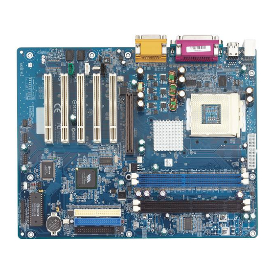
This section outlines how to install and configure your AK32A mainboard. Refer to the following mainboard layout to help you identify various jumpers, connectors, slots, and ports. Then follow these steps to guide you through a quick and correct installation of your system. -
Page 14: Step 1 Install The Cpu
Step 1 Install the CPU: 1. Locate the CPU ZIF (Zero Insertion Force) socket on the upper-right sector of your mainboard (between the back-panel connectors and the DIMM memory slots). 2. Pull the CPU ZIF socket lever slightly sideways away from the socket to unlock the lever, and then bring it to an upwardly vertical position. -
Page 15: Step 2 Set Jumpers
Step 2. Set Jumpers This mainboard is jumperless! The default jumper settings have been set for the common usage standard of this mainboard. Therefore, you do not need to reset the jumpers unless you require special adjustments as in any of the following cases: 1. -
Page 16: Step 4 Install Internal Peripherals In System Case
Step 4 Install Internal Peripherals in System Case Before you install and connect the mainboard into your system case, we recommend that you first assemble all the internal peripheral devices into the computer housing, including but not limited to the hard disk drive (IDE /HDD), floppy disk drive (FDD), CD-ROM drive, and ATX power supply unit. -
Page 17: Step 5 Mount The Mainboard On The Computer Chassis
Step 5 Mount the Mainboard on the Computer Chassis 1. You may find that there are a lot of different mounting hole positions both on your computer chassis and on the mainboard. To choose a correct mounting hole, the key point is to keep the back-panel of the mainboard in a close fit with your system case, as shown below. -
Page 18: Step 6 Connect Front-Panel Switches/Leds/Speaker/Usb
Step 6 Connect Front-Panel Switches/LEDs/Speaker/USB connectors You can find there are several different cables already existing in the system case and originating from the computer's front-panel devices (HDD LED, Power LED, Reset Switch, PC Speaker, or USB devices etc.) These cables serve to connect the front-panel switches, LEDs, USB con- nectors to the mainboard's front-panel connectors group (JP7, JP4 and JP5), as shown below. - Page 19 SPEAK P LED 3. Green_LED (GLED) 1 RST HLED GLED EPMI PWR PT SPEAK P LED 4. HDD_LED (HLED) 1 RST HLED GLED EPMI PWR PT SPEAK P LED 5. Power-LED (PLED) 1 RST HLED GLED EPMI PWR PT 6. Hardware Reset Switch (RST) SPEAK P LED 1 RST...
-
Page 20: Step 7 Connect Ide & Floppy Disk Drives
8. Extended four USB Connector Header USB3 (USB5) JP4 (JP5 ) USB4 (USB6) Step 7 Connect IDE & Floppy Disk Drives 1. IDE cable connector IDE2 IDE1 2. FDD cable connector - 18 -... -
Page 21: Step 8 Connect Other Internal Peripherals
Step 8 Connect Other Internal Peripherals 1. CD_IN, TAD_IN, and AUX_IN connectors CD-IN TAD/IO 2. IR connector Step 9 Connect Power Supply 1. System power connector - 19 -... -
Page 22: Step 10 Install Add-On Cards In Expansion Slots
Step 10 Install Add-on Cards in Expansion Slots 1. Accelerated Graphics Port (AGP) Card 2. PCI Card - 20 -... -
Page 23: Step 11 Connect External Peripherals To Back-Panel
Step 11 Connect External Peripherals to Back-Panel You are now ready to put the computer case back together and get on to the external peripherals connections to your system's back-panel. USB1 CON1 AUDIO1 1. PS/2 Mouse and Keyboard PS/2 Mouse PS/2 keyboard USB2 2. - Page 24 4. COM1/2 Port COM1 COM2 5. Audio Line_out / Line_in / Mic_in Purts Line-In Mic_in Line-Out 6. MIDI/Game Port MIDI/GAME Port - 22 -...
-
Page 25: Step 12 First Time System Boot Up
Step 12 First Time System Boot Up To assure the completeness and correctness of your system installation, you may check the above installation steps once again before you boot up your system for the first time. 1. Insert a bootable system floppy disk (DOS 6.2x, Windows 95/98/NT, or others) which contains FDISK and FORMAT utilities into the FDD. -
Page 26: Step 13 Install Driver & Software Components
Make sure your Windows 9x operating system is already installed before running the drivers installation CD-ROM programs. 1. Insert the AK32A bundled CD-ROM into your CD-ROM drive. The auto-run program will display the drivers main installation window on screen. -
Page 27: Jumper Settings
3.2 Jumper Settings Several hardware settings are made through the use of jumper caps to con- nect jumper pins to the mainboard. Pin #1 could be located at any corner of each jumper; you just find a location marked with a while right angle, which stands for pin1#. -
Page 28: Jumper & Connector Guide
Jumper & Connector Guide Use the mainboard layout on page 12 to locate CPU socket, memory slots, expansion slots, jumpers and connectors on the mainboard during installation. The following list will help you identify jumpers, slots, and connectors along with their assigned functions: B3~B4 B5~B8 C1~C7... - Page 29 Jumpers JP16 : Clear CMOS : BIOS Write Protection Back-Panel Connectors : PS/2 Keyboard : PS/2 Mouse : 2 USB (Universal Serial Bus) COM1 : Serial Port 1 (DB9 male) COM2 : Serial Port 2 (DB9 male) PRINTER : Parallel Port (DB25 female) LINE-OUT : Line-Out Port LINE-IN...
- Page 30 : IR Connector : Wake-On-LAN Connector : CD-in : AUX-in : TAD-in - 28 -...
-
Page 31: Jumpers Clear Cmos (Jp16)
Jumpers Clear CMOS (JP16) JP16 is used to clear CMOS data. Clearing CMOS will result in the permanent erasing of previous system configuration settings and the restoration of original (factory-default) system settings. Pin 1-2 (Default) Pin 2-3 (Clear CMOS) JP16 Step 1. -
Page 32: Bios Write Protection (Jp3)
Step 2. Make sure of place jumper cap on JP3 pin 2-3. Step 2. Step 2. Step 3. Step 3. Step 3. Step 3. Step 3. Insert a bootable system floppy disk with AK32A BIOS and flashutility and then turn on your system to execute flash utility. - 30 -... -
Page 33: Back-Panel Connectors Ps/2 Keyboard & Ps/2 Mouse Connectors
Back-Panel Connectors PS/2 Keyboard & PS/2 Mouse Connectors Two 6-pin female PS/2 keyboard & Mouse connectors are located at the rear panel PS/2 Mouse of mainboard. Depending on the com- puter housing you use (desktop or tower), the PS/2 Mouse connector is situated at the top of the PS/2 Keyboard connector when the mainboard is laid into a desk- PS/2 keyboard... -
Page 34: Parallel Port Connector
Line-Out Line-Out is a stereo output port through which the combined signal of all internal and external audio sources on the board is output. It can be connected to 1/8-inch TRS stereo headphones or to amplified Line-Out speakers. Line-In Line-In is a stereo line-level input port that accepts a 1/8-inch TRS stereo plug. -
Page 35: Front-Panel Connectors Atx Power On/Off Switch Connector (Pwr Pt)
Front-Panel Connectors ATX Power On/Off Switch Connector (PWR PT) The Power On/Off Switch is a momentary- type switch used for turning on or off the system's ATX power supply. Attach the connector cable from the Power Switch to the 2-pin PWR PT header on the mainboard. P LED SPEAK 1 RST... -
Page 36: Green Led Connector (Gled)
Green LED Connector (GLED) The Green LED (GLED) indicates that the system is currently in one of the power saving mode (Doze/Standby/Suspend). When the system resumes to normal operation mode, the Green LED will go off. Attach a 2-pin Green LED cable to GLED header. -
Page 37: Hardware Reset Connector (Rst)
Hardware Reset Connector (RST) Attach the 2-pin hardware reset switch cable to the RST header. Pressing the reset switch causes the system to restart. P LED SPEAK 1 RST HLED GLED EPMI PWR PT Speaker Connector (SPEAK) Attach the PC speaker cable from the case to the 4-pin speaker connector (SPEAK). -
Page 38: Extended Four Usb Connector Header (Jp1/Jp5)
Extended four USB Connector Header (JP4/JP5) The headers are used to connect the cable attached to USB connectors which are mounted on front-panel or back-panel. But the USB cable is optional at the time of purchase. USB3 USB2 USB3 (USB5 JP4 (JP5 ) 10 8 USB4 (USB6... -
Page 39: Internal Peripherals Connectors Enhanced Ide Ports And Floppy Connectors
Internal Peripherals Connectors Enhanced IDE Ports and Floppy Connector The AK32A mainboard features two 40-pin dual-channel IDE device connec- tors (IDE1/IDE2) providing support to up to four IDE devices, such as CD- ROM and Hard Disk Drives (H.D.D.). This mainboard also includes one 34- pin floppy disk controller (FDC) to accommodate the Floppy Disk Drive (F.D.D.). -
Page 40: Other Connectors Atx Power Supply Connector (Jp6)
Other Connectors ATX Power Supply Connector (JP6) Locate the 20-pin male header ATX power connector (JP6) on your mainboard. Plug the power cable from the ATX power supply unit directly into JP6 ATX power supply connector. Note 1: Note 1: Note 1: Note 1: Note 1: The ATX power connector is directional and will not go in unless... -
Page 41: Cooling Fan Connectors For Cpu Fans (Fan1), Agp (Fan2), System (Fan3), Or North Bridge Fan (Fan4)
Cooling Fan Connectors for CPU (FAN1), AGP (FAN2), SYSTEM (FAN3), and North Bridge ( FAN4) Fan The mainboard provides four onboard 12V cooling fan power connectors to support CPU FAN (FAN1), AGP (FAN2), SYSTEM (FAN3), and North Bridge (FAN4) cooling fans. FAN1 CPU_FAN NB_FAN... -
Page 42: Sir/Cir Connector (Jp2)
SIR/CIR Connector (JP2) If you have an Infrared device, this mainboard can implement SIR (Standard IR) and CIR (Cirsumer IR) transfer function. To enable the IR transfer func- tion, follow these steps: 1 2 3 4 Pins Assignment: 1=+5V 2=CIRRX 3=IRRX 4=GND 5=IRTX Note: Note:... -
Page 43: Audio Connector Cd_In (Cn2) (Black)
4=AUX_R Audio Connector TAD _In (CN4) (Green) Port CN4 can be used to connect a modem audio line to AK32A mainboard. Typically, you would use this connector when running the voice mail software on your system for audio input and output. -
Page 44: System Memory Configuration
3.3 System Memory Configuration The AK32A mainboard has two 184-pin and two 168-pin DIMM slots that allow you to install from 16MB up to 2GB of system memory. Each 184-pin DIMM (Dual In-line Memory Module) slot can accommodate 64MB, 128MB, 256MB, 512MB, and 1GB of PC1600/PC2100 compliant 2.5V single or double side 64-bit wide data path DDR SDRAM modules. -
Page 45: Software Utility
4 SOFTWARE UTILITY 4.1 Mainboard CD Overview Note: The CD contents attached in the AK32A mainboard are subject to change without notice. To start your mainboard CD disc, insert it into your CD-ROM drive, and the CD AutoRun screen should appear. If the AutoRun screen does not appear, double click or run D:\Autorun.exe (assuming that your CD-ROM... -
Page 46: Install Via 4 In 1 Driver
Insert the attached CD into your CD-ROM drive, and the CD AutoRun screen should appear. If the AutoRun screen does not appear, double click on Autorun icon in My Computer to bring up Shuttle Mainboard Software Setup screen. Select the item using your pointing device (e.g. mouse) on the “Install Mainboard Software"... -
Page 47: Install Audio Device Software
Insert the attached CD into your CD-ROM drive, and the CD AutoRun screen should appear. If the AutoRun screen does not appear, double click on Autorun icon in My Computer to bring up Shuttle Mainboard Software Setup screen. Select the item using your pointing device (e.g. mouse) on the “Install Audio Device Software"... -
Page 48: View The User's Manual
Select the item using your pointing device (e.g. mouse) on the “Manual” bar. Then Online Information windows will appear on the screen. Click on the “Install Acrobat Reader" bar if you need to install acrobat reader. Then click on " AK32A Manual" bar to view AK32A user's manual. - 46 -... -
Page 49: Bios Setup
5 BIOS SETUP AK32A BIOS ROM has a built-in Setup program that allows users to modify the basic system configuration. This information is stored in battery-backed RAM so that it retains the Setup information even if the system power is turned off. -
Page 50: The Main Menu
5.2 The Main Menu Once you enter the AwardBIOS(tm) CMOS Setup Utility, the Main Menu will appear on the screen. The Main Menu allows you to select from several setup functions and two exit choices. Use the arrow keys to select among the items and press <Enter> to accept and enter the sub-menu. - Page 51 Power Management Setup Use this menu to specify your settings for power management. PnP / PCI Configuration This entry appears if your system supports PnP / PCI. PC Health Status This entry shows the current system temperature, Voltage, and FAN speed.
-
Page 52: Standard Cmos Features
Standard CMOS Features The items in Standard CMOS Setup Menu are divided into 10 catego- ries. Each category includes no, one or more than one setup items. Use the arrow keys to highlight the item and then use the <PgUp> or <PgDn>... - Page 53 IDE Secondary Master IDE Secondary Master IDE Secondary Master IDE Secondary Master IDE Secondary Master Options are in its sub-menu. Press <Enter> to enter the sub-menu of detailed options. IDE Secondary Slave IDE Secondary Slave IDE Secondary Slave IDE Secondary Slave IDE Secondary Slave Options are in its sub menu.
- Page 54 ****************************************************** ****************************************************** ****************************************************** ****************************************************** ****************************************************** IDE Adapters The IDE adapters control the hard disk drive. Use a separate sub-menu to configure each hard disk drive. IDE HDD Auto-Detection IDE HDD Auto-Detection IDE HDD Auto-Detection IDE HDD Auto-Detection IDE HDD Auto-Detection Press <Enter>...
- Page 55 Precomp Precomp Precomp Precomp Precomp Warning: Setting a value of 65535 means no hard disk. Min = 0, Max = 65535 Landing zone Landing zone Landing zone Landing zone Landing zone Set the Landing zone size. Min = 0, Max = 65535 Sector Sector Sector...
-
Page 56: Advanced Bios Features
Advanced BIOS Features This section allows you to configure your system for basic operation. You have the opportunity to select the system's default speed, boot-up sequence, keyboard operation, shadowing, and security. Virus Warning Virus Warning Virus Warning Virus Warning Virus Warning Allows you to choose the VIRUS Warning feature for IDE Hard Disk boot sector protection. - Page 57 CPU L2 Cache ECC Checking CPU L2 Cache ECC Checking CPU L2 Cache ECC Checking CPU L2 Cache ECC Checking CPU L2 Cache ECC Checking When you select Enabled, memory checking is enabled when the CPU internal L2 cache contains ECC SRAMs. The choice: Enabled or Disabled.
- Page 58 Typematic Rate Setting Typematic Rate Setting Typematic Rate Setting Typematic Rate Setting Typematic Rate Setting Keystrokes repeat at a rate determined by the keyboard controller. When this controller enabled, the typematic rate and typematic delay can be selected. The choice: Enabled or Disabled. Typematic Rate (Chars/Sec) Typematic Rate (Chars/Sec) Typematic Rate (Chars/Sec)
- Page 59 Video BIOS Shadow Video BIOS Shadow Video BIOS Shadow Video BIOS Shadow Video BIOS Shadow Determines whether video BIOS will be copied to RAM. However, it is optional depending on chipset design. Video Shadow will increase the video speed. The choice: Enabled or Disabled. Small Logo(EPA) Show Small Logo(EPA) Show Small Logo(EPA) Show...
-
Page 60: Advanced Chipset Features
Advanced Chipset Features This section allows you to configure the system based on the specific features of the installed chipset. This chipset manages bus speeds and access to system memory resources, such as DRAM and the external cache. It also coordinates communications between the conventional ISA bus and the PCI bus. - Page 61 When CPU speed set to 133MHz, DRAM speed only set to 133MHz (by Host Clock). DRAM Timing DRAM Timing DRAM Timing DRAM Timing DRAM Timing This item allows you to select the value in this field, depending on whether the board using which kind of DDR DRAM. The Choice: Manual or By SPD.
- Page 62 AGP Driving Control AGP Driving Control AGP Driving Control AGP Driving Control AGP Driving Control This item enables the system to automatically select its output buffer drive strength or make it manually selectable by an end user. The Choice: Auto or Manual. AGP Driving Value AGP Driving Value AGP Driving Value...
- Page 63 PCI1 Post Write PCI1 Post Write PCI1 Post Write PCI1 Post Write PCI1 Post Write This Item enable/disable AGP post write function, which means when cpu accessing the AGP data, the chipset can queue the instruction when the AGP bus is busy,then write the data when AGP bus is avail- able .
-
Page 64: Integrated Peripherals
Integrated Peripherals VIA OnChip IDE Device VIA OnChip IDE Device VIA OnChip IDE Device VIA OnChip IDE Device VIA OnChip IDE Device Options are in its sub-menu. Press <Enter> to enter the sub-menu of detailed options. OnChip IDE Channel0 OnChip IDE Channel0 OnChip IDE Channel0 OnChip IDE Channel0 OnChip IDE Channel0... - Page 65 Primary/Secondary Master/Slave PIO Primary/Secondary Master/Slave PIO Primary/Secondary Master/Slave PIO Primary/Secondary Master/Slave PIO Primary/Secondary Master/Slave PIO The four IDE PIO (Programmed Input/Output) fields let you set a PIO mode (0-4) for each of the four IDE devices that the onboard IDE inter- face supports.
- Page 66 UART Mode Select UART Mode Select UART Mode Select UART Mode Select UART Mode Select This item allows you to select which mode for the Onboard Serial Port 2. The choice: IrDA, ASKIR, or Normal. RxD, TxD Active RxD, TxD Active RxD, TxD Active RxD, TxD Active RxD, TxD Active...
- Page 67 ECP Mode Use DMA ECP Mode Use DMA ECP Mode Use DMA ECP Mode Use DMA ECP Mode Use DMA Select a DMA channel for the parallel port for use during ECP mode. The choice: 1 or 3. Game Port Address Game Port Address Game Port Address Game Port Address...
-
Page 68: Power Management Setup
Power Management Setup The Power Management Setup allows you to configure your system to most effectively saving energy while operating in a manner con- sistent with your own style of computer use. ACPI Function ACPI Function ACPI Function ACPI Function ACPI Function This item allows you to enable/disable the Advanced Configuration and Power Management (ACPI). - Page 69 HDD Power Down HDD Power Down HDD Power Down HDD Power Down HDD Power Down When this item enabled and after the set up time of system inactiv- ity, the hard disk drive will be powered down while all other de- vices remain active.
- Page 70 State After Power Failure State After Power Failure State After Power Failure State After Power Failure State After Power Failure This allows you to set whether you want your system to reboot after power has been interrupted. The choice: Auto or Off. IRQ/Event Activity Detect IRQ/Event Activity Detect IRQ/Event Activity Detect...
- Page 71 Data (of Month) Data (of Month) Data (of Month) Data (of Month) Data (of Month) This item selects the alarm date. Key in a DEC number:Min=0, Max=31. Resume Time (hh:mm:ss) Resume Time (hh:mm:ss) Resume Time (hh:mm:ss) Resume Time (hh:mm:ss) Resume Time (hh:mm:ss) This item selects the alarm Time.
- Page 72 PnP/PCI Configuration This section describes the configuration of PCI bus system. PCI or Personal Computer Interconnection is a system which allows I/O devices to operate at the speed CPU itself keeps when CPU communicating with its own special components. This section covers some very technical items, and it is strongly recommended that only experienced users should make any changes to the default settings.
- Page 73 If you set this field to "manual" , choose specific resources by going into each of the sub-menu that follows this field (a sub-menu is pro- ceeded by a ">"). The choice: Auto(ESCD) or Manual. IRQ Resources IRQ Resources IRQ Resources IRQ Resources IRQ Resources When resources are controlled manually, assign each system interrupt...
- Page 74 PC Health Status CPU Warning Temperature CPU Warning Temperature CPU Warning Temperature CPU Warning Temperature CPU Warning Temperature Since the mainboard support System and CPU temperature monitor- ing and overheat alert. This item allows the user to set the threshold of CPU warning temperature.
- Page 75 +3.3VIN, +5V, +12V, -12V, -5V +3.3VIN, +5V, +12V, -12V, -5V +3.3VIN, +5V, +12V, -12V, -5V +3.3VIN, +5V, +12V, -12V, -5V +3.3VIN, +5V, +12V, -12V, -5V The mainboard support CPU and mainboard voltages monitoring. The onboard hardware monitor is able to detect the voltages output of the voltage regulators and power supply.
- Page 76 Frequency/Voltage Control CPU Voltage CPU Voltage CPU Voltage CPU Voltage CPU Voltage This item show the voltage set after fine tuning. CPU Voltage default CPU Voltage default CPU Voltage default CPU Voltage default CPU Voltage default This item show CPU voltage is set by manufacturer prior to delivery. CPU Vcore Select CPU Vcore Select CPU Vcore Select...
- Page 77 Load Fail-Safe Defaults When you press <Enter> on this item, you will get a confirmation dialog box with a message similar to: Load Fail-Safe Defaults (Y/N) ? N Pressing 'Y' loads the BIOS default values for the most stable, minimal performance system operations. Load Optimized Defaults When you press <Enter>...
- Page 78 Supervisor/User Password Setting You can set either supervisor or user password, or both of them. The differences between them are: Supervisor Password and User Password Supervisor Password and User Password Supervisor Password and User Password Supervisor Password and User Password Supervisor Password and User Password The options on the Password screen menu make it possible to restrict access to the Setup program by enabling you to set passwords for two...
- Page 79 Password Disable Password Disable Password Disable Password Disable Password Disable If you select System at Security Option of BIOS Features Setup Menu, you will be prompted in entering the password whenever the system is rebooted or you try to enter Setup. If you select Setup at Security Option of BIOS Features Setup Menu, you will be prompted only when you try to enter Setup.
Need help?
Do you have a question about the AK32A and is the answer not in the manual?
Questions and answers