Table of Contents
Advertisement
Quick Links
Advertisement
Table of Contents

Related Manuals for Shuttle Spacewalker AB40


Summary of Contents for Shuttle Spacewalker AB40
- Page 1 AB40/AB40R Pentium 4 Processor Based DDR MAIN BOARD User's Manual...
- Page 2 The information contained in this manual is provided for general use by the customers. Trademarks Spacewalker is a registered trademark of Shuttle Inc. Intel, Pentium is a registered trademarks of Intel Corporation. PS/2 is a registered trademark of IBM Corporation.
-
Page 3: Table Of Contents
TABLE OF CONTENTS WHAT’S IN THE MANUAL ..............5 Quick Reference ....................5 About This Manual .................... 5 1 INTRODUCTION ................. 6 1.1 TO DIFFERENT USERS ................6 FIRST-TIME DIY SYSTEM BUILDER ............6 EXPERIENCED DIY USER ................. 6 SYSTEM INTEGRATOR ................6 1.2 ITEM CHECKLIST: .................. - Page 4 STEP 13 Install Drivers & Software Components ........25 3.2 JUMPER SETTINGS .................. 26 JUMPERS & CONNECTORS GUIDE ............ 27 Jumpers Clear CMOS Setting (JP1) ..............30 On board RAID Enable/Disable Setting (JP18) (AB40R only) ....31 Back-Panel Connectors PS/2 Keyboard & PS/2 Mouse Connectors ..........32 USB1/USB2 Port Connectors ..............32 COM1/2 Port Connectors ...............
- Page 5 Internal Peripherals Connectors Enhanced IDE, IDE RAID, and Floppy Connector ........38 Other Connectors ATX Power Supply Connector (CN7, JP12, and JP13) ......39 Cooling Fan Connectors for CPU (FAN1), AGP (FAN2), chipset (FAN3), System (FAN4) ..................40 IR Header (JP16) ................... 40 Audio CD-IN Connector (CN5) (Black) ............
- Page 6 5 BIOS SETUP ..................51 5.1 ENTER BIOS ....................51 5.2 THE MAIN MENU ..................52 STANDARD CMOS FEATURES ..............54 ADVANCED BIOS FEATURES ..............58 ADVANCED CHIPSET FEATURES ............62 INTEGRATED PERIPHERALS ..............65 POWER MANAGEMENT SETUP .............. 70 PNP/PCI CONFIGURATION ............... 74 PC HEALTH STATUS .................
-
Page 7: What's In The Manual
WHAT’S IN THE MANUAL Quick Reference Hardware Installation >> Step-by-Step ..........Page 11 Jumper Settings >> A Closer Look ............Page 26 Drivers/Software Utilities >> How to Install ......... Page 44 BIOS Setup >> How to Configure ............Page 51 About This Manual For First-Time DIY System Builder ............ -
Page 8: Introduction
1 INTRODUCTION 1.1 To Different Users First-Time DIY System Builder Experienced DIY User System Integrator - 6 -... -
Page 9: Item Checklist
1.2 Item Checklist: C M I 8 7 3 8 / P C I - 6 c h - L X H R T F 3 D A u d i o M C X 5 8 . 0 2 - 0 1 1 0 U G G D A F A N 3 C N 7... -
Page 10: Features
2 FEATURES 2.1 Specifications CPU Support Chipset CPU FSB Configuration by 1MHz step On Board Multi-Channel Hardware Audio Controller On Board IDE RAID Controller (AB40R only) Versatile Memory Support PCI Expansion Slots AGP Expansion Slots ... - Page 11 I/O Interface Ø Ø Ø Ø Ø Ø Ø Ø Ø Ø PCI Bus Master IDE Controller Onboard ATX Power Supply Connector Advanced Configuration and Power Interface - 9 -...
- Page 12 System BIOS ATX Form Factor Advanced Features Ø Ø Ø Ø Ø Ø Intelligent Features Ø Ø Ø - 10 -...
-
Page 13: Hardware Installation
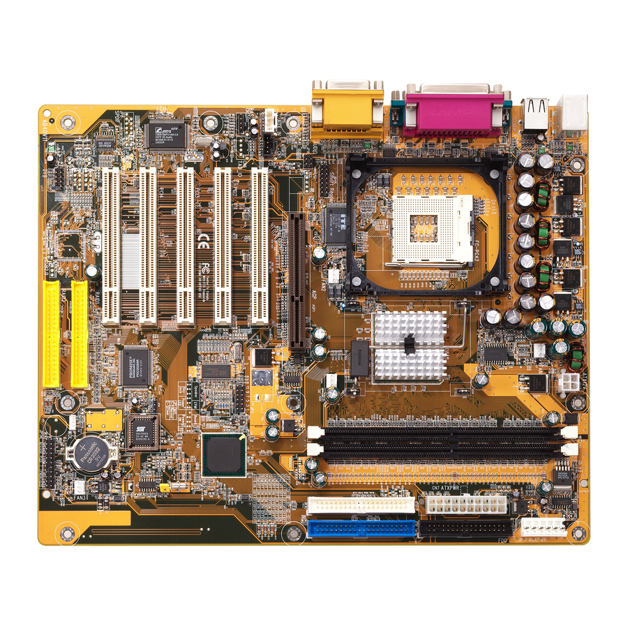
3 HARDWARE INSTALLATION 3.1 Step-by-Step Installation Accessories Of AB40/AB40R ATX 12V Power Connector INTEL 82845 Chipset Two DIMM Slots SOCKET 478 FAN2 FAN1 K B_ MS PS/2 Keyboard and DI MM1 DI MM2 PS/2 Mouse Connectors ATX 1 2 V J P1 3 U SB FAN1... -
Page 14: Step 1 Install The Cpu
Step 1 CPU Installation: CPU socket lever up to 90 degree CPU pin 1 and cut edge - 12 -... - Page 15 - 13 -...
-
Page 16: Step 2 Set Jumpers
Step 2. Set Jumpers Step 3 Install DDR SDRAM System Memory - 14 -... -
Page 17: Step 4 Install Peripherals In System Case
Step 4 Install Internal Peripherals in System Case - 15 -... -
Page 18: Step 5 Mount The Mainboard On The Computer Chassis
Step 5 Mount the Mainboard on the Computer Chassis - 16 -... -
Page 19: Step 6 Connect Front Panel Switches/Leds/Speaker/Usb
Step 6 Connect Front Panel Switches/LEDs/Speaker/USB SPEAKER EPMI R ST H LED JP1 4 KEYLOC K PLED PW ON G LED PLED S PE A KER E PM I R ST H LE D JP 1 4 K EY LO C K P LE D P W O N G LE D /P L E D... - Page 20 S PE A KER E PM I R ST H LE D JP 1 4 K EY LO C K P LE D P W O N G LE D /P L E D E PM I S PE A KE R R S T H LE D JP 1 4...
-
Page 21: Step 7 Connect Ide, Ide Raid, And Floppy Disk Drives
USB port 4 USB port 3 Step 7 Connect IDE, IDE RAID, and Floppy Disk Drives IDE2 IDE1 R AID 1 R AID 2 - 19 -... -
Page 22: Step 8 Connect Other Internal Peripherals
F LP 1 Step 8 Connect Other Internal Peripherals AU X_IN C N 5 C N 4 C D -IN B A S S JP17 JP16 - 20 -... -
Page 23: Step 9 Connect The Power Supply
Step 9 ATX12V J P 13 Connect the Power Supply Step 10 Install Add-on Cards in Expansion Slots - 21 -... -
Page 24: Step 11 Connect External Peripherals To Back Panel
Step 11 Connect External Peripherals to Back-Panel KB _MS US B CO M1 C O M 2 P R T A U D I O - 22 -... - Page 25 foxcon n - 23 -...
-
Page 26: Step 12 First Time System Boot Up
Step 12 First Time System Boot Up - 24 -... -
Page 27: Step 13 Install Drivers & Software Components
Step 13 Install Drivers & Software Components - 25 -... -
Page 28: Jumper Settings
3.2 Jumper Settings Caution! - 26 -... -
Page 29: Jumpers & Connectors Guide
Jumpers & Connectors Guide B3~B4 B5~B8 C1~C8 CPU/Memory/Expansion Slots - 27 -... -
Page 30: Jumpers
Jumpers Back Panel Connectors Front Panel Connectors Internal Peripherals Connectors - 28 -... - Page 31 Other Connectors - 29 -...
-
Page 32: Clear Cmos Setting (Jp1)
Jumpers Clear CMOS Setting (JP1) - 30 -... -
Page 33: On Board Raid Enable/Disable Setting (Jp18) (Ab40R Only)
On board RAID Enable/Disable Setting (JP18) (AB40R only) JP18 - 31 -... -
Page 34: Back-Panel Connectors Ps/2 Keyboard & Ps/2 Mouse Connectors
Back-Panel Connectors PS/2 Keyboard & PS/2 Mouse Connectors USB1/USB2 Port Connectors COM1/2 Port Connectors Parallel Port Connector foxc on n - 32 -... -
Page 35: Line-Out (Front-Out) Port Connector
Line-Out (Front-Out) Port Connector Line-In (Rear-Out) Port Connector Mic-In Port Connector MIDI/GAME Port Connector - 33 -... -
Page 36: Front-Panel Connectors Atx Power On/Off Switch Connector (Pwon)
Front-Panel Connectors ATX Power On/Off Switch Connector (PWON) SPEAKER EPMI R ST H LED JP1 4 KEYLOC K PLED PW ON G LED/PL ED EPMI Connector (EPMI) EPMI SPEAKER R ST H LED JP1 4 KEYLOC K PLED PW ON G LED/PL ED - 34 -... -
Page 37: Green Led/Power Led Connector (Gled/Pled)
Green LED/Power LED Connector (GLED/PLED) GLED PLE D EPMI SPEAKER R ST H LED JP1 4 KEYLOC K PLED PW ON G LED/PL ED HDD LED Connector (HLED) SPEAKER EPMI R ST H LED JP1 4 KEYLOC K PLED PW ON G LED/PL ED - 35 -... -
Page 38: Power Led Connector (Pled)
Power LED Connector (PLED) EPMI SPEAKER R ST H LED JP14 KEYLO CK PLED PW ON G LED/PL ED Hardware Reset Connector (RST) EPMI SPEAKER R ST H LED JP1 4 KEYLOC K PLED PW ON G LED/PL ED Keylock Connector (KEYLOCK) SPEAKER EPMI R ST... -
Page 39: Speaker Connector (Speaker)
Speaker Connector (SPEAKER) EPMI SPEAKER R ST H LED JP1 4 KEYLOC K PLED PW ON G LED/PL ED Extended USB Header (JP4) USB port 4 USB port 3 - 37 -... -
Page 40: Internal Peripherals Connectors
Internal Peripherals Connectors Enhanced IDE, IDE RAID (AB40R only), and Floppy Connectors FLP1 IDE2 IDE1 RAI D 1 RAI D 2 - 38 -... -
Page 41: Other Connectors
Other Connectors ATX Power Supply Connector (CN7, JP12, and JP13) ATX12V J P 13 JP12 JP13 - 39 -... -
Page 42: System (Fan4)
CPU, AGP, Chipset and System Fan connectors - FAN1/2/3/4 FAN 1 FAN 2 FAN 4 IR Header (JP16) 2 4 6 JP16 1 3 5 - 40 -... -
Page 43: Audio Cd-In Connector (Cn5) (Black)
Audio CD_IN Connector (CN5) (Black) 4 3 2 1 C N 5 C D -IN Audio AUXILIARY_IN Connectorr (CN4) (White) 4 3 2 1 AU X_IN C N 4 Audio Bass/Center_Out Header (JP17) 4 3 2 1 B A S S JP17 - 41 -... -
Page 44: Wake-On Lan Connector (Jp3)
Wake-On-LAN Connector (JP3) 3 2 1 W O L Smart Card header (JP15) 1 3 11 9 7 5 3 1 JP15 Sm art R eader 1 4 1 2 1 0 8 6 4 2 - 42 -... -
Page 45: System Memory Configuration
3.3 System Memory Configuration 1. Install Memory: Maximum installed memory is 2GB. 2. Upgrade Memory: - 43 -... -
Page 46: Software Utility
4 SOFTWARE UTILITY 4.1 Mainboard CD Overview - 44 -... -
Page 47: Install Mainboard Software
4.2 Install Mainboard Software - 45 -... -
Page 48: A Install Chipset System Driver
4.2.A Install Chipset System Driver Note: When the Windows 95/98 first reboot after Intel Chipset System drivers installed, some new hardware devices will be found and added. For those new hardware devices, related software driver will be searched for installing. The user may find the software drivers retain on directory C:\windows\system if some of software drivers could not be found during searching. -
Page 49: B Install Ide Driver
4.2.B Install IDE Driver - 47 -... -
Page 50: C Install Audio Driver
4.2.C Install Audio Driver - 48 -... -
Page 51: D Install Ide Raid Driver (Ab40R Only)
4.2.D Install IDE RAID Driver (AB40R only) - 49 -... -
Page 52: View The User's Manual
4.3 View the User's Manual - 50 -... -
Page 53: Bios Setup
5 BIOS SETUP 5.1 Enter the BIOS - 51 -... -
Page 54: The Main Menu
5.2 The Main Menu Setup Items Standard CMOS Features Advanced BIOS Features Advanced Chipset Features Integrated Peripherals Power Management Setup - 52 -... - Page 55 PnP / PCI Configurations PC Health Status Frequency/Voltage Control Load Fail-Safe Defaults Load Optimized Defaults Supervisor / User Password Save & Exit Setup Exit Without Saving - 53 -...
-
Page 56: Standard Cmos Features
Standard CMOS Features - 54 -... - Page 57 Ø Ø Ø Ø Ø Ø - 55 -...
- Page 58 IDE Adapters Ø Ø Ø Ø The following options are selectable only if the 'IDE Primary Master' item is set to 'Manual' Ø Ø - 56 -...
- Page 59 Ø Ø Ø - 57 -...
-
Page 60: Advanced Bios Features
Advanced BIOS Features Ø Ø - 58 -... - Page 61 Ø Ø Ø Ø Ø Ø Ø Ø - 59 -...
- Page 62 Ø Ø Ø Ø Ø Ø - 60 -...
- Page 63 Ø Ø Ø Ø - 61 -...
-
Page 64: Advanced Chipset Features
Advanced Chipset Features Ø Ø Ø - 62 -... - Page 65 Ø Ø Ø Ø Ø Ø Ø - 63 -...
- Page 66 Ø Ø Ø Ø Ø - 64 -...
-
Page 67: Integrated Peripherals
Integrated Peripherals Ø Ø - 65 -... - Page 68 Ø Ø Ø Ø Ø Ø - 66 -...
- Page 69 Ø Ø Ø Ø Ø Note USB Keyboard, USB Mouse and Serial Mouse are not supported to this function. Ø Ø - 67 -...
- Page 70 Ø Ø Ø Ø Ø Ø Ø Ø Ø - 68 -...
- Page 71 Ø Ø Ø - 69 -...
-
Page 72: Power Management Setup
Power Management Setup Ø Ø - 70 -... - Page 73 Ø Ø Ø Ø Ø Ø - 71 -...
- Page 74 Ø Ø Ø Ø Ø Ø Ø Ø Ø - 72 -...
- Page 75 Ø - 73 -...
-
Page 76: Pnp/Pci Configuration
PnP/PCI Configurations Ø Ø - 74 -... - Page 77 Ø Ø Ø - 75 -...
-
Page 78: Pc Health Status
PC Health Status Shutdown Temperature Ø - 76 -... - Page 79 - 77 -...
-
Page 80: Frequency/Voltage Control
Frequency/Voltage Control Ø Ø Ø Ø Ø - 78 -... -
Page 81: Load Fail-Safe Defaults
Load Fail-Safe Defaults Load Optimized Defaults - 79 -... -
Page 82: Set Supervisor Password
- 80 -... - Page 83 Warning : - 81 -...
-
Page 84: Save & Exit Setup
Save & Exit Setup Exit Without Saving - 82 -...
Need help?
Do you have a question about the Spacewalker AB40 and is the answer not in the manual?
Questions and answers