Table of Contents
Advertisement
Quick Links
Advertisement
Table of Contents

Subscribe to Our Youtube Channel
Related Manuals for Shuttle AB60/R


Summary of Contents for Shuttle AB60/R
- Page 1 AB60/R Pentium 4/Celeron Based MAIN BOARD 478-pin Processor User's Manual...
- Page 2 The information contained in this manual is provided for general use by the customers. Trademarks Shuttle is a registered trademark of Shuttle Inc. Intel, Pentium are registered trademarks of Intel Corporation. PS/2 is a registered trademark of IBM Corporation.
- Page 3 Statement of Shuttle Mainboard via the EMI Test Shuttle mainboards have been via the EMI test in terms of series of regulations: EN55022/ CISPR22/AS/NZS3548 Class B, EN55024 (1998/AS/NZS), EN4252.1 (1994), EN61000, ANSI C63.4 (1992), CFR47 Part 15 Subpart B, and CNS13438 (1997). The items tested are illus- trated as follows: (A) Voltage: AC 110V/60HZ &...
- Page 4 (D) Supported Host Peripherals: Host Peripheral Product Name Model Name FCC ID Case KF45A Power Supply (300W) ENP-0730 (ATX12V) 1000002885 IBM HDD (30.7GB) 91024UB YKFY7981 3892I168 MITSUMI FDD D353M SONY VCD Player CDU4811 3892A291 AGP Card Winfast Geforce 2 MX 3892C520 Power Cable Detachable and Shielded...
-
Page 5: Table Of Contents
2.1 SPECIFICATIONS ..................9 3 HARDWARE INSTALLATION ............12 3.1 STEP BY STEP INSTALLATION ............... 12 Accessories of AB60/R ................. 12 STEP 1 Install the CPU ................13 STEP 2 Set Jumpers ................14 STEP 3 Install DDR SDRAM System Memory........14 STEP 4 Install Peripherals in System Case .......... - Page 6 3.2 JUMPER SETTINGS ................. 24 JUMPERS & CONNECTORS GUIDE ............ 25 Jumpers Clear CMOS Setting (JP2) ..............27 Disabled IEEE1394 Setting (JP8)(AB60R Only) ........28 Disabled RAID Setting (JP9)(AB60R Only) ........... 28 Back-Panel Connectors PS/2 Keyboard & PS/2 Mouse Connectors ..........29 Parallel Port Connector ................
- Page 7 Cooling Fan Connectors for CPU (FAN1), AGP (FAN2), System(FAN3) 36 IR Header (J1) ..................36 CD-IN Connectors (CN4/CN5) ............... 37 Audio Auxiliary_IN Connector (CN6) ............37 Center/Bass_Out Header (CN2) ............38 Front Panel Audio Header (JP3) ............38 SPDIF Ext Header (JP4) ............... 38 Extended USB Connector (USB3/USB4) ..........
- Page 8 ADVANCED BIOS FEATURES ..............54 ADVANCED CHIPSET FEATURES ............58 INTEGRATED PERIPHERALS ..............61 POWER MANAGEMENT SETUP .............. 67 PNP/PCI CONFIGURATION............... 71 PC HEALTH STATUS ................73 FREQUENCY/VOLTAGE CONTROL ............74 LOAD FAIL-SAFE DEFAULTS ..............75 LOAD OPTIMIZED DEFAULTS ..............75 SET SUPERVISOR/ USER PASSWORD ..........
-
Page 9: What's In The Manual
WHAT'S IN THE MANUAL Quick Reference Hardware Installation >> Step-by-Step ..........Page 12 Jumper Settings >> A Closer Look ............Page 24 Drivers/Software Utilities >> How to Install ......... Page 42 BIOS Setup >> How to Configure ............Page 48 About This Manual For First-Time DIY System Builder ............ -
Page 10: Introduction
Shuttle AB60/R mainboard. Experienced DIY User Congratulate on your purchase of the Shuttle AB60/R mainboard. You will find that installing your new Shuttle AB60/R mainboard is just easy. Bundled with an array of onboard functions, the highly-integrated AB60/R mainboard pro- vides you with a total solution to build the most stable and reliable system. -
Page 11: Item Checklist
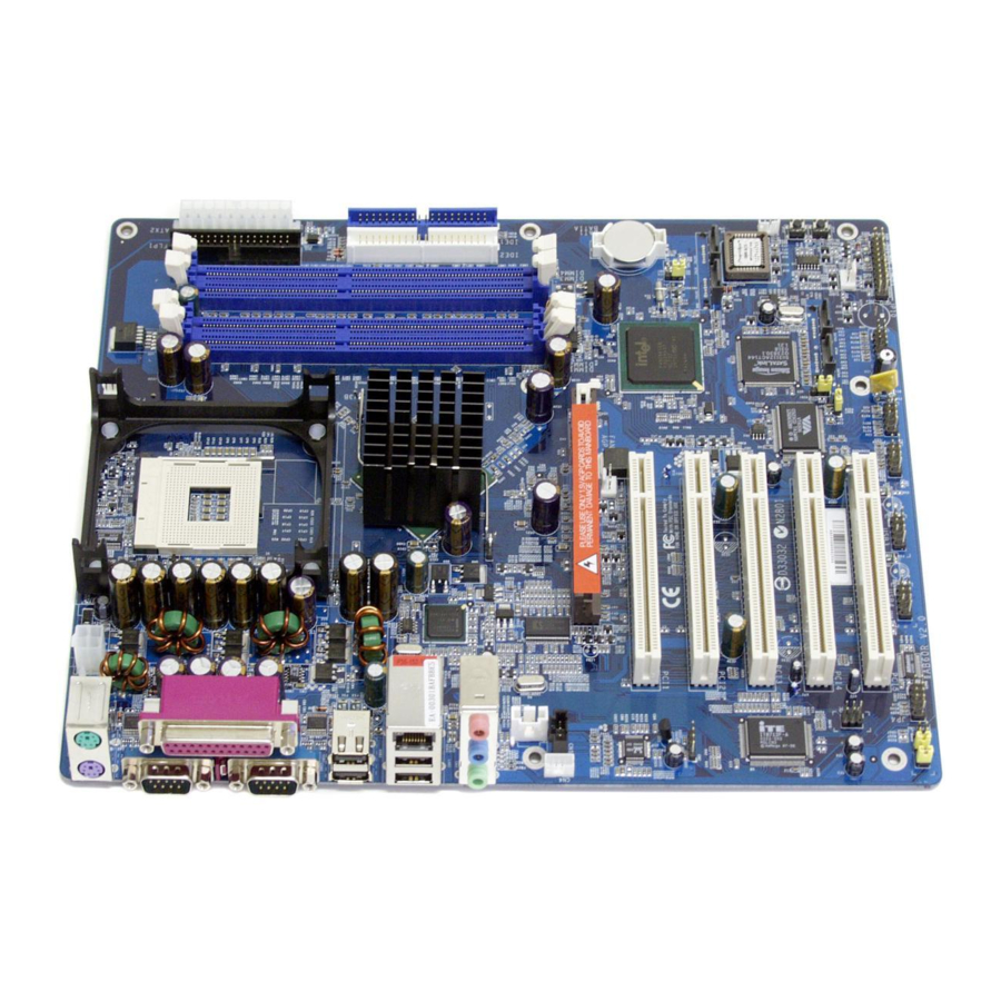
1.2 Item Checklist Check all items with your AB60/R mainboard to make sure nothing is miss- ing. The complete package should include: RichTek RT9173A CM53JK4 COM1 - One piece of Shuttle AB60/R Mainboard COM 2 USB 1 USB 2 CN 5... - Page 12 - I/O Shielding - AB60/R User's Manual - One piece of Bundled CD-ROM with containing: Ø AB60/R user's manual saved in PDF format Ø Intel Chipset Driver Ø Realteck Audio driver Ø SATA RAID driver (AB60R Only) Ø SiICfg Installation Utility(AB60R Only)
-
Page 13: Features
2 FEATURES AB60/R mainboard is carefully designed for the demanding PC user who wants high performance and maximum intelligent features in a compact package. 2.1 Specifications - CPU Support Intel Pentium 4 /Celeron, 478-pin processors with 400/533/800 MHz FSB. and CPU Voltage between 0.8375V~1.5875V. - Page 14 Ø 2 X Serial Ports. Ø 1 X Parallel Port.(SPP,EPP,ECP) Ø 1 X Line-Out port. Ø 1 X Line-In port. Ø 1 X Mic-In port. - PCI Bus Master IDE Controller Onboard Two Ultra DMA 100/66/33 Bus Master Dual-channel IDE ports provide sup- port to a maximum of four IDE devices (one Master and one Slave per channel).
- Page 15 Ø CPU Clock Setting - This item allows users to adjust CPU Host Clock in BIOS. Ø CPU Vcore Setting - This item allows users to adjust CPU Vcore in BIOS. Ø AGP Voltage Setting - This item allows users to select AGP Voltage in BIOS.
-
Page 16: Hardware Installation
Then follow these steps designed to guide you through a quick and correct installation of your system. 3.1 Step-by-Step Installation Accessories Of AB60/R Intel 865PE Chipset ATX 12V Power Connector - ATX2 CPU FAN - FAN1... -
Page 17: Step 1 Install The Cpu
Step 1 CPU Installation: This mainboard supports Intel Pentium 4/Celeron Socket 478 series CPU. Please follow the steps as follows to finish CPU installation. Note the CPU orientation when you plug it into CPU socket. 1. Pull up the CPU socket lever to 90-degree angle. CPU socket lever up to 90-degree angle 2. -
Page 18: Step 2 Set Jumpers
Step 2. Set Jumpers The default jumper settings have been set for the common usage standard of this mainboard. Therefore, you do not need to reset the jumpers unless you require special adjustments as any of the following cases: Clear CMOS IEEE1394 Setting (AB60R Only) RAID Setting (AB60R Only) For first-time DIY system builders, we recommend that you do not change the... -
Page 19: Step 4 Install Peripherals In System Case
Step 4 Install Internal Peripherals in System Case Before you install and connect the mainboard into your system case, we recommend that you first assemble all the internal peripheral devices into the computer housing, including but not limited to the hard disk drive (IDE/ HDD), floppy disk drive (FDD), CD-ROM drive, and ATX power supply unit. -
Page 20: Step 5 Mount The Mainboard On The Computer Chassis
Step 5 Mount the Mainboard on the Computer Chassis 1. You may find that there are a lot of different mounting hole positions both on your computer chassis and on the mainboard. To choose correct mounting holes, the key point is to keep the back-panel of the mainboard in a close fit with your system case, as shown below. -
Page 21: Step 6 Connect Front Panel Switches/Leds/Speaker/Usb
Step 6 Connect Front Panel Switches/LEDs/USB connectors You can find there are several different cables already existing in the system case and originating from the computer's front-panel devices (HDD LED, Power LED, Reset Switch, PC Speaker, or USB devices etc.) These cables serve to connect the front-panel switches, LEDs, and USB connectors to the mainboard's front-panel connectors group, as shown below. -
Page 22: Step 7 Connect Ide/ Floppy Disk/ Serial Ata Drives
Step 7 Connect IDE and Floppy Disk Drives 1. IDE cable connector 2. Floppy cable connector 3. Serial ATA Connectors (SATA1/SATA2)/ (SATA3/SATA4)(AB60R Only) - 18 -... -
Page 23: Step 8 Connect Other Internal Peripherals
Step 8 Connect Other Internal Peripherals 1. CD-IN, AUX-IN, Center/Bass audio headers AUX-IN CN 5 CD-IN CENTER/BASS CN 2 2. IR header 3. SPDIF In/Out header SPDIF In/Out JP 4 - 19 -... -
Page 24: Step 9 Connect The Power Supply
4. Front Panel Audio header Front Audio JP 3 Step 9 Connect the Power Supply 1. System power connector Step 10 Install Add-on Cards in Expansion Slots 1. Accelerated Graphics Port (AGP) Card 2. PCI Card - 20 -... -
Page 25: Step 11 Connect External Peripherals To Back Panel
Step 11 Connect External Peripherals to Back-Panel You are now ready to put the computer case back together and get on to the external peripherals connections to your system's back-panel. 1. PS/2 Mouse and PS/2 Keyboard 2. Parallel Port 3. COM1 Port 4. -
Page 26: Step 12 First Time System Boot Up
Step 12 First Time System Boot Up To assure the completeness and correctness of your system installation, you may check the above installation steps once again before you boot up your system for the first time. 1. Insert a bootable system floppy disk (DOS 6.2x, Windows 95/98/NT, or others) which contains FDISK and FORMAT utilities into the FDD. -
Page 27: Step 13 Install Drivers & Software Components
2000/ME/NT operating systems only. Make sure your operating system is already installed before running the drivers installation CD-ROM programs. 1. Insert the AB60/R bundled CD-ROM into your CD-ROM drive. The auto-run program will display the drivers main installation window on screen. -
Page 28: Jumper Settings
3.2 Jumper Settings Several hardware settings are made through the use of mini jumpers to con- nect jumper pins on the mainboard. Pin #1 could be located at any corner of each jumper, you just find the location with a white right angle which stands for pin 1#. -
Page 29: Jumpers & Connectors Guide
Jumpers & Connectors Guide Use the mainboard layout on page 11 to locate CPU socket, memory banks, expansion slots, jumpers and connectors on the mainboard during the instal- lation. The following list will help you to identify jumpers, slots, and connec- tors along with their assigned functions: B2~B4 B6~B7... -
Page 30: Jumpers
Jumpers : Clear CMOS setting : Disable IEEE1394 setting (AB60R Only) : Disable RAID setting(AB60R Only) Back Panel Connectors : PS/2 keyboard port : PS/2 mouse port Parallel : Printer port COM1 : Serial port COM2 : Serial port USB1/2 :2x USB ports :1x LAN port USB3/4... -
Page 31: Clear Cmos Setting (Jp2)
Other Connectors ATX1/ATX2 : ATX power connectors FAN1 : CPU fan connector FAN2 : AGP fan connector FAN3 : System fan connector : IR header CN4/CN5 : CD-IN 1/2 headers : AUX-IN header : Center/Bass audio header : Front Panel Audio header : SPDIF In/Out header USB3&USB4 : Extended USB Headers... -
Page 32: Disabled Ieee1394 Setting (Jp8)(Ab60R Only)
Disable IEEE1394 Setting (JP8) (AB60R Only) JP8 is used to enable/disable built-in IEEE1394 adapter. Pin 1-2 (Enable) Pin 2-3 (Disable) Disable RAID setting (JP9)(AB60R Only) JP9 is used to enable/disable built-in RAID adapter. Pin 1-2 (Enable) Pin 2-3 (Disable) 1 JP 9 - 28 -... -
Page 33: Back-Panel Connectors Ps/2 Keyboard & Ps/2 Mouse Connectors
Back-Panel Connectors PS/2 Keyboard & PS/2 Mouse Connectors Two 6-pin female PS/2 keyboard & Mouse connectors are located at the rear panel of PS/2 Mouse the mainboard. Depending on the com- puter housing you use (desktop or tower), the PS/2 Mouse connector is situated at the top of the PS/2 Keyboard connector when the mainboard is laid into a desktop, as op- posed to a tower where the PS/2 Mouse... -
Page 34: 10/100/1000 Base-T Lan Port Connector
LAN port 10/100/1000 base-T LAN Port Connector This mainboard can accommodate one device on LAN. Attach a Giga cable to the LAN port at the back-panel of your computer. USB3/USB4 Port Connectors USB port4 This mainboard offers 2 USB ports on back panel. -
Page 35: Front-Panel Connectors Hdd Led Connector (Hled)
Front-Panel Connectors HDD LED Connector (HLED) Attach the connector cable from the IDE device LED to the 2-pin (HLED) header. The HDD LED lights up whenever an IDE device is active. EPMI SPEAKER HLED JP 10 PWRON GLED PWRLED Hardware Reset Connector (RST) Attach the 2-pin hardware reset switch cable to the (RST) header. -
Page 36: Epmi Connector (Epmi)
EPMI Connector (EPMI) Hardware System Management Interface (EPMI) header may attach to 2-pin momentary switch. Press the switch to force system into power saving mode; press it again to resume back the normal operation situation. SPEAKER EPMI HLED JP 10 PWRON GLED PWRLED... -
Page 37: Green Led Connector (Gled)
Green LED Connector (GLED) The header is dual color LED function. Dual color LED function is defined by either Power LED or Green LED, the header can be in these states. The Green LED Indicates that the system in currently in one of the power saving mode(Doze/Standby/Suspend). -
Page 38: Power Led Connector (Pwrled)
Power LED Connector (PWRLED) Attach the 3-pin Power-LED connector cable from the housing front-panel to the (PWRLED) header on the mainboard. The power LED stays light while the system is running. EPMI SPEAKER HLED JP 10 PWRON GLED PWRLED Internal Peripherals Connectors Enhanced IDE and Floppy Connectors The mainboard features two 40-pin dual-channel IDE device connectors (IDE1/IDE2) providing support for up to four IDE devices, such as CD-ROM... -
Page 39: Other Connectors Atx Power Supply Connectors (Atx1&Atx2)
Other Connectors ATX Power Supply Connectors (ATX1&ATX2) This motherboard uses 20-pin Pentium 4 standard ATX power header, and ATX2 with 2x2-pin PC ATX power supply headers. Please make sure you plug in the right direction. ATX1 ATX2 Note 1: The ATX power connector is directional and will not go in unless the guides match perfectly making sure that pin#1 is properly positioned. -
Page 40: Cooling Fan Connectors For Cpu (Fan1), Agp (Fan2), System(Fan3)
CPU, AGP and System Fan connectors (FAN1/FAN2/FAN3) The mainboard provides four onboard 12V cooling fan power connectors to support CPU(FAN1) , AGP(FAN2) and System(Fan3) cooling fans. Note: Both cable wiring and type of plug may vary,which depends on the fan maker. Keep in mind that the FAN1 red wire should always be con- nected to the +12V header and... -
Page 41: Cd-In Connectors (Cn4/Cn5)
CD_IN Connectors (CN4/CN5) Port CN4/CN5 is used to attach an audio connector cable from the CD-ROM drive. CN4 Pins Assignment 1=XCDGND 2=XCDINR 3=XCDGND 4=XCDINL CN 5 CD-IN CN5 Pins Assignment 1=XCDINL 2=XCDGND 3=XCDGND 4=XCDINR Audio AUXILIARY_IN Connector (CN6) Port CN6 can be used to connect a stereo audio input from CD-ROM, TV-tuner or MPEG card. -
Page 42: Center/Bass_Out Header (Cn2)
Center/Bass_Out Header (CN2) CN2 header can be used to connect the cable which attached to center/bass amplified speakers. 1 2 3 4 Pin Assignments: 1=Center out 2=AGND 3=AGND CENTER/BASS 4=Bass out CN 2 Front Panel Audio Connector (JP3) This header allows the user to install auxiliary front-oriented micorophone and line-out ports for easier access. -
Page 43: Extended Usb Connector (Usb3/Usb4)
Extended USB Connector (USB3/USB4) The headers are used to connect the cable attached to USB connectors which are mounted on front-panel or back-panel. But the USB cable is optional at the time of purchase. USB 3 & USB4 Pins Assignment: 1=5VDUAL 2=5VDUAL 3=DATA3-... -
Page 44: Wol Connector (Wol1)
2=GND 3=SENSE 3.3 System Memory Configuration The AB60/R mainboard has four 184-pin DIMM slots that allow you to install from 64MB up to 4GB of system memory. Each 184-pin DIMM (Dual In-line Memory Module) Slot can accommodate 64MB, 128MB, 256MB, 512MB, and 1GB of PC2100, PC2700 or PC3200 compliant 2.5V single (1 Bank) or double (2 Bank) side 64-bit wide data path... -
Page 45: Upgrade Memory
Dual channel memory controller configuration: All the other case: 1.Running in Dual Channel Mode The DIMM must be the same memory size and the same type to let this function work. DIMM1 DIMM2 DIMM2 DIMM1 DIMM1 DIMM2 CH A CH A CH A CH B CH B... -
Page 46: Software Utility
4 SOFTWARE UTILITY 4.1 Mainboard CD Overview Note: The CD contents attached in AB60/R mainboard are subject to change without notice. To start your mainboard CD disc, just insert it into your CD-ROM drive and the CD AutoRun screen should appear. If the AutoRun screen does not appear, double click or run D:\Autorun.exe (assuming that your CD-ROM... - Page 47 Insert the attached CD into your CD-ROM drive and the CD AutoRun screen should appear. If the AutoRun screen does not appear, double click on Autorun icon in My Computer to bring up Shuttle Mainboard Software Setup screen. Select using your pointing device (e.g. mouse) on the "Install Mainboard AB60/R Software"...
-
Page 48: A Install Intel Chipset Driver
4.2.A Install Chipset System Driver Select using your pointing device (e.g. mouse) on the "Install Intel Chipset Driver" bar to install chipset system driver. Once you made your se- lection, a Setup window run the installation automatically. When the copying files is done, make sure you reboot the system to take the installation... -
Page 49: C Install Audio Driver
Insert the attached CD into your CD-ROM drive and the CD AutoRun screen should appear. If the AutoRun screen does not appear, double click on Autorun icon in My Computer to bring up Shuttle Mainboard Software Setup screen. Select using your pointing device (e.g. mouse) on the “Install Intel LAN Driver”... -
Page 50: E Install Raid Driver (Ab60R Only)
4.2.E Install RAID Driver (AB60R Only) Select using your pointing device (e.g. mouse) on the “Install RAID Driver " bar to install RAID driver. Once you made your selection, a Setup window run the installation automatically. When the copying files is done, make sure you reboot the system to take the installation effect. -
Page 51: View The User's Manual
Insert the attached CD into your CD-ROM drive and the CD AutoRun screen should appear. If the AutoRun screen does not appear, double click on AutoRun icon in My Computer to bring up Shuttle Mainboard Software Setup screen. Select using your pointing device (e.g. mouse) on the “Manual" bar. -
Page 52: Bios Setup
5 BIOS SETUP AB60/R BIOS ROM has a built-in Setup program that allows users to modify the basic system configuration. This information is stored in battery-backed RAM so that it retains the Setup information even if the system power is turned off. -
Page 53: The Main Menu
5.2 The Main Menu Once you enter the AwardBIOS(tm) CMOS Setup Utility, the Main Menu will appear on the screen. The Main Menu allows you to select from several setup functions and two exit choices. Use the arrow keys to select among the items and press <Enter> to accept and enter the sub-menu. - Page 54 PnP / PCI Configurations This entry appears if your system supports PnP / PCI. PC Health Status This entry shows the current system temperature, Voltage, and FAN speed. Frequency/Voltage Control Use this menu to specify your settings for frequency/voltage control. Load Fail-Safe Defaults Use this menu to load the BIOS default values for the minimal/stable performance of your system to operate.
-
Page 55: Standard Cmos Features
Standard CMOS Features The items in Standard CMOS Setup Menu are divided into 10 catego- ries. Each category includes no, one or more than one setup items. Use the arrow keys to highlight the item and then use the <PgUp> or <PgDn>... - Page 56 IDE Channel 1 Slave Options are in its sub menu. Press <Enter> to enter the sub-menu of detailed options. Drive A/Drive B Select the type of floppy disk drive installed in your system. Ø The choice: None, 360K, 5.25 in, 1.2M, 5.25 in, 720K, 3.5 in, 1.44M, 3.5 in, or 2.88M, 3.5 in.
- Page 57 IDE HDD Auto-Detection Press <Enter> to auto-detect HDD on this channel. If detection is successful, it fills the remaining fields on this menu. Ø Press Enter IDE Primary Master Selecting 'manual' lets you set the remaining fields on this screen and select the type of fixed disk.
-
Page 58: Advanced Bios Features
Advanced BIOS Features This section allows you to configure your system for basic operation. You have the opportunity to select the system's default speed, boot-up sequence, keyboard operation, shadowing, and security. Hard Disk Boot Priority This item allows you to select Hard Disk Boot Device Priority. BIOS Write Protect This item allows you to enable or disable the BIOS Write Protect. - Page 59 CPU L1&L2 Cache All processors that can be installed in this mainboard use internal level1(L1) and external 2(L2) cache memory to imporve performance. Leave this item at the default value for better performance. Ø The choice: Enabled or Disabled. Hyper-Threading Technology This item allows you to enable or disable CPU Hyper-Threading func- tion.
- Page 60 Gate A20 Option This entry allows you to select how the gate A20 is handled. The gate A20 is a device used for above 1MBye of address memory. Initially, the gate A20 was handled via a pin on the keyboard. Today, while a keyboard still provides this support, it is more common and much faster in setting to Fast for the system chipset to provide support for gate A20.
- Page 61 MPS Version Control For OS Selects the operating system multiprocessor support version. Ø The choice: 1.1 or 1.4 OS Select For DRAM > 64MB Selects the operating system that is running with greater than 64MB of RAM in the system. Ø...
-
Page 62: Advanced Chipset Features
Advanced Chipset Features This section allows you to configure the system based on the specific features of the installed chipset. This chipset manages bus speeds and access to sys- tem memory resources, such as DRAM and the external cache. It also coor- dinates communications between the conventional ISA bus and the PCI bus. - Page 63 DRAM RAS# to CAS# Delay This field lets you insert a timing delay between the CAS and RAS strobe signals, and you can use it when DRAM is written to, read from, or refreshed. Faster performance is gained in high speed, more stable performance, in low speed.
- Page 64 Delay Prior to Thermal This item select the Delay time before thermal controller activate from temperature too high. Ø The Choice: 4 Min, 8 Min, 16 Min, or 32 Min. AGP Aperture Size (MB) Select the size of Accelerated Graphics Port (AGP) aperture. The aper- ture is a portion of the PCI memory address range dedicated to graphics memory address space.
-
Page 65: Integrated Peripherals
Integrated Peripherals These options display items that define the operation of peripheral comopnents on the system's input/output ports. On-Chip IDE Device Options are in its sub-menu. Press<Enter> to enter the sub-menu of details options. IDE HDD Block Mode Block mode is also called block transfer, multiple commands, or mul- tiple sector read/write. - Page 66 IDE Master/Slave UDMA Ultra DMA 100 implementation is possible only if your IDE hard drive supports it and the operating environment includes a DMA driver (Windows 95 OSR2 or a third-party IDE bus master driver). If both of your hard drive and your system software support Ultra UMA100, select Auto to enable BIOS support.
- Page 67 Disabled : Disabled SATA Controller. Serial ATA 1 Disable Serial ATA 2 (Channel 0) IDE1 Master Slave (Channel 1) IDE2 Master Slave Auto: Auto arrange by BIOS. Combined Mode:PATA and SATA are combined. Max. of 4 ATA drives are supported. (DOS,Win2K,Win98/ME...) should set SATA and PATA to Combined Mode.
- Page 68 (Channel 1) Serial ATA 1 Serial ATA 1 (Channel 1) Master Slave Secondary Secondary Master Slave (Channel 1) Serial ATA 2 Serial ATA 2 (Channel 1) (Channel 0) (Channel 0) IDE1 IDE1 Master Master Primary Primary Slave Slave IDE2 IDE2 Disable Disable Combin 4...
- Page 69 SATA-Only:SATA is operating in legacy mode. Serial ATA 1 (Channel 0) Primary Master or Secondary (Channel 1) Serial ATA 2 (Channel 1) Secondary Master or Primary (Channel 0) IDE1 Disable IDE2 Disable Serial ATA Port0/1 Mode This item allows you to set the Serial ATA Port mode. Ø...
- Page 70 AC97 Audio Enables and disables the onboard audio chip. Disable this item if you are going to install a PCI audio add-on card. Ø The choice: Auto or Disabled. Silicon Image Raid ROM This item is used to enable/disable Silicon Image RAID ROM. Ø...
-
Page 71: Power Management Setup
Power Management Setup The Power Management Setup allows you to configure your system to most effectively saving energy while operating in a manner consistent with your own style of computer use. ACPI Function This item allows you to enable/disable the Advanced Configuration and Power Management (ACPI) Ø... - Page 72 Max Saving Maximum power management. Suspend Mode=1min. HDD Power Down=1min. User Define Allows you to set each mode individually. When this item not disabled, each of the ranges are from 1 min. to 1 hr. except for HDD Power Down which ranges from 1 min.
- Page 73 Soft-Off by PWR-BTTN Pressing the power button for more than 4 seconds forces the system to enter the Soft-Off state when the system has "hung.". Ø The choice: Instant-Off or Delay 4 Sec. Wake-Up by PCI card This item Enabled/Disabled PCI card wakeup for PCI Spec 2.2. Ø...
- Page 74 [mm/ss] Ø Key in a DEC number:Min=0, Max=59. *** Reload Global Timer Events *** Primary/Secondary IDE0/1 When these items are enabled, the system will restart the power-saving timeout counters when any activity is detected on any of the drivers or devices on the primary or secondary IDE channels.
-
Page 75: Pnp/Pci Configuration
PnP/PCI Configurations This section describes the configuration of PCI bus system. PCI or Personal Computer Interconnection is a system which allows I/O devices to operate at the speed CPU itself keeps when CPU communicating with its own special components. This section covers some very technical items, and it is strongly recommended that only experienced users should make any changes to the default settings. - Page 76 IRQ3/4/5/7/9/10/11/12/14/15 assigned This item allows you to determine the IRQ assigned to the ISA bus and is not available to any PCI slot. Legacy ISA for devices is compliant with the original PC AT bus specification; PCI/ISA PnP for devices is compli- ant with the Plug-and-Play standard whether designed for PCI or ISA bus architecture.
-
Page 77: Pc Health Status
PC Health Status Shutdown Temperature Enables you to set the maximum temperature the system can reach before powering down. Ø The choice: Disabled, 60 C/140 F, 65 C/149 F, 70 C/158 F or C/167 System Component Characteristics These fields provide you with information about the systems current operating status. -
Page 78: Frequency/Voltage Control
Frequency/Voltage Control This iteme enables you to set the clock speed and system bus for your system. The clock speed and system bus are determine by the kind of processor youhave installed in your system. CPU Clock Ratio This item allows you to adjust CPU Ratio. Ø... -
Page 79: Load Fail-Safe Defaults
Async AGP/PCI CLK This item allows . Ø The choice: Sync by CPU Clock , fixed 66/33/100MHz, fixed 73/ 36/100MHz or fixed 80/40/100MHz. CPU Voltage This item allows .you to adjust the CPU Voltage. Ø The choice: Default ,0.8250~1.5875V. DDR Voltage This item allows .you to adjust the DDR Voltage Ø... -
Page 80: Set Supervisor/ User Password
Supervisor/User Password Setting You can set either supervisor or user password, or both of them. The differences between them are: Supervisor Password and User Password The options on the Password screen menu make it possible to restrict access to the Setup program by enabling you to set passwords for two different access modes: Supervisor mode and User mode. -
Page 81: Save & Exit Setup
Password Disable If you select System at Security Option of BIOS Features Setup Menu, you will be prompted in entering the password whenever the system is rebooted or you try to enter Setup. If you select Setup at Security Option of BIOS Features Setup Menu, you will be prompted only when you try to enter Setup.
Need help?
Do you have a question about the AB60/R and is the answer not in the manual?
Questions and answers