Table of Contents
Advertisement
Quick Links
3-phase motor control demonstration board featuring IGBT
Introduction
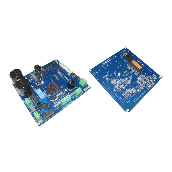
This document describes the 1 kW 3-phase motor control demonstration board, featuring
the STGIPS10K60A: 600 V - 10 A IGBT Intelligent power module. The demonstration board
is a 3-phase inverter for driving an induction motor or PMSM motors up to 1000 W. The main
target of this application is to show users the performance of the ST 25L-SDIP (25-lead,
small dual inline package), IPM - STGIPS10K60A.
The board has been designed to be compatible with a single-phase supply from 90 VAC to
220 VAC, or for DC voltage from 125 VDC to 350 VDC. The document is associated with the
release of the STEVAL-IHM027V1 demonstration board (see
Figure 1.
STEVAL-IHM027V1 demonstration board
November 2010
intelligent power module STGIPS10K60A
Doc ID 17665 Rev 1
UM0969
User manual
Figure
1).
1/57
www.st.com
Advertisement
Table of Contents

Related Manuals for ST UM0969


Summary of Contents for ST UM0969
-
Page 1: Figure 1. Steval-Ihm027V1 Demonstration Board
3-phase inverter for driving an induction motor or PMSM motors up to 1000 W. The main target of this application is to show users the performance of the ST 25L-SDIP (25-lead, small dual inline package), IPM - STGIPS10K60A. -
Page 2: Table Of Contents
Contents UM0969 Contents System introduction ......... 6 Main characteristics . - Page 3 UM0969 Contents Power losses and dissipation ....... . 44 Assumptions ..........44 Conduction loss .
- Page 4 List of tables UM0969 List of tables Table 1. Jumper settings for a single-shunt or three-shunt configuration ..... 24 Table 2.
- Page 5 UM0969 List of figures List of figures Figure 1. STEVAL-IHM027V1 demonstration board ........1 Figure 2.
-
Page 6: System Introduction
● +15 V auxiliary power supply based on buck converter with VIPer16 ● Fully populated board conception with testing points ● Motor control connector for interface with STM3210B-EVAL board and further ST motor control dedicated kits ● Tachometer input ●... -
Page 7: Safety And Operating Instructions
UM0969 System introduction Safety and operating instructions 1.3.1 General terms Warning: During assembly, testing, and normal operation, the demonstration board poses several inherent hazards, including bare wires, moving or rotating parts and hot surfaces. There is a danger of serious personal injury if the kit or components are improperly used or incorrectly installed. -
Page 8: Electrical Connections
System introduction UM0969 1.3.4 Electrical connections Applicable national accident prevention rules must be followed when working on the main power supply with a motor drive. The electrical installation must be completed in accordance with the appropriate requirements. A system architecture which supplies power to the demonstration board must be equipped with additional control and protective devices in accordance with the applicable safety requirements (e.g. -
Page 9: Board Description
Control block: the main task of this block is to accept user commands and board\motor configuration parameters. The control block provides all digital signals to implement the right motor driving strategy. The STM3210B-EVAL, ST demonstration board, based on an STM32 microcontroller, can be connected to the STEVAL-IHM027V1 thanks to the onboard motor control connector ●... -
Page 10: Board Schematics
Board schematics Figure 3. Input stage with bridge schematic... -
Page 11: Figure 4. Bus Voltage Sense Resistor Schematic
UM0969 Board description Figure 4. Bus voltage sense resistor schematic Figure 5. +5 V linear schematic Doc ID 17665 Rev 1 11/57... -
Page 12: Figure 6. +3.3 V Linear Schematic
Board description UM0969 Figure 6. +3.3 V linear schematic Figure 7. Buck converter schematic 12/57 Doc ID 17665 Rev 1... -
Page 13: Figure 8. Thermal Shutdown
UM0969 Board description Figure 8. Thermal shutdown Doc ID 17665 Rev 1 13/57... -
Page 14: Figure 9. Ntc Bypass Schematic
Board description UM0969 Figure 9. NTC bypass schematic Figure 10. Motor output schematic 14/57 Doc ID 17665 Rev 1... -
Page 15: Figure 11. +15 V Auxiliary Supply Schematic
UM0969 Board description Figure 11. +15 V auxiliary supply schematic Figure 12. BEMF_daughter board schematic Figure 13. Motor control connector schematic Doc ID 17665 Rev 1 15/57... -
Page 16: Figure 14. Hall Sensors\Encoder Schematic
Board description UM0969 Figure 14. Hall sensors\encoder schematic Figure 15. Tachometer sensor schematic 16/57 Doc ID 17665 Rev 1... -
Page 17: Figure 16. Brake Control Schematic
Figure 16. Brake control schematic... -
Page 18: Figure 17. Steval-Ihm027V1 Schematic
Board description UM0969 Figure 17. STEVAL-IHM027V1 schematic Figure 18. Current sensing A schematic 18/57 Doc ID 17665 Rev 1... -
Page 19: Figure 19. Current Sensing B Schematic
UM0969 Board description Figure 19. Current sensing B schematic Figure 20. Current sensing C schematic Doc ID 17665 Rev 1 19/57... -
Page 20: Figure 21. Overcurrent\Overtemperature Protection Schematic
Figure 21. Overcurrent\overtemperature protection schematic... -
Page 21: Circuit Description
UM0969 Board description Circuit description 2.3.1 Power supply Power supply of the STEVAL-IHM027V1 is realized as a multifunctional block which allows the inverter to be supplied up to +350 V. The auxiliary power supply, needed for the active components on the demonstration board, is implemented with a buck converter based on U10 VIPer16, which works with a fixed frequency of 60 kHz. -
Page 22: Overcurrent Protection (Ocp)
Board description UM0969 The brake function can be also activated by the microcontroller thanks to the motor control connector (connector J3, pin 23 PWM_BRAKE signal). The brake threshold levels can be modified by calculating R83, R85, and R86 new values. - Page 23 UM0969 Board description Default values for the STEVAL-IHM027V1 are: ● r = 1 kΩ (R11, R25, R30) ● R = 5.4 kΩ (R12-13, R21-22, R31-32) R1 = 560 Ω (R4, R15, R27) ● R2 = 560 Ω (R7, R18, R28) ●...
-
Page 24: Table 1. Jumper Settings For A Single-Shunt Or Three-Shunt Configuration
Board description UM0969 Six-step (block commutation) current reading configuration In the case of six-step (also called block commutation) current control, only two motor phases conduct current at the same time. Therefore, it is possible to use only one shunt resistor. Moreover, as the current flows always in the same direction, only a positive value has to be measured. -
Page 25: Tachometer And Hall/Encoder Input
UM0969 Board description The op amp is used in follower mode and its gain can be set by resistor r and R: Equation 6 (op amp output voltage) can be calculated as a sum of two components: ● : due to network polarization BIAS ●... -
Page 26: Table 2. Internal Ipm Ntc Details (See Relevant Section On The Stgips10K60A Datasheet)
Board description UM0969 The STEVAL-IHM027V1 includes a hardware OT protection that stops the PWM signal path from the MCU to STGIPS10K60A logic input once the maximum allowable temperature is passed. With the chosen value, the OT protection limit is set to 70 °C. Another suggested scheme, generally adopted for temperature monitoring and protection, is shown in . -
Page 27: Hardware Setting Of The Steval-Ihm027V1
UM0969 Hardware setting of the STEVAL-IHM027V1 Hardware setting of the STEVAL-IHM027V1 The STEVAL-IHM027V1 demonstration board can be driven through the J3 motor connector by various control units released by STMicroelectronics. The demonstration board is suitable for field oriented control as well as for tachometer or Hall sensor closed-loop control. -
Page 28: Hardware Settings With Three-Shunt Configuration
Hardware setting of the STEVAL-IHM027V1 UM0969 Table 3. Jumper settings for single-shunt configuration (continued) Settings for single-shunt configuration Jumper HV PMSM motor Generic AC motor with tachometer User defined User defined User defined User defined Hardware settings with three-shunt configuration To drive any high PMSM or AC induction motor, the user must ensure that: ●... -
Page 29: Hardware Settings For Input Stage
UM0969 Hardware setting of the STEVAL-IHM027V1 Hardware settings for input stage The input stage of the STEVAL-IHM027V1 can be configured according to user needs (see Figure 26 ). Please refer to Table 5 for detailed information. Figure 26. STEVAL-IHM027V1 input stage detail Table 5. -
Page 30: Description Of Jumpers, Test Pins, And Connectors
Description of jumpers, test pins, and connectors UM0969 Description of jumpers, test pins, and connectors The following tables give a detailed description of the jumpers, test pins, and the pinout of the connectors used. Table 6 gives a detailed description of the jumpers. - Page 31 UM0969 Description of jumpers, test pins, and connectors Table 6. Jumpers description (continued) Jumper Selection Description Present GIPS10K60A NTC signal enabled Not present GIPS10K60A NTC signal disabled A position “OCP” and “OTP” protection enabled B position “OCP” and “OTP” protection disabled Table 7.
-
Page 32: Table 7. Connector Pinout Description
Description of jumpers, test pins, and connectors UM0969 Table 7. Connector pinout description (continued) Name Reference DEscription\pinout otor control connector 1 - emergency stop 2 - GND 3 - PWM - 1H 4 - GND 5 - PWM-1L 6 - GND 7 - PWM-2H... - Page 33 UM0969 Description of jumpers, test pins, and connectors Table 7. Connector pinout description (continued) Name Reference DEscription\pinout BEMF daughter board connector 1 - phase A 2 - phase B 3 - phase C 4 - bus voltage 5 - 3.3 VDC...
-
Page 34: Table 8. Testing Points Description
Description of jumpers, test pins, and connectors UM0969 Table 8. Testing points description Test point Description Phase A Phase B Phase C PWM – phase A – low side PWM – phase A – high side PWM – phase B – low side PWM –... -
Page 35: Connector Placement
UM0969 Connector placement Connector placement A basic description of the placement of all connectors on the board is visible in Figure 27 Figure 27. Connector placement Doc ID 17665 Rev 1 35/57... -
Page 36: Bom List
BOM list A list of components used to build the demonstration board is shown in Table 9 . The majority of the active components used are available from STMicroelectronics. Table 9. BOM list Reference Value/part number Package Manufacturer C1, C54 4.7 µF/10 V Elyt. - Page 37 Table 9. BOM list (continued) Reference Value/part number Package Manufacturer D1,D2,D3,D4,D5,D6,D7,D8,D16,D19 BAR43 SOT23 STMicroelectronics STTH1L06A SMD 1206 STMicroelectronics D18,D21 1N4148 DO35 KBU6M Diode Bridge,250 VAC, 6 A BZX84C18 MiniMelf BZX85C16 MiniMelf STTH1L06 DO-41 STMicroelectronics STTH108 DO-41 STMicroelectronics D17,D20 BZX84C13V MiniMelf F1,F2 Fuse holder 5x20 mm...
- Page 38 Table 9. BOM list (continued) Reference Value/part number Package Manufacturer R17,R83 2.2 kΩ SMD 1206 R23,R99 5.6 kΩ SMD 1206 22 Ω SMD 1206 R33,R35,R36,R44,R49,R76,R79R84 10 kΩ SMD 1206 100 Ω R37,R54,R56,R69,R70,R71,R75R78 SMD 1206 R38,R39,R40,R41,R42,R43,R92 47 kΩ SMD 1206 R45,R95 68 kΩ...
- Page 39 Table 9. BOM list (continued) Reference Value/part number Package Manufacturer TSV944 SO-14 STMicroelectronics M74HC08 SO-14 STMicroelectronics M74HC367M1R SO-16 STMicroelectronics LD1117D33 SO-8 STMicroelectronics U6,U8 TS391ILT SOT23-5 STMicroelectronics RELAY10A RELAY Finder STGIPS10K60A SSDIP-25L STMicroelectronics VIPER16LN SO-16 STMicroelectronics...
-
Page 40: Pcb Layout
PCB layout UM0969 PCB layout For this application a standard, double-layer, coppered PCB with a ~45 µm copper thickness was selected. The PCB material is FR-4. The dimensions of the board are: ● Length: 147 mm ● Width: 157 mm ●... -
Page 41: Figure 29. Copper Tracks - Bottom Side
UM0969 PCB layout Figure 29. Copper tracks - bottom side Doc ID 17665 Rev 1 41/57... -
Page 42: Figure 30. Silk Screen - Top Side
PCB layout UM0969 Figure 30. Silk screen - top side 42/57 Doc ID 17665 Rev 1... -
Page 43: Figure 31. Silk Screen - Bottom Side
UM0969 PCB layout Figure 31. Silk screen - bottom side Doc ID 17665 Rev 1 43/57... -
Page 44: Power Losses And Dissipation
Power losses and dissipation UM0969 Power losses and dissipation The power dissipation of the IPM, during normal working, is due to the conduction and switching losses of IGBTs and diodes. The losses during the turn-off steady-state can be ignored, because of their very small amount, and because of the minor effect of increasing the temperature in the device. -
Page 45: Figure 32. Static Parameter Calculations
UM0969 Power losses and dissipation Figure 32 shows how to calculate the relevant parameters (values reported are not referred to the STGIPS10K60A). Figure 32. Static parameter calculations = ΔV / ΔI ΔI = ΔV / ΔI ΔI ΔV ΔV AM07753v1 Assuming that the switching frequency is high, the output current of the PWM-inverter can be assumed to be sinusoidal. -
Page 46: Switching Loss
Power losses and dissipation UM0969 Equation 14 ε θ cos( and m is the PWM modulation index (defined as the peak phase voltage divided by the half of dc link voltage). Finally, the integration of gives: Equation 12 Equation 13 Equation 15 It should be noted that the total IPM conduction losses are six times the calculated Pcon. -
Page 47: Table 10. Rc - Cauer Stgips10K60A Thermal Network
UM0969 Power losses and dissipation fundamental) concept of thermal resistance must be considered, which is defined as the difference in temperature between two closed isothermal surfaces divided by the total power flow between them, Equation 18 Equation 18 For semiconductor devices, typically, the important factors are the relation between T... -
Page 48: Temperature Rise Considerations And Calculation Example
Power losses and dissipation UM0969 Table 10. RC - Cauer STGIPS10K60A thermal network (continued) RC - Cauer STGIPS10K60A thermal network Value [ºC/W] Value [W*s/ºC] 0.432 1.20E-2 0.0123 0.149E-2 0.448 0.809E-3 1.66 0.120 Temperature rise considerations and calculation example According to the previous mathematical formula, it is possible to simulate (with an accurate software tool) the STGIPS10K60A performances, under certain application conditions. -
Page 49: Ordering Information
UM0969 Ordering information Ordering information The demonstration board is available through the standard ordering system, the order code is: STEVAL-IHM027V1. The items delivered include the assembled board, board documentation, PCB fabrication data such as gerber files, assembly files (pick and place), and component documentation. -
Page 50: Using The Steval-Ihm027V1 With Stm32 Foc Firmware Library
Using the STEVAL-IHM027V1 with STM32 FOC firmware library UM0969 Using the STEVAL-IHM027V1 with STM32 FOC firmware library The STM32 FOC firmware library v2.0 is a firmware library running on the STM3210B- MCKIT which allows the performing of the FOC of a PMSM (or ACIM) in a configuration with and without sensors. -
Page 51: Environmental Considerations
UM0969 Environmental considerations Environmental considerations Warning: The STEVAL-IHM027V1 demonstration board must only be used in a power laboratory. The voltage used in the drive system presents a shock hazard. The kit is not electrically isolated from the DC input. This topology is very common in motor drives. -
Page 52: Hardware Requirements
Hardware requirements UM0969 Hardware requirements To run the STEVAL-IHM027V1 together with the STM32 FOC firmware library, the following items are required: ● The board: STEVAL-IHM027V1 ● High voltage insulated AC power supply up to 230 VAC ● J-link programmer (not included in the package) ●... -
Page 53: Software Requirements
UM0969 Software requirements Software requirements To customize, compile, and download the STM32 FOC firmware library v2.0 motor control firmware, the IAR tool “EWARM v5.30” must be installed. The free 32 kB limited version (referenced as “IAR Kickstand Kit™” version) is available for download at http://supp.iar.com/Download. -
Page 54: Conclusion
Conclusion UM0969 Conclusion This document describes the 1 kW 3-phase motor control STEVAL-IHM027V1 demonstration board based on IPM as a universal fully-evaluated platform. 54/57 Doc ID 17665 Rev 1... -
Page 55: References
UM0969 References References STGIPS10K60A datasheet VIPer16 datasheet STGF10NC60KD datasheet UM0379 UM0723 Doc ID 17665 Rev 1 55/57... -
Page 56: Revision History
Revision history UM0969 Revision history Table 11. Document revision history Date Revision Changes 08-Nov-2010 Initial release. 56/57 Doc ID 17665 Rev 1... - Page 57 No license, express or implied, by estoppel or otherwise, to any intellectual property rights is granted under this document. If any part of this document refers to any third party products or services it shall not be deemed a license grant by ST for the use of such third party products or services, or any intellectual property contained therein or considered as a warranty covering the use in any manner whatsoever of such third party products or services or any intellectual property contained therein.
Need help?
Do you have a question about the UM0969 and is the answer not in the manual?
Questions and answers