Table of Contents
Advertisement
Quick Links
UM0920
User manual
4 W non-isolated, wide input-voltage range SMPS demonstration
board based on the VIPer16
Introduction
The purpose of this document is to provide information for the STEVAL-ISA071V2 switched
mode power supply (SMPS) demonstration board. The STEVAL-ISA071V2 is a non-isolated
SMPS capable of delivering a 4 W output over a wide input voltage range, and is designed
for a mains application requiring -5 V and +7 V, referred to neutral. The basic concepts used
in this design can also be applied for higher power outputs or different voltage ranges.
The SMPS generates outputs of 5 V and 12 V, referred to the output marked -5 V. The 5 V is
dedicated to supplying an MCU. This configuration allows the use of the MCU to directly
drive a Triac (referred to neutral). The 12 V output is used to supply additional circuits
(relays, OA, etc.).
This document contains a fundamental technical description of the demonstration board
(schematic diagram, PCB details and bill of materials) and basic measurements (load
regulation, efficiency, standby behavior and EMI data).
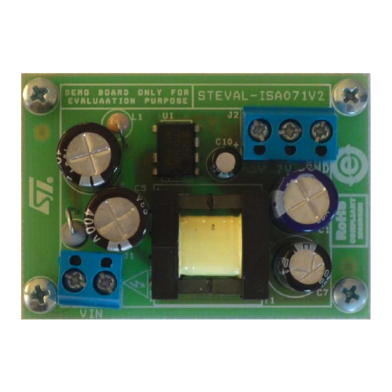
Figure 1.
STEVAL-ISA071V2 board
May 2012
Doc ID 17220 Rev 2
1/14
www.st.com
Arrow.com.
Downloaded from
Advertisement
Table of Contents

Related Manuals for ST UM0920


Summary of Contents for ST UM0920
-
Page 1: Figure 1. Steval-Isa071V2 Board
UM0920 User manual 4 W non-isolated, wide input-voltage range SMPS demonstration board based on the VIPer16 Introduction The purpose of this document is to provide information for the STEVAL-ISA071V2 switched mode power supply (SMPS) demonstration board. The STEVAL-ISA071V2 is a non-isolated SMPS capable of delivering a 4 W output over a wide input voltage range, and is designed for a mains application requiring -5 V and +7 V, referred to neutral. -
Page 2: Table Of Contents
Contents UM0920 Contents Main characteristics ......... 4 Board connections . - Page 3 UM0920 List of figures List of figures Figure 1. STEVAL-ISA071V2 board ..........1 Figure 2.
-
Page 4: Main Characteristics
Main characteristics UM0920 Main characteristics ● Input: – : 85 - 264 V – f: 45 - 66 Hz ● Output: – 12 VDC ± 10% (referred to -5 V), 160 mA – -5 VDC ± 4%, 400 mA –... -
Page 5: Board Connections
UM0920 Board connections Board connections The STEVAL-ISA071V2 demonstration board is pictured in Figure 2 below, with input and output locations. Figure 2. Input/output connection of SMPS Doc ID 17220 Rev 2 5/14 Arrow.com. Arrow.com. Arrow.com. Arrow.com. Arrow.com. Downloaded from Downloaded from... -
Page 6: Board Details
Board details UM0920 Board details Schematic diagram A schematic diagram of the non-isolated flyback converter board prototype based on the VIPer16 is provided in Figure 3 below. Figure 3. STEVAL-ISA071V2 circuit schematic 6/14 Doc ID 17220 Rev 2 Arrow.com. Arrow.com. -
Page 7: Description Of Main Components
UM0920 Board details Description of main components The complete converter application consists of an input section and the flyback converter itself. The input section contains: – Single diode rectifier (D3, D6) The single diode rectifier is selected to allow simple connection of neutral to GND and reduce components count. -
Page 8: Transformer
Board details UM0920 Transformer The transformer was developed in cooperation with EPCOS and is available through order number T5684-51-01. The transformer specification is as follows: – E16/8/5 - 60 kHz, voltage range 85 VAC - 264 VAC – Core shape E16/8/5 –... -
Page 9: Figure 4. Pcb Layout - Top Layer, Bottom Smd Layer And Bottom Copper Layer
UM0920 Board details Figure 4. PCB layout - top layer, bottom SMD layer and bottom copper layer Doc ID 17220 Rev 2 9/14 Arrow.com. Arrow.com. Arrow.com. Arrow.com. Arrow.com. Arrow.com. Arrow.com. Arrow.com. Arrow.com. Downloaded from Downloaded from Downloaded from Downloaded from... -
Page 10: Bill Of Materials
Board details UM0920 Bill of materials Table 2. Bill of materials Value / generic part Number Quantity Ref. Package / class Manufacturer number 22 Ω / 2 W / 5% R2, R7 200 kΩ / 5% 1206 4.7 kΩ / 1% / 0.1 W 0805 4.7 kΩ... -
Page 11: Measurements
UM0920 Measurements Measurements The basic measurements for efficiency, load characteristics and conductive EMI are shown Figure Figure Figure 7 Figure Figure 5. Efficiency at 120 VAC and 230 VAC Standby at 120 VAC: 20 mW Standby at 230 VAC: 35 mW 90.00... -
Page 12: Figure 7. Emi Measurement For En55022 Class B - Avg Detector
Measurements UM0920 Figure 7. EMI measurement for EN55022 Class B - AVG detector Figure 8. EMI measurement for EN55022 Class B - peak detector 12/14 Doc ID 17220 Rev 2 Arrow.com. Arrow.com. Arrow.com. Arrow.com. Arrow.com. Arrow.com. Arrow.com. Arrow.com. Arrow.com. Arrow.com. -
Page 13: Revision History
UM0920 Revision history Revision history Table 3. Document revision history Date Revision Changes 28-Jun-2010 Initial release. Replaced STEVAL-ISA071V1 by STEVAL-ISA071V2, updated 03-May-2012 Figure 1 Figure 4 and Disclaimer, minor text corrections throughout document. Doc ID 17220 Rev 2 13/14 Arrow.com. - Page 14 No license, express or implied, by estoppel or otherwise, to any intellectual property rights is granted under this document. If any part of this document refers to any third party products or services it shall not be deemed a license grant by ST for the use of such third party products or services, or any intellectual property contained therein or considered as a warranty covering the use in any manner whatsoever of such third party products or services or any intellectual property contained therein.
Need help?
Do you have a question about the UM0920 and is the answer not in the manual?
Questions and answers