Table of Contents
Advertisement
Quick Links
UM2711
User manual
Getting started with the STSW-ROBOT-1
Introduction
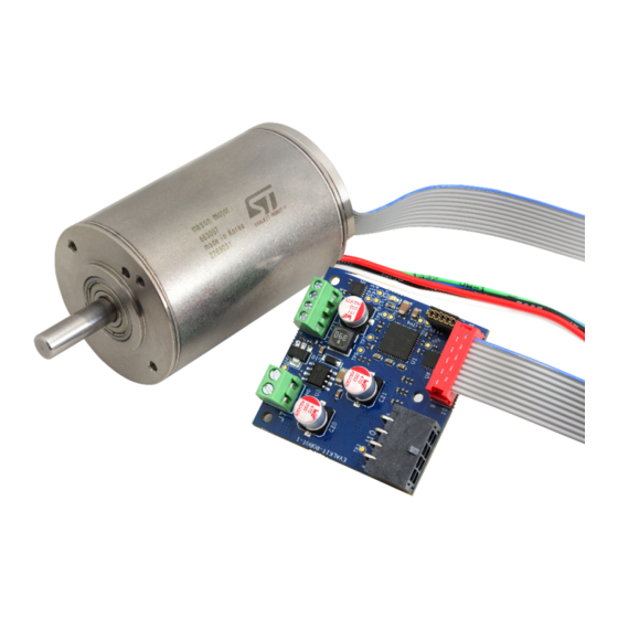
The STSW-ROBOT-1 firmware example for the EVALKIT-ROBOT-1 evaluation kit offers a ready-to-use brushless servomotor
solution consisting of the STSPIN32F0A control board and a maxon EC-i 40 brushless DC motor.
Figure 1.
EVALKIT-ROBOT-1
UM2711 - Rev 1 - April 2020
www.st.com
For further information contact your local STMicroelectronics sales office.
Advertisement
Table of Contents

Related Manuals for ST UM2711


Summary of Contents for ST UM2711
-
Page 1: Figure 1. Evalkit-Robot-1
The STSW-ROBOT-1 firmware example for the EVALKIT-ROBOT-1 evaluation kit offers a ready-to-use brushless servomotor solution consisting of the STSPIN32F0A control board and a maxon EC-i 40 brushless DC motor. Figure 1. EVALKIT-ROBOT-1 UM2711 - Rev 1 - April 2020 www.st.com For further information contact your local STMicroelectronics sales office. -
Page 2: Hardware And Software Requirements
An SWD programmer/debugger supporting the STM32F0 family, such as the STLINK-V3 from STMicroelectronics. 1. The operating range of the control electronics is between 12 V and 45 V. However, the system provides best performance with a supply voltage of 36 V ±20 % UM2711 - Rev 1 page 2/18... -
Page 3: Getting Started
Encoder alignment: Mechanical alignment procedure is executed Main loop: Infinite loop monitoring command request, execution and faults Motor control loop (interrupt based): executes the PMSM FOC algorithm (part of MCSDK) MODBUS loop (interrupt based): manages the MODBUS RTU communication UM2711 - Rev 1 page 3/18... -
Page 4: Mc_Api
Returns the target position in degrees stored in holding registers • getMovementDuration_s: Returns the target movement duration (seconds) according to the value in the holding registers (milliseconds) • getNewCommand: Returns true if MOVE coil is high • clearCommand: Forces MOVE coil low UM2711 - Rev 1 page 4/18... -
Page 5: Customization
The package contains the MotorControl Workbench project used for code generation. Using this project, it is possible to modify all the configurations related to the control algorithm and related peripherals. Note: The communication protocol included in the MCSDK does not support RS485 implemented in the EVALKIT- ROBOT-1 board. UM2711 - Rev 1 page 5/18... - Page 6 Some changes on the peripheral setup or a complete clean-up of the project is needed: use the “GENERATE” function and follow the steps below. Step 4. After the code generation is completed, click on “Run STM32CubeMX”. UM2711 - Rev 1 page 6/18...
-
Page 7: Figure 3. Uart Configuration Panel (Basic)
Configure one of the available timers as PWM no output for the MODBUS RTU timeout management (by default TIM14). It must be set in order to increment at a 50 μs rate (PSC = 2399 for 48 MHz clock). UM2711 - Rev 1 page 7/18... -
Page 8: Figure 5. Tim14 Configuration Panel
Enable interrupts for USART (priority 3) and timers (priority 2). From the code generation point of view, select sequence ordering, IRQ handler generation and HAL_Handler call for the timers. For the USART only, select sequence ordering and IRQ handler generation. UM2711 - Rev 1 page 8/18... -
Page 9: Figure 7. Nvic Configuration Panel
After the code generation is completed, click on “open project”. Step 9. Open the stm32f0xx_it.c file and modify the empty interrupt handlers. Step 10. Modify the IRQ_Handler of the MODBUS RTU Timeout timer as shown below: Figure 9. MODBUS RTU timeout IRQ handler UM2711 - Rev 1 page 9/18... -
Page 10: Figure 10. Modbus Scheduler Timer Irq Handler
Modify the IRQ_Handler of the MODBUS scheduler timer as shown below: Figure 10. MODBUS scheduler timer IRQ handler Step 12. Modify the IRQ_Handler of the UART interface as shown below: Figure 11. UART IRQ handler UM2711 - Rev 1 page 10/18... -
Page 11: Starting From Stm32Cubemx Project
NOT directly related to the motor control algorithm. Note: The configuration of the peripherals related to the motor control algorithm should be modified though the MotorControl Workbench only. UM2711 - Rev 1 page 11/18... -
Page 12: Figure 13. Stm32Cubemx Project File Pinout Configuration
Not motor control timers: – TIM14: MODBUS timeout counter – TIM16: MODBUS polling timer – TIM2: unused timer also connected to the digital Hall effect sensors of the motor (PA0, PA1, PA2) – TIM17: unused timer UM2711 - Rev 1 page 12/18... -
Page 13: Figure 14. Custom Exti0_1_Irqhandler Handler
You can find it between the /* USER CODE BEGIN 1 */ and USER CODE END 1 */ comments at the end of the file as shown below. Figure 14. Custom EXTI0_1_IRQHandler handler Step 5. Compile the project. UM2711 - Rev 1 page 13/18... -
Page 14: Revision History
UM2711 Revision history Table 2. Document revision history Date Version Changes 07-Apr-2020 Initial release. UM2711 - Rev 1 page 14/18... -
Page 15: Table Of Contents
Revision history ...............14 UM2711 - Rev 1... - Page 16 Custom EXTI0_1_IRQHandler handler ..........13 UM2711 - Rev 1...
- Page 17 Document revision history ............. 14 UM2711 - Rev 1...
- Page 18 ST’s terms and conditions of sale in place at the time of order acknowledgement. Purchasers are solely responsible for the choice, selection, and use of ST products and ST assumes no liability for application assistance or the design of Purchasers’...
Need help?
Do you have a question about the UM2711 and is the answer not in the manual?
Questions and answers