Sign In
Upload
Manuals
Brands
ST Manuals
Motherboard
UM0969
User Manuals: ST UM0969 Motherboard
Manuals and User Guides for ST UM0969 Motherboard. We have
1
ST UM0969 Motherboard manual available for free PDF download: User Manual
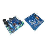
ST UM0969 User Manual (57 pages)
3-phase motor control demonstration board featuring IGBT intelligent power module STGIPS10K60A
Brand:
ST
| Category:
Motherboard
| Size: 3 MB
Table of Contents
Figure 1. STEVAL-IHM027V1 Demonstration Board
1
Table of Contents
2
1 System Introduction
6
Main Characteristics
6
Target Application
6
Safety and Operating Instructions
7
General Terms
7
Demonstration Board Intended Use
7
Demonstration Board Installation
7
Electrical Connections
8
2 Board Description
9
System Architecture
9
Figure 2. Motor Control System Architecture
9
Board Schematics
10
Figure 3. Input Stage with Bridge Schematic
10
Figure 4. Bus Voltage Sense Resistor Schematic
11
Figure 5. +5 V Linear Schematic
11
Figure 6. +3.3 V Linear Schematic
12
Figure 7. Buck Converter Schematic
12
Figure 8. Thermal Shutdown
13
Figure 9. NTC Bypass Schematic
14
Figure 10. Motor Output Schematic
14
Figure 11. +15 V Auxiliary Supply Schematic
15
Figure 12. Bemf_Daughter Board Schematic
15
Figure 13. Motor Control Connector Schematic
15
Figure 14. Hall Sensors\Encoder Schematic
16
Figure 15. Tachometer Sensor Schematic
16
Figure 16. Brake Control Schematic
17
Figure 17. STEVAL-IHM027V1 Schematic
18
Figure 18. Current Sensing a Schematic
18
Figure 19. Current Sensing B Schematic
19
Figure 20. Current Sensing C Schematic
19
Figure 21. Overcurrent\Overtemperature Protection Schematic
20
Circuit Description
21
Power Supply
21
Inrush Limitation
21
Brake Function
21
Figure 22. STEVAL-IHM027V1 Power Supply Block Diagram
21
Overcurrent Protection (OCP)
22
Current Sensing Amplifying Network
22
Figure 23. Three-Shunt Configuration
22
Table 1. Jumper Settings for a Single-Shunt or Three-Shunt Configuration
24
Figure 24. Single-Shunt Configuration
24
Tachometer and Hall/Encoder Input
25
Temperature Feedback and Overtemperature Protection (OTP)
25
Table 2. Internal IPM NTC Details (See Relevant Section on the STGIPS10K60A Datasheet)
26
Figure 25. OT Protection Circuit
26
3 Hardware Setting of the STEVAL-IHM027V1
27
Hardware Settings with Single-Shunt Configuration
27
Table 3. Jumper Settings for Single-Shunt Configuration
27
Hardware Settings with Three-Shunt Configuration
28
Table 4. Jumper Settings for Three-Shunt Configuration
28
Hardware Settings for Input Stage
29
Table 5. Input Stage Configuration Details
29
Figure 26. STEVAL-IHM027V1 Input Stage Detail
29
4 Description of Jumpers, Test Pins, and Connectors
30
Table 6. Jumpers Description
30
Table 7. Connector Pinout Description
32
Table 8. Testing Points Description
34
5 Connector Placement
35
Figure 27. Connector Placement
35
6 BOM List
36
Table 9. BOM List
36
7 PCB Layout
40
Figure 28. Copper Tracks - Top Side
40
Figure 29. Copper Tracks - Bottom Side
41
Figure 30. Silk Screen - Top Side
42
Figure 31. Silk Screen - Bottom Side
43
8 Power Losses and Dissipation
44
Assumptions
44
Conduction Loss
44
Figure 32. Static Parameter Calculations
45
Switching Loss
46
Thermal Impedance Overview
46
Table 10. RC - Cauer STGIPS10K60A Thermal Network
47
Figure 33. Equivalent STGIPS10K60A Thermal Network (CAUER Models)
47
Temperature Rise Considerations and Calculation Example
48
Figure 34. Maximum IC(RMS) Current Vs. Switching Frequency
48
9 Ordering Information
49
10 Using the STEVAL-IHM027V1 with STM32 FOC Firmware Library
50
11 Environmental Considerations
51
12 Hardware Requirements
52
13 Software Requirements
53
14 Conclusion
54
15 References
55
16 Revision History
56
Table 11. Document Revision History
56
Advertisement
Advertisement
Related Products
ST UM0804
ST UM0704
ST PractiSPIN UM0696
ST UM0920
ST UM0527
ST UM1461
ST UM1935
ST UM2163
ST UM2248
ST UM2414
ST Categories
Motherboard
Computer Hardware
Microcontrollers
Control Unit
Controller
More ST Manuals
Login
Sign In
OR
Sign in with Facebook
Sign in with Google
Upload manual
Upload from disk
Upload from URL