Table of Contents
Advertisement
Quick Links
Advertisement
Table of Contents

Related Manuals for Supermicro X12SPi-TF


Summary of Contents for Supermicro X12SPi-TF
- Page 1 X12SPi-TF USER'S MANUAL Revision 1.0b...
- Page 2 State of California, USA. The State of California, County of Santa Clara shall be the exclusive venue for the resolution of any such disputes. Supermicro's total liability for all claims will not exceed the price paid for the hardware product.
- Page 3 ECC RDIMM/LRDIMM memory with speeds of up to 3200MHz, SATA 3.0 ports, an M.2 slot, and a Trusted Platform Module (TPM) header. The X12SPi-TF is optimized for high- performance, high-end computing platforms that address the needs of next generation server applications.
- Page 4 Super X12SPi-TF User's Manual Contacting Supermicro Headquarters Address: Super Micro Computer, Inc. 980 Rock Ave. San Jose, CA 95131 U.S.A. Tel: +1 (408) 503-8000 Fax: +1 (408) 503-8008 Email: marketing@supermicro.com (General Information) support@supermicro.com (Technical Support) Website: www.supermicro.com Europe Address: Super Micro Computer B.V.
-
Page 5: Table Of Contents
Preface Table of Contents Chapter 1 Introduction 1.1 Checklist ..........................8 Quick Reference .......................11 Quick Reference Table ......................12 Motherboard Features .......................14 1.2 Processor and Chipset Overview ..................18 1.3 Special Features ........................18 Recovery from AC Power Loss ..................18 1.4 System Health Monitoring ....................19 Onboard Voltage Monitors ....................19 Fan Status Monitor with Firmware Control ...............19 Environmental Temperature Control .................19... - Page 6 Super X12SPi-TF User's Manual Tools Needed ........................30 Location of Mounting Holes ....................30 Installing the Motherboard....................31 2.4 Memory Support and Installation ..................32 Memory Support ........................32 General Guidelines for Optimizing Memory Performance ..........33 DIMM Installation ......................34 DIMM Removal .........................34 2.5 Rear I/O Ports ........................35 2.6 Front Control Panel ......................40...
- Page 7 Preface Chapter 4 UEFI BIOS 4.1 Introduction .........................69 4.2 Main Setup .........................70 4.3 Advanced ..........................72 4.4 Event Logs ........................107 4.5 IPMI ..........................109 4.6 Security ..........................112 4.7 Boot ..........................117 4.8 Save & Exit ........................119 Appendix A Software Installation A.1 Installing Software Programs ...................121 A.2 SuperDoctor 5 .........................122 ®...
-
Page 8: Chapter 1 Introduction
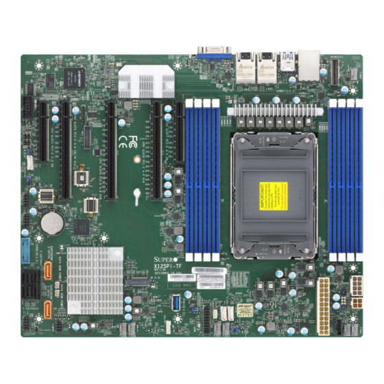
Introduction Congratulations on purchasing your computer motherboard from an industry leader. Supermicro motherboards are designed to provide you with the highest standards in quality and performance. In additon to the motherboard, several important parts that are included in the retail box are listed below. - Page 9 Chapter 1: Introduction Figure 1-1. X12SPi-TF Motherboard Image Note: All graphics shown in this manual were based upon the latest PCB revision available at the time of publication of the manual. The motherboard you received may or may not look exactly the same as the graphics shown in this manual.
- Page 10 Super X12SPi-TF User's Manual Figure 1-2. X12SPi-TF Motherboard Layout (not drawn to scale) USB4/5 (3.0) LEDBMC AST2600 X550 USB 0/1 LAN2 LAN1 IPMI_LAN COM1 MH15 MH16 JBT1 M.2-H MAC CODE BAR CODE X12SPi-TF JSD1 621A SAN MAC IPMI CODE REV: 2.00...
-
Page 11: Quick Reference
JIPMB1 JPME1 MH16 JI2C_FP1 USB2/3 JBT1 USB6/7 (3.2 Gen 1) JBT1 S-SATA0 I-SATA4~7 M.2-H MAC CODE BAR CODE JSD1 X12SPi-TF 621A JSD1 JPWR1 IPMI CODE SAN MAC REV: 2.00 JPWR1 JSD2 DESIGNED IN USA I-SATA0~3 JSD2 JPWR2 JPWR2 S-SATA1 BIOS LICENSE... -
Page 12: Quick Reference Table
Super X12SPi-TF User's Manual Quick Reference Table Jumper Description Default Setting JBT1 CMOS Clear Open (Normal) JPME1 ME Recovery Pins 1-2 (Normal) Description Status M.2 LED Blinking Green: Device Working LEDBMC BMC Heartbeat LED Blinking Green: BMC Normal LEDPWR Onboard Power LED... - Page 13 Chapter 1: Introduction Connector Description TPM1/PORT80 Trusted Platform Module/Port 80 Connector UID-SW Unit Identifier (UID) Switch USB0/1 Back Panel Universal Serial Bus (USB) 2.0 Ports USB2/3 Front Accessible USB 2.0 Headers USB4/5 Back Panel USB 3.2 Gen 1 Ports USB6/7 Front Accessible USB 3.2 Gen 1 Header USB8 USB 3.2 Gen 1 Type-A Header...
-
Page 14: Motherboard Features
Super X12SPi-TF User's Manual Motherboard Features Motherboard Features • Supports the 3rd generation Intel Xeon Scalable Processor series (Socket P+ (LGA4189)) processor with up to 40 cores and a thermal design power (TDP) of up to 270W Memory • Supports up to 2048GB of ECC RDIMM/LRDIMM/LRDIMM 3DS with speeds up to 3200MHz in eight slots. - Page 15 Chapter 1: Introduction Motherboard Features Peripheral Devices • Two USB 2.0 ports on the rear I/O panel (USB0/1) • Two USB 3.2 Gen 1 ports on the rear I/O panel (USB4/5) • One front accessible USB 2.0 headers with two USB connections (USB2/3) •...
- Page 16 Note 2: For IPMI configuration instructions, please refer to the Embedded IPMI Con- figuration User's Guide available at http://www.supermicro.com/support/manuals/. Note 3: If you purchase a Supermicro Out of Band (OOB) software license key (Supermicro P/N: SFT-OOB-LIC), please do not change the IPMI MAC address. Once you change the IPMI MAC address, the license will be invalid.
- Page 17 Chapter 1: Introduction Figure 1-3. System Block Diagram Note: This is a general block diagram and may not exactly represent the features on your motherboard. See the previous pages for the actual specifications of your moth- erboard.
-
Page 18: Processor And Chipset Overview
1.2 Processor and Chipset Overview Built upon the functionality and capability of the 3rd generation Intel Xeon Scalable Processor series (Socket P+ (LGA4189)) processor and the Intel PCH C621A chipset, the X12SPi-TF motherboard provides system performance, power efficiency, and feature sets to address the needs of next-generation computer users. -
Page 19: System Health Monitoring
Plug and Play, and an operating system-independent interface for configuration control. ACPI leverages the Plug and Play BIOS data structures, while providing a processor architecture-independent implementation that is compatible with appropriate Windows operating systems. For detailed information regarding OS support, please refer to the Supermicro website. -
Page 20: Power Supply
It is even more important for processors that have high CPU clock rates where noisy power transmission is present. The X12SPi-TF motherboard accommodates a 24-pin ATX power supply. Although most power supplies generally meet the specifications required by the CPU, some are inadequate. -
Page 21: Chapter 2 Installation
Chapter 2: Installation Chapter 2 Installation 2.1 Static-Sensitive Devices Electrostatic Discharge (ESD) can damage electronic com ponents. To avoid damaging your system board, it is important to handle it very carefully. The following measures are generally sufficient to protect your equipment from ESD. Precautions •... -
Page 22: Processor And Heatsink Installation
• Thermal grease is pre-applied on new heatsinks. No additional thermal grease is needed. • Refer to the Supermicro website for updates on processor support. • All graphics in this manual are for illustration purposes only. Your components may look different. -
Page 23: Overview Of The Processor Carrier Assembly
Chapter 2: Installation Overview of the Processor Carrier Assembly The processor carrier assembly contains the 3rd generation Intel Xeon Scalable Processor and a processor carrier. 1. Processor 2. Processor Carrier Overview of the CPU Socket The CPU socket is protected by a plastic protective cover. 1. -
Page 24: Overview Of The Processor Heatsink Module
Super X12SPi-TF User's Manual Overview of the Processor Heatsink Module The Processor Heatsink Module (PHM) contains a heatsink, a processor carrier, and the. 1. Heatsink with Thermal Grease 2. Processor Carrier 3. Processor Processor Heatsink Module... -
Page 25: Creating The Carrier Assembly
CPU Processor Carrier Assembly Pin 1 Note: The following CPU carriers have been successfully tested in our labs and are available from Supermicro. Please order the CPU carriers with the CPU heatsink. SKT-1205L-P4IC-FXC Intel 3rd Generation Xeon Scalable Processors... -
Page 26: Assembling The Processor Heatsink Module
Super X12SPi-TF User's Manual Assembling the Processor Processor Carrier Assembly (Upside Down) Heatsink Module After creating the processor carrier assembly for the processor, mount it onto the heatsink to create the processor heatsink module (PHM): 1. Note the label on top of the heatsink, which marks the heatsink mounting holes as 1, 2, 3, and 4. -
Page 27: Preparing The Cpu Socket For Installation
Chapter 2: Installation Preparing the CPU Socket for Installation This motherboard comes with a plastic protective cover installed on the CPU socket. Remove it from the socket to install the Processor Heatsink Module (PHM). Gently pull up one corner of the plastic protective cover to remove it. CPU Socket with Plastic Protective Cover Remove the plastic protective cover from the CPU socket. -
Page 28: Installing The Processor Heatsink Module
Super X12SPi-TF User's Manual Installing the Processor Heatsink Module After assembling the Processor Heatsink Module (PHM), install it onto the CPU socket: 1. Align hole 1 of the heatsink with the printed triangle on the CPU socket. See the left image below. -
Page 29: Removing The Processor Heatsink Module
Chapter 2: Installation Removing the Processor Heatsink Module Before removing the processor heatsink module (PHM) from the motherboard, shut down the Remove the screws in the sequence of 4, 3, 2, 1 system and then unplug the AC power cord from all power supplies. -
Page 30: Motherboard Installation
Super X12SPi-TF User's Manual 2.3 Motherboard Installation All motherboards have standard mounting holes to fit different types of chassis. Make sure that the locations of all the mounting holes for both the motherboard and the chassis match. Although a chassis may have both plastic and metal mounting fasteners, metal ones are highly recommended because they ground the motherboard to the chassis. -
Page 31: Installing The Motherboard
Chapter 2: Installation Installing the Motherboard 1. Install the I/O shield into the back of the chassis, if applicable. 2. Locate the mounting holes on the motherboard. See the previous page for the location. 3. Locate the matching mounting holes on the chassis. Align the mounting holes on the motherboard against the mounting holes on the chassis. -
Page 32: Memory Support And Installation
Important: Exercise extreme care when installing or removing DIMM modules to pre- vent any possible damage. Memory Support The X12SPi-TF supports up to 2048GB of ECC RDIMM/LRDIMM/LRDIMM 3DS with speeds up to 3200MHz in eight slots. Refer to the tables below for the recommended DIMM population order and additional memory information. -
Page 33: General Guidelines For Optimizing Memory Performance
AST2600 X550 USB 0/1 LAN2 LAN1 IPMI_LAN COM1 MH15 MH16 JBT1 M.2-H BAR CODE MAC CODE 621A X12SPi-TF JSD1 IPMI CODE SAN MAC REV: 2.00 JPWR1 DESIGNED IN USA JSD2 JPWR2 BIOS LICENSE JRK1 FANB FANA FAN4 FAN3 DIMMG1 DIMMB1... -
Page 34: Dimm Installation
Super X12SPi-TF User's Manual DIMM Installation 1. Insert the desired number of DIMMs USB4/5 (3.0) LEDBMC AST2600 X550 USB 0/1 LAN2 LAN1 IPMI_LAN COM1 into the memory slots based on the recommended DIMM population table on page 32. MH15 MH16 2. -
Page 35: Rear I/O Ports
X550 USB 0/1 LAN2 LAN1 IPMI_LAN COM1 MH15 MH16 JBT1 M.2-H BAR CODE MAC CODE 621A X12SPi-TF JSD1 SAN MAC IPMI CODE REV: 2.00 JPWR1 DESIGNED IN USA JSD2 JPWR2 BIOS LICENSE JRK1 FANB FANA FAN4 FAN3 Figure 2-1. I/O Port Locations and Definitions... - Page 36 Super X12SPi-TF User's Manual VGA Port A video (VGA) port is located next to LAN2 on the I/O back panel. Refer to the board layout below for the location. COM Ports There is one COM connection on this motherboard. COM1 is located next to PCIe slot 1.
- Page 37 X550 USB 0/1 LAN2 LAN1 IPMI_LAN COM1 3. IPMI LAN MH15 MH16 JBT1 M.2-H MAC CODE BAR CODE X12SPi-TF JSD1 621A IPMI CODE SAN MAC REV: 2.00 JPWR1 DESIGNED IN USA JSD2 JPWR2 BIOS LICENSE JRK1 FANB FANA FAN4 FAN3...
- Page 38 Super X12SPi-TF User's Manual Universal Serial Bus (USB) Ports There are two USB 2.0 ports (USB0/1) and two USB 3.2 Gen 1 ports (USB6/7) located on the I/O back panel. The motherboard also has two front access USB 2.0 headers (USB2/3 and USB4/5) and one front access USB 3.2 Gen 1 header (USB8/9).
- Page 39 USB4/5 (3.0) LEDBMC AST2600 X550 USB 0/1 LAN2 LAN1 IPMI_LAN COM1 MH15 MH16 JBT1 M.2-H MAC CODE BAR CODE X12SPi-TF JSD1 621A IPMI CODE SAN MAC REV: 2.00 JPWR1 DESIGNED IN USA JSD2 JPWR2 BIOS LICENSE JRK1 FANB FANA FAN4 FAN3...
-
Page 40: Front Control Panel
JF1 contains header pins for various buttons and indicators that are normally located on a control panel at the front of the chassis. These connectors are designed specifically for use with Supermicro chassis. See the figure below for the descriptions of the front control panel buttons and LED indicators. - Page 41 Chapter 2: Installation Power Button The Power Button connection is located on pins 1 and 2 of JF1. Momentarily contacting both pins will power on/off the system. This button can also be configured to function as a suspend button (with a setting in the BIOS - see Chapter 4). To turn off the power when the system is in suspend mode, press the button for 4 seconds or longer.
- Page 42 Super X12SPi-TF User's Manual Power Fail LED The Power Fail LED connection is located on pins 5 and 6 of JF1. Refer to the table below for pin definitions. Power Fail LED Pin Definitions (JF1) Pin# Definition 3.3V PWR Supply Fail...
- Page 43 Chapter 2: Installation NIC1/NIC2 (LAN1/LAN2) The NIC (Network Interface Controller) LED connection for LAN port 1 is located on pins 11 and 12 of JF1, and LAN port 2 is on pins 9 and 10. Attach the NIC LED cables here to display network activity.
- Page 44 Super X12SPi-TF User's Manual Power LED The Power LED connection is located on pins 15 and 16 of JF1. Refer to the table below for pin definitions. Power LED Pin Definitions (JF1) Pins Definition 3.3V Stby PWR LED NMI Button The non-maskable interrupt (NMI) button header is located on pins 19 and 20 of JF1.
-
Page 45: Connectors
USB4/5 (3.0) LEDBMC AST2600 X550 LAN2 LAN1 USB 0/1 IPMI_LAN COM1 MH15 MH16 JBT1 M.2-H MAC CODE BAR CODE X12SPi-TF JSD1 621A SAN MAC IPMI CODE REV: 2.00 JPWR1 DESIGNED IN USA JSD2 JPWR2 BIOS LICENSE JRK1 FANB FANA FAN4 FAN3... - Page 46 Super X12SPi-TF User's Manual 8-Pin Power Connector JPWR1 is an 8-pin 12V DC power input for the CPU that must be connected to the power supply. Refer to the table below for pin definitions. 8-pin Power Pin Definitions Pin# Definition...
-
Page 47: Headers
3. FAN1 4. FAN2 5. FAN3 MH15 6. FAN4 MH16 7. FAN5 JBT1 M.2-H BAR CODE MAC CODE 621A X12SPi-TF JSD1 SAN MAC IPMI CODE REV: 2.00 JPWR1 DESIGNED IN USA JSD2 JPWR2 BIOS LICENSE JRK1 FANB FANA FAN4 FAN3... - Page 48 Super X12SPi-TF User's Manual SGPIO Headers There is one Serial Link General Purpose Input/Output (S-SGPIO1) header located on the motherboard. S-SGPIO is for sSATA use. Refer to the tables below for pin definitions. SGPIO Header Pin Definitions Pin# Definition Pin#...
- Page 49 Port 80 connection. Use this header to enhance system performance and data security. Refer to the table below for pin definitions. Please go to the following link for more information on the TPM: http://www.supermicro.com/manuals/other/TPM.pdf. Trusted Platform Module Header Pin Definitions...
- Page 50 Super X12SPi-TF User's Manual Power SMB (I C) Header The Power System Management Bus (I C) connector (JPI C1) monitors the power supply, fan, and system temperatures. Refer to the table below for pin definitions. Power SMB Header Pin Definitions...
- Page 51 Definition Intrusion Input Ground NVMe I C Header Connector JNVI C1 is a management header for the Supermicro AOC NVMe PCIe peripheral cards. Please connect the I C cable to this connector. 1. Chassis Intrusion USB4/5 (3.0) LEDBMC 2. NVMe I...
- Page 52 Baseboard Management Controller (BMC) and a Network Interface Controller (NIC). For the network sideband interface to work properly, you will need to use a NIC add-on card that supports NC-SI and also need to have a special cable. Please contact Supermicro at www. supermicro.com to purchase the cable for this header.
- Page 53 5. I-SATA4 MH15 6. I-SATA5 MH16 7. I-SATA6 8. I-SATA7 9. S-SATA0 JBT1 10. S-SATA1 M.2-H BAR CODE MAC CODE X12SPi-TF JSD1 621A SAN MAC IPMI CODE REV: 2.00 JPWR1 DESIGNED IN USA 11. M.2 Slot JSD2 JPWR2 BIOS LICENSE...
- Page 54 Super X12SPi-TF User's Manual SMB (I C) for LCD Connector The connector used for System Management Bus (I C) for LCD devices is located at JI2C_ FP1. Connect a cable here to provide health monitoring and management for LCD devices.
- Page 55 USB4/5 (3.0) LEDBMC AST2600 X550 USB 0/1 LAN2 LAN1 IPMI_LAN COM1 MH15 MH16 JBT1 M.2-H MAC CODE BAR CODE X12SPi-TF JSD1 621A SAN MAC IPMI CODE REV: 2.00 JPWR1 DESIGNED IN USA JSD2 JPWR2 BIOS LICENSE JRK1 FANB FANA FAN4 FAN3...
-
Page 56: Jumper Settings
Super X12SPi-TF User's Manual 2.8 Jumper Settings How Jumpers Work To modify the operation of the motherboard, jumpers can be used to choose between optional settings. Jumpers create shorts between two pins to change the function of the connector. Pin 1 is identified with a square solder pad on the printed circuit board. See the diagram below for an example of jumping pins 1 and 2. - Page 57 USB4/5 (3.0) LEDBMC AST2600 X550 USB 0/1 LAN2 LAN1 IPMI_LAN COM1 MH15 MH16 JBT1 M.2-H MAC CODE BAR CODE X12SPi-TF JSD1 621A SAN MAC IPMI CODE REV: 2.00 JPWR1 DESIGNED IN USA JSD2 JPWR2 BIOS LICENSE JRK1 FANB FANA FAN4 FAN3...
-
Page 58: Led Indicators
Super X12SPi-TF User's Manual 2.9 LED Indicators LAN LEDs Two LAN ports (LAN1 and LAN2) are located on the I/O back panel of the motherboard. Each Ethernet LAN port has two LEDs. The green LED indicates activity, while the other Link LED may be green, amber, or off to indicate the speed of the connection. - Page 59 2. M.2 LED AST2600 X550 USB 0/1 LAN2 LAN1 IPMI_LAN COM1 MH15 MH16 JBT1 M.2-H MAC CODE BAR CODE 621A X12SPi-TF JSD1 IPMI CODE SAN MAC REV: 2.00 JPWR1 DESIGNED IN USA JSD2 JPWR2 BIOS LICENSE JRK1 FANB FANA FAN4 FAN3...
- Page 60 Super X12SPi-TF User's Manual Onboard Power LED The Onboard Power LED is located at LEDPWR on the motherboard. When this LED is on, the system is on. Turn off the system and unplug the power cord before removing or installing components.
-
Page 61: Chapter 3 Troubleshooting
Chapter 3: Troubleshooting Chapter 3 Troubleshooting 3.1 Troubleshooting Procedures Use the following procedures to troubleshoot your system. If you have followed all of the procedures below and still need assistance, refer to the ‘Technical Support Procedures’ and/ or ‘Returning Merchandise for Service’ section(s) in this chapter. Always disconnect the AC power cord before adding, changing or installing any non hot-swap hardware components. -
Page 62: System Boot Failure
Super X12SPi-TF User's Manual System Boot Failure If the system does not display POST (Power-On-Self-Test) or does not respond after the power is turned on, do the following: 1. Check the screen for an error message. 2. Clear the CMOS settings by unplugging the power cord and contacting both pads on the CMOS clear jumper (JBT1). -
Page 63: When The System Becomes Unstable
Chapter 3: Troubleshooting When the System Becomes Unstable A. If the system becomes unstable during or after OS installation, check the following: 1. CPU/BIOS support: Make sure that your CPU is supported and that you have the latest BIOS installed in your system. 2. - Page 64 Super X12SPi-TF User's Manual 6. To find out if a component is good, swap this component with a new one to see if the system will work properly. If so, then the old component is bad. You can also install the component in question in another system.
-
Page 65: Technical Support Procedures
Before contacting Technical Support, please take the following steps. Also, please note that as a motherboard manufacturer, Supermicro also sells motherboards through its channels, so it is best to first check with your distributor or reseller for troubleshooting services. They should know of any possible problems with the specific system configuration that was sold to you. -
Page 66: Frequently Asked Questions
Updated BIOS files are located on our website at http:// www.supermicro.com/ResourceApps/BIOS_IPMI_Intel.html. Please check our BIOS warning message and the information on how to update your BIOS on our website. Select your motherboard model and download the BIOS file to your computer. Also, check the current BIOS revision to make sure that it is newer than your BIOS before downloading. -
Page 67: Battery Removal And Installation
Chapter 3: Troubleshooting 3.4 Battery Removal and Installation Battery Removal To remove the onboard battery, follow the steps below: 1. Power off your system and unplug your power cable. 2. Locate the onboard battery as shown below. 3. Using a tool such as a pen or a small screwdriver, push the battery lock outwards to unlock it. -
Page 68: Returning Merchandise For Service
Super X12SPi-TF User's Manual 3.5 Returning Merchandise for Service A receipt or copy of your invoice marked with the date of purchase is required before any warranty service will be rendered. You can obtain service by calling your vendor for a Returned Merchandise Authorization (RMA) number. -
Page 69: Chapter 4 Uefi Bios
Chapter 4: BIOS Chapter 4 UEFI BIOS 4.1 Introduction This chapter describes the AMIBIOS™ Setup utility for the motherboard. The BIOS is stored on a chip and can be easily upgraded using a flash program. Note: Due to periodic changes to the BIOS, some settings may have been added or deleted and might not yet be recorded in this manual. -
Page 70: Main Setup
Super X12SPi-TF User's Manual 4.2 Main Setup When you first enter the AMI BIOS setup utility, you will enter the Main setup screen. You can always return to the Main setup screen by selecting the Main tab on the top of the screen. - Page 71 Chapter 4: BIOS CPLD Version This feature displays the Complex Programmable Logic Device version. Memory Information Total Memory This feature displays the total size of memory available in the system.
-
Page 72: Advanced
Super X12SPi-TF User's Manual 4.3 Advanced Use the arrow keys to select the Advanced menu and press <Enter> to access the menu features. Warning: Take caution when changing the Advanced settings. An incorrect value, a very high DRAM frequency, or an incorrect DRAM timing setting may make the system unstable. When this occurs, revert to default manufacturer settings. - Page 73 Chapter 4: BIOS Wait For "F1" If Error Use this feature to force the system to wait until the F1 key is pressed if an error occurs. The options are Disabled and Enabled. INT19 (Interrupt 19) Trap Response Interrupt 19 is the software interrupt that handles the boot disk function. When this feature is set to Immediate, the ROM BIOS of the host adapters will "capture"...
- Page 74 Super X12SPi-TF User's Manual Power Button Function This feature controls how the system shuts down when the power button is pressed. Select 4 Seconds Override for you to power off the system after pressing and holding the power button for four seconds or longer. Select Instant Off to instantly power off the system as soon as you press the power button.
- Page 75 Chapter 4: BIOS Hardware Prefetcher If set to Enable, the hardware prefetcher will prefetch streams of data and instructions from the main memory to the L2 cache to improve CPU performance. The options are Enable and Disable. Adjacent Cache Prefetch The CPU prefetches the cache line for 64 bytes if this feature is set to Disabled.
- Page 76 Super X12SPi-TF User's Manual AES-NI Select Enable to use the Intel Advanced Encryption Standard (AES) New Instructions (NI) to ensure data security. The options are Disable and Enable. TME, TME-MT, TDX Total Memory Encryption (TME) Use this feature to enable or disable total memory encryption. The options are Disabled and Enabled.
- Page 77 Chapter 4: BIOS CPU P State Control SpeedStep (Pstates) Intel SpeedStep Technology allows the system to automatically adjust processor voltage and core frequency to reduce power consumption and heat dissipation. The options are Disable and Enable. Dynamic SST-PP Use this feature to enable or disable Intel Speed Select Technology Performance Profile (SST-PP).
- Page 78 Super X12SPi-TF User's Manual CPU Flex Ratio Override Use this feature to enable or disable CPU Flex Ratio Prgoramming. The options are Disable and Enable. If the feature above is set to Enable, the next feature is available for configuration: CPU Core Flex Ratio Use this feature to set the non-turbo mode processor core ratio multiplier.
- Page 79 Chapter 4: BIOS Package C State Control Package C State This feature allows you to set the limit on the C State package register. The options are C0/C1 state, C2 state, C6(non Retention) state, and Auto. CPU T State Control Software Controlled T-States Use this feature to enable Software Controlled T-States.
- Page 80 Super X12SPi-TF User's Manual Degrade Precedence Use this feature to set degrade precedence when system settings are in conflict. Select Topology Precedence to degrade Features. Select Feature Precedence to degrade Topol- ogy. The options are Topology Precedence and Feature Precedence.
- Page 81 Chapter 4: BIOS Snoop Throttle Configuration Use this feature to select the level of snoop throttle setting. The options are Disabled, Low, Medium, High, and Auto. PCIe Remote P2P Relaxed Ordering Enable peer-to-peer relaxed ordering to optimize system performance. The options are Disable and Enable.
- Page 82 Super X12SPi-TF User's Manual Data Scrambling for DDR4 Use this feature to enable or disable data scrambling for DDR4 memory. The options are Disable and Enable. 2x Refresh Enable Use this feature to enable 2x memory refresh support to enhance memory performance.
- Page 83 Chapter 4: BIOS Patrol Scrub Patrol Scrubbing is a process that allows the CPU to correct correctable memory errors detected on a memory module and send the correction to the requestor (the original source). When this feature is set to Enable, the IO hub reads and writes back one cache line every 16K cycles if there is no delay caused by internal processing.
- Page 84 Super X12SPi-TF User's Manual IOAT Configuration Disable TPH Transparent Huge Pages (TPH) is a Linux memory management system that enables communication in larger blocks (pages). Enabling this feature increases performance. The options are No and Yes. *If the feature above is set to No, the feature below is available for configura-...
- Page 85 Chapter 4: BIOS Intel(R) VMD Technology Intel(R) VMD Technology Intel® VMD Technology NVMe Mode Switch Use this feature to select the NVMe mode. The options are Manual, VMD, and Auto. *If the feature above is set to Manual, the following features are available for configuration: Intel(R) VMD Technology ...
- Page 86 Super X12SPi-TF User's Manual Hot Plug Capable Use this feature to enable or disable hot plug for this port. The options are Dis- able and Enable. VMD Config for IOU 1 Enable/Disable VMD Use this feature to enable or disable the volume management device for this stack.
- Page 87 Chapter 4: BIOS VMD Config for IOU 4 Enable/Disable VMD Use this feature to enable or disable the volume management device for this stack. The options are Disable and Enable. If the feature above is set to Enable, the following features are available for configuration: CPU SLOT7 PCI-E 4.0 X8 Use this feature to enable or disable volume management device for this port.
- Page 88 Super X12SPi-TF User's Manual South Bridge The following USB information is displayed: • USB Module Version • USB Devices Legacy USB Support This feature enables support for USB 2.0 and older. The options are Enabled, Disabled, and Auto. XHCI Hand-off When this feature is disabled, the motherboard will not support USB 3.0.
- Page 89 Chapter 4: BIOS PCH SATA Configuration SATA Controller This feature enables or disables the onboard SATA controller supported by the Intel PCH chip. The options are Disable and Enable. Configure SATA as Select AHCI to configure an sSATA drive specified as an AHCI drive. Select RAID to configure an sSATA drive specified as a RAID drive.
- Page 90 Super X12SPi-TF User's Manual SATA Port 0-7 SATA Device Type Use this feature to specify if the SATA port specified should be connected to a Solid State Drive or a Hard Disk Drive. The options are Hard Disk Drive and Solid State Drive.
- Page 91 Chapter 4: BIOS sSATA Port 0/1/2 SATA Device Type Use this feature to specify if the SATA port specified should be connected to a Solid State Drive or a Hard Disk Drive. The options are Hard Disk Drive and Solid State Drive. Network Configuration ...
- Page 92 Super X12SPi-TF User's Manual Gateway addresses DNS addresses Interface ID Use this feature to set the 64-bit alternative interface ID for the device. DAD Transmit Count If this set feature is set to 0, the Duplication Address Detection is not performed. Set the value to a preferred selection.
- Page 93 Chapter 4: BIOS TCG Nvme KMS Status Retry Time Use this feature to select the number of attempts of test connections to the Key Management Server. The options are 0 - 300 seconds and the default is 60. Client UserName Press Enter to create a client username.
- Page 94 Super X12SPi-TF User's Manual Bus Master Enable Use this feature to enable the Bus Master, which enables the Bus Master Attribute for DMA transaction. The options are Disabled and Enabled. MMIO High Base Use this feature to select the base memory size according to memory-address mapping for the IO hub.
- Page 95 Chapter 4: BIOS CPU SLOT2 PCI-E 4.0 X8(IN X16) OPROM Use this feature to select which firmware type to be loaded for the add-on card in this slot. The options are Disabled and Legacy (if the Boot Mode Select feature under the Boot tab is set to Legacy), Disabled and EFI (if the Boot Mode Select feature under the Boot tab is set to UEFI), and Disabled, Legacy, and EFI (if the Boot Mode Select feature under the Boot tab is set to Dual).
- Page 96 Super X12SPi-TF User's Manual Onboard LAN1 Option ROM Use this feature to select a desired firmware function to be loaded for onboard LAN1. The options are Disabled and Legacy (if the Boot Mode Select feature under the Boot tab is set...
- Page 97 Chapter 4: BIOS Device Settings This feature displays the status of a serial port. Change Settings This feature specifies the base I/O port address and the Interrupt Request address of the serial port. Select Auto to allow the BIOS to automatically assign the base I/O and IRQ address.
- Page 98 Super X12SPi-TF User's Manual Parity A parity bit can be sent along with regular data bits to detect data transmission errors. Select Even if the parity bit is set to 0, and the number of 1's in data bits is even. Select Odd if the parity bit is set to 0, and the number of 1's in data bits is odd.
- Page 99 Chapter 4: BIOS SOL Console Redirection Select Enabled to use the SOL port for Console Redirection. The options are Disabled and Enabled. *If the feature above is set to Enabled, the following features are available for configuration: SOL Console Redirection Settings Use this feature to specify how the host computer exchanges data with the client computer, which is the remote computer used by the user.
- Page 100 Super X12SPi-TF User's Manual Flow Control Use this feature to set the flow control for Console Redirection to prevent data loss caused by buffer overflow. Send a "Stop" signal to stop sending data when the receiving buffer is full. Send a "Start" signal to start sending data when the receiving buffer is empty. The options are None and Hardware RTS/CTS.
- Page 101 Chapter 4: BIOS *If the feature above is set to Enabled, the following features are available for configuration: EMS Console Redirection Settings This feature allows you to specify how the host computer exchanges data with the client computer, which is the remote computer used by the user. Out-of-Band Mgmt Port The feature selects a serial port in a client server to be used by the Microsoft Windows Emergency Management Services (EMS) to communicate with a remote host server.
- Page 102 Super X12SPi-TF User's Manual UMA-Based Clustering Use this feature to enable or disable Uniform Memory Access (UMA) clustering. The options are Disable (All2All) and Hemishpere (2-clusters). WHEA Support Select Enabled to support the Windows Hardware Error Architecture (WHEA) platform and...
- Page 103 Use this feature to disable or enable Platform Hierarchy (PH) Randomization. The options are Disabled and Enabled. SMCI BIOS-Based TPM Provision Support Use this feature to enable the Supermicro TPM Provision support. The options are Disabled and Enabled. TXT Support Use this feature to enable or disable TXT Support.
- Page 104 Super X12SPi-TF User's Manual Select IPv4 or IPv6 Use this feature to select which LAN port to boot from. The options are IPv4 and IPv6. Boot Description Highlight the feature and press enter to create a boot description. The description cannot be more than 75 characters.
- Page 105 Chapter 4: BIOS NIC Configuration Link Speed Use this feature to specify the port speed used for the selected boot protocol. The options are Auto Negotiated, 10 Mbps Half, 10 Mbps Full, 100 Mbps Half, and 100 Mbps Full. Wake On LAN Select Enabled for wake on LAN support, which allows the system to wake up when an onboard LAN device receives an incoming signal.
- Page 106 Super X12SPi-TF User's Manual Commit Changes and Exit Use this feature to save all changes and exit TLS settings. Discard Changes and Exit Use this feature to discard all changes and exit TLS settings. Delete Certification Use this feature to delete certification.
-
Page 107: Event Logs
Chapter 4: BIOS 4.4 Event Logs Use this menu to configure Event Log settings. Change SMBIOS Event Log Settings Enabling/Disabling Options SMBIOS Event Log Change this feature to enable or disable all features of the SMBIOS Event Logging during system boot. The options are Disabled and Enabled. Erasing Settings Erase Event Log If No is selected, data stored in the event log will not be erased. - Page 108 Super X12SPi-TF User's Manual SMBIOS Event Log Standard Settings Log System Boot Event This option toggles the System Boot Event logging to enabled or disabled. The options are Disabled and Enabled. MECI The Multiple Event Count Increment (MECI) counter counts the number of occurrences that a duplicate event must happen before the MECI counter is incremented.
-
Page 109: Ipmi
Chapter 4: BIOS 4.5 IPMI Use this menu to configure Intelligent Platform Management (IPMI) settings. BMC Firmware Revision This feature indicates the IPMI firmware revision used in your system. IPMI STATUS (Baseboard Management Controller) This feature indicates the status of the IPMI firmware installed in your system. System Event Log Enabling/Disabling Options SEL Components... - Page 110 Super X12SPi-TF User's Manual When SEL is Full This feature allows you to decide what the BIOS should do when the system event log is full. Select Erase Immediately to erase all events in the log when the system event log is full. The options are Do Nothing and Erase Immediately.
- Page 111 Chapter 4: BIOS Station MAC Address Gateway IP Address This feature displays the Gateway IP address for this computer. The address can be manually entered. This should be in decimal and in dotted quad form (i.e., 172.31.0.1). VLAN This feature displays the virtual LAN settings. The options are Disabled and Enabled. VLAN ID This feature is enabled if VLAN is enabled.
-
Page 112: Security
Super X12SPi-TF User's Manual 4.6 Security Use this menu to configure the following security settings for the system. Administrator Password Press Enter to create a new, or change an existing, Administrator password. Password Check Select Setup for the system to check for a password at Setup. Select Always for the system to check for a password at boot up or upon entering the BIOS Setup utility. - Page 113 Erase - PSID, and Security Erase - Wtihout Password. Password Use this feature to set a password for the Supermicro HDD Security Function. Lockdown Mode Use this feature to put the BIOS into lockdown mode. The options are Enabled and Disabled.
- Page 114 Super X12SPi-TF User's Manual Restore Factory Keys Force System to User Mode. Install factory default Secure Boot key databases. Reset to Setup Mode This feature deletes all Secure Boot key databases from NVRAM. Export Secure Boot variables This feature allows you to copy NVRAM content of Secure boot variables to files in a root folder on a file system device.
- Page 115 Chapter 4: BIOS Append Select Yes to add the KEK from the manufacturer's defaults list to the existing KEK. Select No to load the KEK from a file. Authorized Signatures Update Select Yes to load the DB from the manufacturer's defaults. Select No to load the DB from a file.
- Page 116 Super X12SPi-TF User's Manual Append Select Yes to add the DBR from the manufacturer's defaults list to the existing DBR. Select No to load the DBR from a file.
-
Page 117: Boot
Chapter 4: BIOS 4.7 Boot Use this menu to configure Boot settings. Boot Mode Select Use this feature to select the type of device that the system is going to boot from. The options are Legacy, UEFI, and Dual. Legacy to EFI Support Select Enabled to boot EFI OS support after Legacy boot order has failed. - Page 118 Super X12SPi-TF User's Manual • Boot Option #4 • Boot Option #5 • Boot Option #6 • Boot Option #7 • Boot Option #8 • Boot Option #9 Delete Boot Option This feature allows you to select a boot device to delete from the boot priority list.
-
Page 119: Save & Exit
Chapter 4: BIOS 4.8 Save & Exit Use this menu to save settings and exit from the BIOS. Save Options Discard Changes and Exit Select this option to quit the BIOS Setup without making any permanent changes to the system configuration, and reboot the computer. Select Discard Changes and Exit from the Save &... - Page 120 Super X12SPi-TF User's Manual Default Options Load Optimized Defaults To set this feature, select Restore Defaults from the Save & Exit menu and press <Enter>. These are factory settings designed for maximum system stability, but not for maximum performance. Save As User Defaults To set this feature, select Save as User Defaults from the Save &...
-
Page 121: Appendix A Software Installation
Appendix A Software Installation A.1 Installing Software Programs The Supermicro site that contains drivers and utilities for your system is at https://www. supermicro.com/wdl/driver/. Some of these must be installed, such as the chipset driver. After accessing the site, go into the CDR_Images directory and locate the ISO file for your motherboard. -
Page 122: Superdoctor ® 5
SATA settings back to your original settings. A.2 SuperDoctor ® The Supermicro SuperDoctor 5 is a hardware monitoring program that functions in a command-line or web-based interface in Windows and Linux operating systems. The program monitors system health information such as CPU temperature, system voltages, system power consumption, fan speed, and provides alerts via email or Simple Network Management Protocol (SNMP). -
Page 123: Ipmi
Appendix A: Software Installation A.3 IPMI The X12SPi-TF supports the Intelligent Platform Interface (IPMI). IPMI is used to provide remote access, monitoring and management. There are several BIOS settings that are related to IPMI. Supermicro ships standard products with a unique password for the BMC ADMIN user. This password can be found on a label on the motherboard. -
Page 124: Appendix B Standardized Warning Statements
The following statements are industry standard warnings, provided to warn the user of situations which have the potential for bodily injury. Should you have questions or experience difficulty, contact Supermicro's Technical Support department for assistance. Only certified technicians should attempt to install or configure components. - Page 125 Appendix B: Warning Statements Attention Danger d'explosion si la pile n'est pas remplacée correctement. Ne la remplacer que par une pile de type semblable ou équivalent, recommandée par le fabricant. Jeter les piles usagées conformément aux instructions du fabricant. ¡Advertencia! Existe peligro de explosión si la batería se reemplaza de manera incorrecta.
-
Page 126: Product Disposal
Super X12SPi-TF User's Manual Product Disposal Warning! Ultimate disposal of this product should be handled according to all national laws and regulations. 製品の廃棄 この製品を廃棄処分する場合、 国の関係する全ての法律 ・ 条例に従い処理する必要があります。 警告 本产品的废弃处理应根据所有国家的法律和规章进行。 警告 本產品的廢棄處理應根據所有國家的法律和規章進行。 Warnung Die Entsorgung dieses Produkts sollte gemäß allen Bestimmungen und Gesetzen des Landes erfolgen.
Need help?
Do you have a question about the X12SPi-TF and is the answer not in the manual?
Questions and answers