Table of Contents
Advertisement
Quick Links
HPE Apollo 4200 Gen10 System User Guide
Abstract
This document is for the person who installs, administers, and troubleshoots servers and storage systems. Hewlett Packard
Enterprise assumes that you are qualified in the servicing of computer equipment and trained in recognizing hazards in
products with hazardous energy levels.
Part Number: P08483-006
Published: September 2020
Edition: 6
Advertisement
Table of Contents

Subscribe to Our Youtube Channel
Related Manuals for Hewlett Packard Enterprise HPE Apollo 4200 Gen10


Summary of Contents for Hewlett Packard Enterprise HPE Apollo 4200 Gen10
- Page 1 HPE Apollo 4200 Gen10 System User Guide Abstract This document is for the person who installs, administers, and troubleshoots servers and storage systems. Hewlett Packard Enterprise assumes that you are qualified in the servicing of computer equipment and trained in recognizing hazards in products with hazardous energy levels.
- Page 2 Nothing herein should be construed as constituting an additional warranty. Hewlett Packard Enterprise shall not be liable for technical or editorial errors or omissions contained herein.
-
Page 3: Table Of Contents
Contents Component identification...................... 7 Front panel components........................................7 Rear panel components.......................................... 8 Rear panel LEDs............................................11 System board components........................................12 DIMM slot locations......................................13 DIMM label identification....................................14 HPE Persistent Memory module label identification........................16 System maintenance switch descriptions..............................16 NMI functionality........................................17 Front panel LEDs and buttons......................................18 UID button functionality....................................20 Front panel LED power fault codes................................20 Drive numbering............................................ - Page 4 Remove a rear drive cage........................................50 Setup............................53 HPE support services..........................................53 Set up the system............................................53 Operational requirements........................................56 Space and airflow requirements..................................56 Temperature requirements....................................57 Power requirements......................................57 Electrical grounding requirements................................58 System warnings and cautions......................................58 Rack warnings and cautions......................................59 Remove the shipping screws ......................................60 Installing hardware options.......................................61 Installing the system into the rack....................................
- Page 5 Installing an AC hot-plug power supply..............................109 HPE Smart Storage Battery......................................111 Installing the HPE Smart Storage Battery............................111 HPE Trusted Platform Module 2.0 Gen10 option............................113 Overview..........................................113 HPE Trusted Platform Module 2.0 guidelines...........................114 Installing and enabling the HPE TPM 2.0 Gen10 option......................114 Cabling..........................119 Cabling overview..........................................
- Page 6 Replace the system battery......................................150 Electrostatic discharge...................... 152 Specifications........................153 Environmental specifications......................................153 Mechanical specifications........................................153 Power supply specifications......................................154 Hot-plug power supply calculations..................................155 Websites..........................156 Support and other resources....................157 Accessing Hewlett Packard Enterprise Support..............................157 Accessing updates..........................................157 Remote support.............................................158 Warranty information.........................................158 Regulatory information........................................158 Documentation feedback.........................................159...
-
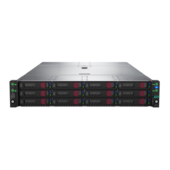
Page 7: Component Identification
Component identification Front panel components 12LFF dual cage configuration Item Description LFF hot-plug drives USB 2.0 port iLO Service Port 24SFF dual cage configuration Item Description SFF hot-plug drives USB 2.0 port iLO Service Port Component identification... -
Page 8: Rear Panel Components
Rear panel components Rear panel with the 4LFF hot-plug rear drive cage option Item Description PCIe3 x16 slot 7 for low-profile, standup expansion board PCIe3 x24 slot 6 for low-profile, standup expansion board PCIe3 x8 slot 5 for low-profile, standup expansion board Low-profile LFF hot-plug drives PCIe3 x24 slot 2 for low-profile, standup expansion board or riser cage options PCIe3 x16 slot 1 for low-profile, standup expansion board... - Page 9 Item Description PCIe3 x16 slot 7 for low-profile, standup expansion board PCIe3 x24 slot 6 for low-profile, standup expansion board PCIe3 x8 slot 5 for low-profile, standup expansion board SFF/uFF hot-plug drives PCIe3 x16 slot 3 for full-height riser cage PCIe3 x8 slot 4 for full-height riser cage PCIe3 x24 slot 2 for low-profile, standup expansion board or riser cage options PCIe3 x16 slot 1 for low-profile, standup expansion board...
- Page 10 Item Description Hot-plug power supply (bay 1) Power supply blank (bay 2) Video connector NIC port 2 NIC port 1 USB 3.0 ports iLO Management port 2 UID LED iLO Management port 1 The PCIe3 expansion slots 5-7 are associated with processor 2. The PCIe3 expansion slots 1-4 are associated with processor 1.
-
Page 11: Rear Panel Leds
The PCIe3 expansion slots 5-7 are associated with processor 2. The PCIe3 expansion slots 1-4 are associated with processor 1. Rear panel LEDs Item Description Status iLO port 1 link LED Green = Network link Off = No network link iLO port 1 activity LED Solid green = Link to network Flashing green = Network active... -
Page 12: System Board Components
Item Description Status NIC port 1 activity LED Solid green = Link to network Flashing green = Network active Off = No network activity NIC port 2 link LED Green = Network link Off = No network link NIC port 2 activity LED Solid green = Link to network Flashing green = Network active Off = No network activity... -
Page 13: Dimm Slot Locations
Item Description PCIe3 x16 slot 1 for low-profile, standup expansion board or riser cage options microSD card slot PCIe3 x24 slot 2 for low-profile, standup expansion board, riser cage option, or NVMe pass-through board TPM 2.0 connector Flexible Smart Array Controller slot PCIe3 x8 slot 5 for low-profile, standup expansion board System maintenance switch PCIe3 x24 slot 6 for low-profile, standup expansion board, riser cage options, or NVMe pass-through board... -
Page 14: Dimm Label Identification
The arrow points to the front of the system. DIMM label identification To determine DIMM characteristics, see the label attached to the DIMM. The information in this section helps you to use the label to locate specific information about the DIMM. Component identification... - Page 15 DIMM type R = RDIMM (registered) L = LRDIMM (load reduced) E = Unbuffered ECC (UDIMM) For more information about product features, specifications, options, configurations, and compatibility, see the product QuickSpecs on the Hewlett Packard Enterprise website (http://www.hpe.com/info/qs). Component identification...
-
Page 16: Hpe Persistent Memory Module Label Identification
256 GB 512 GB QR code Includes part number and serial number For more information about product features, specifications, options, configurations, and compatibility, see the product QuickSpecs on the Hewlett Packard Enterprise website (https://www.hpe.com/support/persistentmemoryQS). System maintenance switch descriptions Position Default Function Off = iLO 5 security is enabled. -
Page 17: Nmi Functionality
Before changing the boot mode to Legacy BIOS Mode, you must first disable the HPE Smart Array S100i Controller. NOTE: When you use the software to update, maintain, or monitor the HPE Apollo 4200 Gen10 system, you will see HPE ProLiant XL420 Gen10 Server as the product name in the interface. -
Page 18: Front Panel Leds And Buttons
To force the system to initiate the NMI handler and generate a crash dump log, do one of the following: • Use the iLO Virtual NMI feature. • Short the NMI header. For more information, see the Hewlett Packard Enterprise website (http://www.hpe.com/support/ilo-docs). Front panel LEDs and buttons Component identification... - Page 19 Item Description Status Power On/Standby button and • Solid green = System on system power LED • Flashing green (1 flash per second) = Performing power on sequence • Solid amber = System in standby • Off = No power present UID button/LED •...
-
Page 20: Uid Button Functionality
The UID button can be used to display the Server Health Summary when the system will not power on. For more information, see the latest HPE iLO 5 User Guide on the Hewlett Packard Enterprise website. Front panel LED power fault codes The following table provides a list of power fault codes, and the subsystems that are affected. - Page 21 48SFF hot-plug front drive numbering 4LFF hot-plug rear drive numbering 2SFF hot-plug rear drive numbering The drive numbering for the 2SFF rear drive cage varies depending on where it is connected. Item Drive numbering Internal drive cage 49, 51 HPE Smart Storage 49, 50 S100i SR Gen10 controller (RAID)
-
Page 22: Drive Leds
Item Drive numbering Internal drive cage 49, 50, 51, 52 HPE Smart Storage 49, 149, 50, 150 S100i SR Gen10 controller (RAID) HPE Smart Storage 1, 2, 3, 4 S100i SR Gen10 controller (HBA mode) Directly attached to 49, 149, 50, 150 controller 6SFF NVMe rear drive numbering 6SFF rear drive numbering (SAS, SATA) -
Page 23: Sff Drive Components And Leds
Item Status Definition Fault Solid amber The drive has failed. \Locate Solid blue The drive is operating normally and being identified by a management application. Flashing amber/blue The drive has failed, or a predictive failure alert has been received for this drive;... -
Page 24: Nvme Drive Components And Leds
Item Description Status Locate LED Solid blue = The drive is being identified by a host application. Flashing blue = The drive carrier firmware is being updated or requires an update. Activity ring LED Rotating green = Drive activity Off = No drive activity Drive status LED Solid green = The drive is a member of one or more logical drives. - Page 25 Item Description Release lever Activity ring Do Not Remove LED Request to Remove NVMe Drive button Do not remove an NVMe SSD from the drive bay while the Do Not Remove button LED is flashing. The Do Not Remove button LED flashes to indicate the device is still in use.
-
Page 26: Sff Flash Adapter Components And Led Definitions
Item Status Definition The drive is doing one of the following: Flashing green • Rebuilding • Performing a RAID migration • Performing a stripe size migration • Performing a capacity expansion • Performing a logical drive extension • Erasing Flashing amber/ The drive is a member of one or more logical drives and predicts the drive will fail. -
Page 27: Drive Cage Identification
Item Component Description Locate • Off—Normal • Solid blue—The drive is being identified by a host application. • Flashing blue—The drive firmware is being updated or requires an update. uFF drive ejection latch Removes the uFF drive when released. Do not remove LED •... -
Page 28: Drive Cage Backplane Identification
Item Description Rear drive cage (LFF, SFF, NVMe, or uFF) Internal drive cage Front drive cage Drive cage backplane identification 4LFF rear drive cage backplane Item Description x4 Mini SAS connector Power input connector 2SFF rear drive cage backplane Component identification... - Page 29 Item Description x4 Mini SAS connector Power input connector Six-bay SFF rear drive cage backplane (SAS, SATA) Item Description P2 connector P1 connector Power input connector Six-bay SFF NVMe rear drive cage backplane Component identification...
- Page 30 Item Description Fan connectors Power cable connector Backplane sideband cable connector NVMe port 1 connector NVMe port 2 connector NVMe port 3 connector Front and internal LFF drive cage backplane Item Front drive cage backplane Internal drive cage backplane P1 connector P1 connector P2 connector P2 connector...
-
Page 31: M.2 Ssd Slot Numbering
Item Front drive cage backplane Internal drive cage backplane P3 connector (reserved) P3 connector P1 connector P1 connector P2 connector P2 connector M.2 SSD slot numbering Item Description M.2 slot 1, port 1i M.2 slot 2, port 2i HPE Smart Array P824i-p MR Gen10 Controller Component identification... -
Page 32: Hpe Infiniband Hdr/Ethernet 940Qsfp 56X16 Adapter Leds
Components Item Description Internal SAS port 1i Internal SAS port 2i Internal SAS port 3i Internal SAS port 4i Controller backup power cable connector Internal SAS port 5i Internal SAS port 6i HPE InfiniBand HDR/Ethernet 940QSFP 56x16 adapter LEDs Link LED status Description A link has not been established. -
Page 33: Dsc-25 2-Port Sfp28 Card Ports And Leds
DSC-25 2-port SFP28 card ports and LEDs Ports Table 1: Ports Item Port Description Management port 1GbE RJ45 Network interface port 10/25G SFP+ based Network interface port 10/25G SFP+ based LEDs The HPE for Pensando DSP DSC-25 2p SFP28 card is a dual-port, single-slot, half-height, half-length (HHHL) SFP28 network adapter. -
Page 34: Hpe Ns204I-P Nvme Os Boot Device Components
Item Status Description SFP Port 1 Link/Activity A link has not been established Solid green Valid Ethernet link Flashing green Passing traffic; flashing frequency indicates traffic intensity Solid amber Link fault SFP Port 2 Link/Activity A link has not been established Solid green Valid Ethernet link Flashing green... -
Page 35: Hpe Ns204I-P Nvme Os Boot Device Led Definitions
Item Description Drive bay 1 Drive bay 2 Thermal interface pad with removable liner M.2 drive retaining latches HPE NS204i-p NVMe OS Boot Device LED definitions Item Description Fault LED status Bay 1 LED Off: Normal Flashing 1Hz: Drive predictive failure Bay 2 LED Amber: Drive failure Fan locations... - Page 36 NVMe rear drive cage fan numbering Component identification...
-
Page 37: Operations
Operations Power down the system IMPORTANT: When the system is in standby mode, auxiliary power is still being provided to the system. Before powering down the system for any upgrade or maintenance procedures, perform a backup of critical system data and programs. -
Page 38: Slide The Front Drive Cages Into The Chassis
Slide the front drive cages into the chassis After installation or maintenance, pull and hold the front drive cage rail release latches, and then slide the drive cages back into the chassis. Removing a drive WARNING: To reduce the risk of personal injury from hot surfaces, allow the drives, power supplies, and internal system components to cool before touching them. - Page 39 • If removing a drive from the front drive cage and the security bezel is installed, remove the bezel (Remove the bezel). • If removing a drive from the internal drive cage, extend the front and internal drive cages out of the chassis (Extend the front drive cages out of the chassis).
-
Page 40: Remove The System From The Rack
a. Determine the status of the drive from the NVMe LEDs (NVMe drive components and LEDs). b. Press the power button. The Do Not Remove button illuminates and flashes. c. When the Do Not Remove button stops flashing and the icon on the button is no longer illuminated, press the Do Not Remove button to release the release lever. - Page 41 WARNING: To reduce the risk of personal injury or damage to the equipment, be sure that: • The rack is bolted to the floor using the concrete anchor kit. • The leveling feet extend to the floor. • The full weight of the rack rests on the leveling feet. •...
-
Page 42: Remove The Access Panel
6. Place the system on a flat, level surface. Remove the access panel WARNING: To reduce the risk of personal injury from hot surfaces, allow the drives, power supplies, and internal system components to cool before touching them. Procedure 1. Power down the system (Power down the system). 2. -
Page 43: Install The Access Panel
Install the access panel Procedure 1. Place the access panel on top of the system, and then insert the tabs into the corresponding slots on the system. 2. Tighten the access panel screws. Open the cable management holder Procedure 1. Power down the system (Power down the system). 2. -
Page 44: Remove The Hpe Smart Storage Battery
a. Disconnect each power cord from the power source. b. Disconnect each power cord from the system. 3. Remove the system from the rack (Remove the system from the rack). 4. Place the system on a flat, level work surface. 5. -
Page 45: Remove The Air Baffle
8. Remove the cable from the air baffle clips, then remove the HPE Smart Storage Battery from the air baffle. Remove the air baffle Procedure 1. Power down the system (Power down the system). 2. Remove the system from the rack (Remove the system from the rack). 3. -
Page 46: Install The Air Baffle
6. Remove the HPE Smart Storage Battery if it is installed on the air baffle (Remove the HPE Smart Storage Battery). 7. Remove the air baffle. Install the air baffle Procedure 1. Insert the guide pins on the front edge of the air baffle into the holes located on the rear edge of the fan cage. 2. -
Page 47: Close The Cable Management Holder
Close the cable management holder Procedure 1. Secure all system cables in the cable management holder, and then connect them to the system board or controller board. 2. Return the cable management holder to its original position. 3. Install the air baffle (Install the air baffle ). Remove the rear drive cage blank Procedure 1. -
Page 48: Remove The Air Blocker From Pcie Expansion Slots 5-7
Remove the air blocker from PCIe expansion slots 5–7 The PCIe expansion slots 5–7 are associated with processor 2. To enable expansion board installation in these slots, remove the slot cover air blocker. Procedure 1. Power down the system (Power down the system). 2. -
Page 49: Remove The Pcie Riser Cage
Remove the PCIe riser cage WARNING: To reduce the risk of personal injury from hot surfaces, allow the drives and the internal system components to cool before touching them. CAUTION: To prevent damage to electrical components, take the appropriate anti-static precautions before beginning any installation, removal, or replacement procedure. -
Page 50: Remove A Rear Drive Cage
Remove a rear drive cage WARNING: To reduce the risk of personal injury from hot surfaces, allow the drives and the internal system components to cool before touching them. CAUTION: To prevent damage to electrical components, take the appropriate anti-static precautions before beginning any installation, removal, or replacement procedure. - Page 51 • Two-bay SFF hot-plug rear drive cage removal • Six-bay SFF NVMe drive cage removal Operations...
- Page 52 • Six-bay SFF rear drive cage (SAS or SATA) To replace the component, reverse the removal procedure. Operations...
-
Page 53: Setup
Startup and implementation services for both hardware and software • HPE Education Services – Help train your IT staff. For more information on HPE support services, see the Hewlett Packard Enterprise website. Set up the system Prerequisites Before setting up the system: •... - Page 54 ◦ Download it from the HPE support center website. ◦ Extract it from the SPP. Procedure Unbox the system 1. Unbox the system and verify the contents: • A server • A power cord • Rack-mounting hardware • Documentation 2. (Optional) Install hardware options. For installation instructions, see "Hardware options installation."...
- Page 55 For remote management, use the iLO virtual power button. Update the firmware 6. Using the SPP, update the following: • System ROM • Storage controller • Network adapters Set up storage 7. Do one of the following: • To configure the server to boot from a SAN, see the following guide: https://www.hpe.com/info/boot-from-san-config-guide •...
-
Page 56: Operational Requirements
Leave a minimum clearance of 121.9 cm (48 in) from the back of the rack to the back of another rack or row of racks. Hewlett Packard Enterprise systems draw in cool air through the front door and expel warm air through the rear door. -
Page 57: Temperature Requirements
The 9000 and 10000 Series Racks provide proper server cooling from flow-through perforations in the front and rear doors that provide 64 percent open area for ventilation. CAUTION: When using a Compaq branded 7000 series rack, install the high airflow rack door insert (PN 327281-B21 for 42U rack, PN 157847-B21 for 22U rack) to provide proper front-to-back airflow and cooling. -
Page 58: Electrical Grounding Requirements
Get help to lift and stabilize the product during installation or removal, especially when the product is not fastened to the rails. Hewlett Packard Enterprise recommends that a minimum of two people are required for all rack system installations. A third person may be required to help align the system if the system is installed higher than chest level. -
Page 59: Rack Warnings And Cautions
WARNING: To reduce the risk of fire or burns after removing the energy pack: • Do not disassemble, crush, or puncture the energy pack. • Do not short external contacts. • Do not dispose of the energy pack in fire or water. After power is disconnected, battery voltage might still be present for 1s to 160s. -
Page 60: Remove The Shipping Screws
Be sure sufficient clearance exists for cabling, installation and removal of the system, and movement of the rack doors. IMPORTANT: The HPE Apollo 4200 Gen10 System cable management arm is not supported on Compaq-branded 7000 series racks. Remove the shipping screws The system is secured with shipping hardware during the original product shipment. -
Page 61: Installing Hardware Options
Get help to lift and stabilize the product during installation or removal, especially when the product is not fastened to the rails. Hewlett Packard Enterprise recommends that a minimum of two people are required for all rack system installations. A third person may be required to help align the system if the system is installed higher than chest level. - Page 62 The following illustration shows the rack rail with the shelf portion highlighted in gray. Install the chassis retention brackets on the non-shelf portion of the rack rail. Install the system into the rack. Tighten the rack ear thumbscrews. Make sure the pins on the chassis retention brackets slot into the notches located on both sides of the chassis. Setup...
- Page 63 Install the drives in the front drive cages. Optional: Install the security bezel. Optional: Install the drives in the rear drive cage. WARNING: To reduce the risk of electric shock, fire, or damage to the equipment, do not plug telephone or telecommunications connectors into RJ-45 connectors.
-
Page 64: Power Up The System
If you do not need to modify the server configuration and are ready to install the system software, press the F10 key to access Intelligent Provisioning. For more information on automatic configuration, see the UEFI documentation on the Hewlett Packard Enterprise website. Setup... -
Page 65: Registering The Server
Registering the server To experience quicker service and more efficient support, register the product at the Hewlett Packard Enterprise Product Registration website. Setup... -
Page 66: Hardware Options Installation
Product QuickSpecs For more information about product features, specifications, options, configurations, and compatibility, see the product QuickSpecs on the Hewlett Packard Enterprise website (https://www.hpe.com/info/qs). Introduction Install any hardware options before initializing the system. For options installation information, see the option documentation. -
Page 67: Installing A Drive
• The system automatically sets all device numbers. If only one drive is used, install the drive in the drive bay with the lowest device number (Drive numbering). • • Drives must be the same capacity to provide the greatest storage space efficiency when drives are grouped together into the same drive array. - Page 68 • LFF drive • SFF drive • NVMe drive (rear drive cage only) • uFF drive (rear drive cage only) Hardware options installation...
-
Page 69: Drive Cage Options
CAUTION: Do not operate the system with any of the rear drive bays empty. To maintain proper airflow and sufficient cooling in the rear drive cage, all drive bays in this cage must have a drive or a drive blank. Hewlett Packard Enterprise recommends installing at least one drive in the rear drive cage before operating the system. -
Page 70: Installing The Two-Bay Sff Hot-Plug Rear Drive Cage And Two-Slot Pcie Riser Cage
If the system supports hot-plug components, minimize the amount of time the access panel is open. IMPORTANT: Hewlett Packard Enterprise recommends installing at least one drive in the rear drive cage. Populate drive bays based on the drive numbering sequence. Start from the drive bay with the lowest device number (Drive numbering). - Page 71 Installing the two-slot PCIe riser cage CAUTION: To prevent damage to electrical components, properly ground the system before beginning any installation procedure. Improper grounding can cause electrostatic discharge. Prerequisites Before you perform this procedure, make sure that you have the following items available: •...
- Page 72 Installing two-bay SFF hot-plug rear drive cage Prerequisites Before you perform this procedure, make sure that you have the following items available: • The components included with the hardware kit • Torx T-15 screwdriver Procedure Power down the system (Power down the system). Remove all power: a.
-
Page 73: Installing The Six-Bay Sff Nvme Rear Drive Cage
Installing the six-bay SFF NVMe rear drive cage IMPORTANT: Hewlett Packard Enterprise recommends installing at least one drive in the rear drive cage. Populate drive bays based on the drive numbering sequence. Start from the drive bay with the lowest device number (Drive numbering). - Page 74 If the preinstalled cables must be moved from one side of the drive cage to the other side, do the following: a. Loosen the screws from the plastic cover. b. Remove the plastic cover from the rear of the drive cage. c.
-
Page 75: Installing The Six-Bay Sff Rear Drive Cage (Sas, Sata)
Installing the six-bay SFF rear drive cage (SAS, SATA) IMPORTANT: Hewlett Packard Enterprise recommends installing at least one drive in the rear drive cage. Populate drive bays based on the drive numbering sequence. Start from the drive bay with the lowest device number (Drive numbering). -
Page 76: M.2 Ssd Enablement Board Option
For horizontal installation (two-slot PCI riser cage option required): PCIe3 x 8 riser board slot 3 and 4 For more information about product features, specifications, options, configurations, and compatibility, see the product QuickSpecs on the Hewlett Packard Enterprise website. Installing the M.2 SSD enablement board Procedure Power down the system (Power down the system). - Page 77 Remove the air baffle (Remove the air baffle). To install the M.2 SSD enablement board in the expansion slots 1 or 2, do the following: a. Remove the onboard PCIe expansion slot cover from the appropriate PCIe expansion slot. b. Install the M.2 SSD enablement board. Verify that the board is firmly seated in the slot. •...
- Page 78 c. Open the cable management holder (Open the cable management holder). d. Connect the SATA cables to the M.2 SSD enablement board and the system board. e. Secure the extra length of the SATA cables in the cable management holder. To install the M.2 SSD enablement board in the PCI riser cage, do the following: a.
-
Page 79: Expansion Slots
d. Install the PCIe riser cage (Installing the two-slot PCIe riser cage). Open the cable management holder (Open the cable management holder). 10. Secure the extra length of the SATA cables in the cable management holder. 11. Close the cable management holder (Close the cable management holder). 12. -
Page 80: Installing An Expansion Board Or Type -P Controller
Processor 2 (required) PCIe slot and card length Description Slot 5 - 1/2 length/Half-height (½L/HH) PCIe3 x8 (8, 4, 2, 1) Slot 6 - 1/2 length/Half-height (½L/HH) PCIe3 x24 (32, 16, 8, 4, 2, 1) Slot 7 - 1/2 length/Half-height (½L/HH) PCIe3 x16 (16, 8, 4, 2, 1) Installing an expansion board or type -p controller CAUTION: To prevent damage to electrical components, take the appropriate anti-static precautions before beginning... - Page 81 c. If installing an expansion board, verify that any switches or jumpers on the expansion board are set properly. For more information, see the documentation that ships with the option. d. Connect the cables to the expansion board or type -p controller (Cabling). e.
- Page 82 Item Description Type-p Smart Array controller connected to the controller backup power connector Energy pack connected to the energy pack connector Your server might appear different. f. Install the expansion board or controller. Verify that it is firmly seated in the slot. To install a full-height, half-length PCIe x16 expansion board, the two-slot PCIe riser cage option is required.
-
Page 83: Installing An Hpe Infiniband Hdr/Ethernet 200Gb 1-Port 940Qsfp56 X16 Adapter
f. Install the PCIe riser cage (Installing the two-slot PCIe riser cage). 10. Install any other options that connect to the expansion board or to the type -p controller. 11. Install the air baffle (Install the air baffle ). 12. Install the access panel (Install the access panel). 13. - Page 84 • Slots 3 and 6 • Slots 3 and 7 Procedure Power down the system (Power down the system). Remove all power: a. Disconnect each power cord from the power source. b. Disconnect each power cord from the system. Remove the system from the rack (Remove the system from the rack). Place the system on a flat, level work surface.
- Page 85 b. The white and black cables from the auxiliary card connect to the adapter board ports labeled WHITE CABLE and BLACK CABLE, respectively. The cable latch door must be open when connecting the cables. Close the cable latch door after connecting the cable. c.
- Page 86 d. Connect the other end of the black and white cables to the auxiliary card. Be sure that the cables on both cards are angled in the same direction after installation. CAUTION: Avoid routing the cables over any components in the system that may become hot such as the heatsink.
- Page 87 • Installing the adapter in slot 3 in the riser cage 10. Install the auxiliary card in the appropriate slot for processor 2 (PCIe slots 6 or 7). 11. Install the air baffle (Install the air baffle ). 12. Install the access panel (Install the access panel). Hardware options installation...
-
Page 88: Installing The Hpe Ns204I-P Nvme Os Boot Device Option
13. Install the system into the rack (Installing the system into the rack). 14. Power up the system (Power up the system). Installing the HPE NS204i-p NVMe OS Boot Device option Prerequisites Before beginning installation, ensure that the server is updated with the latest operating system firmware and drivers. Procedure Installing drives onto the boot device Remove the liner from the thermal interface pad. -
Page 89: Installing The Pensando Dsp Dsc-25 2P Sfp28 Card
a. Disconnect each power cord from the power source. b. Disconnect each power cord from the system. Remove the system from the rack (Remove the system from the rack). Place the system on a flat, level work surface. Remove the access panel (Remove the access panel). Select an available PCIe expansion slot that is x8 physical size and x4 electrical. - Page 90 a. Disconnect each power cord from the power source. b. Disconnect each power cord from the system. Remove the system from the rack (Remove the system from the rack). Place the system on a flat, level work surface. Remove the access panel (Remove the access panel). Remove the PCIe riser cage, if applicable.
-
Page 91: Controller Options
Type-p controllers—Type-p controllers install in a PCIe expansion slot. For more information on controllers, see the following documentation: • The controller family data sheet on the Hewlett Packard Enterprise website (https://www.hpe.com/h20195/V2/ Getdocument.aspx?docname=a00017196enw) • The controller QuickSpecs on the Hewlett Packard Enterprise website (http://www.hpe.com/info/qs) To configure the controller, see HPE Smart Storage Administrator. -
Page 92: Installing A Storage Controller
CAUTION: To prevent improper cooling and thermal damage, do not operate the server unless all PCI slots have either an expansion slot cover or an expansion board installed. CAUTION: Hewlett Packard Enterprise recommends performing a backup of all server data before installing or removing a controller or adapter. -
Page 93: Installing A Processor-Heatsink Assembly
For type-p Smart Array controllers, install the controller into an expansion slot (Installing an expansion board or • type -p controller). Connect all necessary cables to the controller depending on your system configuration (Cabling). Connect the controller backup power cable to the connector on the system or riser board. 10. - Page 94 IMPORTANT: Existing HPE ProLiant and HPE Synergy Gen10 server products containing first-generation Intel Xeon Scalable processors may not be upgraded to second-generation Intel Xeon Scalable processors at this time. For more information, see the product QuickSpecs on the Hewlett Packard Enterprise website (https://www.hpe.com/ info/qs).
-
Page 95: Memory Options
DIMMs can cause the server to halt during BIOS initialization. All memory installed in the system must be of the same type. DIMM population information For specific DIMM population information, see the DIMM population guidelines on the Hewlett Packard Enterprise website (https://www.hpe.com/docs/memory-population-rules). DIMM-processor compatibility The installed processor determines the type of DIMM that is supported in the system: •... -
Page 96: Hpe Smartmemory Speed Information
HPE SmartMemory speed information For more information about memory speed information, see the Hewlett Packard Enterprise website (https://www.hpe.com/ docs/memory-speed-table). DIMM label identification To determine DIMM characteristics, see the label attached to the DIMM. The information in this section helps you to use the label to locate specific information about the DIMM. -
Page 97: Installing A Dimm
R = RDIMM (registered) L = LRDIMM (load reduced) E = Unbuffered ECC (UDIMM) For more information about product features, specifications, options, configurations, and compatibility, see the HPE DDR4 SmartMemory QuickSpecs on the Hewlett Packard Enterprise website (https://www.hpe.com/support/ DDR4SmartMemoryQS). Installing a DIMM Procedure Power down the system (Power down the system). -
Page 98: Hpe Persistent Memory Option
Install the air baffle (Install the air baffle ). 10. Install the access panel (Install the access panel). 11. Install the system into the rack (Installing the system into the rack). 12. Power up the system (Power up the system). After installing the DIMMs, use BIOS/Platform Configuration (RBSU) in the UEFI System Utilities to configure the memory protection mode. - Page 99 Installing HPE Persistent Memory modules Use this procedure only for new HPE Persistent Memory module installations. If you are migrating this HPE Persistent Memory module from another system, see the HPE Persistent Memory User Guide on the Hewlett Packard Enterprise website (https:// www.hpe.com/info/persistentmemory-docs).
- Page 100 Prerequisites • Before beginning the installation, review the memory population guidelines on the Hewlett Packard Enterprise website (https://www.hpe.com/docs/memory-population-rules). • Before you perform this procedure, make sure that you have the following items available: ◦ The components included with the hardware option kit ◦...
-
Page 101: Internal Usb Device Option
HPE Persistent Memory, as well as evaluate and monitor the system memory configuration layout. For more information, see the HPE Persistent Memory User Guide on the Hewlett Packard Enterprise website (https:// www.hpe.com/info/persistentmemory-docs). Internal USB device option The server has one internal USB 3.0 port. -
Page 102: Power Supply Option
USB connector and is configured upon boot. To locate the internal and USB connector, see System board components. For more information, see the Dual 8Gb microSD EM USB storage device documentation on the Hewlett Packard Enterprise website (http://www.hpe.com/info/enterprise- docs). Power supply option WARNING: To reduce the risk of electric shock or damage to the equipment: •... - Page 103 WARNING: To reduce the risk of electric shock, fire, and damage to the equipment, you must install this product in accordance with the following guidelines: • This power supply is intended only for installation in Hewlett Packard Enterprise systems located in a restricted access location. •...
- Page 104 Crimp the ring tongue to the ground cable from the -48 V DC power source. Remove the terminal block connector. Hardware options installation...
- Page 105 Loosen the screws on the terminal block connector. Attach the ground (earthed) wire to the ground screw and washer and tighten to 1.47 N m (13 lb-in) of torque. The ground wire must be connected before the -48 V wire and the return wire. Hardware options installation...
- Page 106 Insert the -48 V wire into the left side of the terminal block connector, and then tighten the screw to 1.3 N m (10 lb-in) of torque. Insert the return wire into the right side of the connector, and then tighten the screw to 1.3 N m (10 lb-in) of torque. Hardware options installation...
- Page 107 Install the terminal block connector in the power supply. 10. To prevent accidental power cord disconnection when sliding the system in and out of the rack, secure the power cord, wires, and/or cables in the strain relief strap attached to the power supply handle: a.
- Page 108 11. Slide the power supply into the bay until it clicks into place. 12. Make sure the -48 V DC power source is off or the PDU breaker is in the off position, and then connect the power cord to the -48 V DC power source or PDU.
-
Page 109: Installing An Ac Hot-Plug Power Supply
WARNING: Remove power from the power supply before performing any installation steps or maintenance on the power supply. CAUTION: The server equipment connects the earthed conductor of the DC supply circuit to the earthing conductor at the equipment. For more information, see the documentation that ships with the power supply. CAUTION: If the DC connection exists between the earthed conductor of the DC supply circuit and the earthing conductor at the server equipment, the following conditions must be met: •... - Page 110 2. Slide the power supply into the bay until it clicks into place. 3. Connect the power cord to the power supply. 4. To prevent the power cord from disconnecting when sliding the system in and out of the rack, secure the power cord in the strain relief strap attached to the power supply handle: a.
-
Page 111: Hpe Smart Storage Battery
5. Connect the power cord to the power source. 6. Be sure that the power supply LED is green. HPE Smart Storage Battery The HPE Smart Storage Battery supports the following devices: • HPE Smart Array SR controllers • HPE Smart Array MR controllers A single 96W battery can support up to 24 devices. - Page 112 a. Disconnect each power cord from the power source. b. Disconnect each power cord from the system. Remove the system from the rack (Remove the system from the rack). Place the system on a flat, level work surface. Remove the access panel (Remove the access panel). Extend the front drive cages out of the chassis (Extend the front drive cages out of the chassis).
-
Page 113: Hpe Trusted Platform Module 2.0 Gen10 Option
HPE TPM 2.0 installation is supported with specific operating system support such as Microsoft Windows Server 2012 R2 and later. For more information about operating system support, see the product QuickSpecs on the Hewlett Packard Enterprise website (https://www.hpe.com/info/qs). For more information about Microsoft Windows BitLocker Drive Encryption feature, see the Microsoft website (https://www.microsoft.com). -
Page 114: Hpe Trusted Platform Module 2.0 Guidelines
For any compliance issues arising from your operation/usage of TPM which violates the above mentioned requirement, you shall bear all the liabilities wholly and solely. Hewlett Packard Enterprise will not be responsible for any related liabilities. When installing or replacing a TPM, observe the following guidelines: •... - Page 115 2. Update the system ROM. Locate and download the latest ROM version from the Hewlett Packard Enterprise Support Center website. Follow the instructions on the website to update the system ROM. 3. Update the system ROM.
- Page 116 CAUTION: The TPM is keyed to install only in the orientation shown. Any attempt to install the TPM in a different orientation might result in damage to the TPM or system board. 2. Align the TPM board with the key on the connector, and then install the TPM board. To seat the board, press the TPM board firmly into the connector.
- Page 117 Preparing the system for operation Procedure 1. Install any options or cables previously removed to access the TPM connector. 2. Install the access panel. 3. Do one of the following: • Slide or install the server into the rack. • Install the system into the rack.
- Page 118 If the following actions were performed, the system reboots a second time without user input. During this reboot, the TPM setting becomes effective. • Changing from TPM 1.2 and TPM 2.0 • Changing TPM bus from FIFO to CRB • Enabling or disabling TPM •...
-
Page 119: Cabling
Cabling Cabling overview This section provides cabling diagrams. When you are cabling the system, refer to the appropriate section based on your system configuration. For information on connector location, see Component identification. CAUTION: When routing cables, always be sure that the cables are not in a position where they can be pinched or crimped. - Page 120 • Unused front drive cage P2 cable folded and stored in the narrow slot of the cable guard • Unused internal drive cage P2 cable folded and stored in the wider slot of the cable guard Cabling...
-
Page 121: Internal Drive Cage Cabling
• Unused P3 cable (not routed through either slot on the cable guard) Internal drive cage cabling • Internal drive cage P1 and P2 connected to P3 and P4 on an HPE Smart Array P816i-a SR Gen10 controller installed on the system board Cabling... - Page 122 Unused P3 cable (not routed through either slot on the cable guard) • Internal drive cage P1 and P2 connected to P1 and P2 on a PCIe card in slot 1 Cabling...
- Page 123 Unused P3 cable (not routed through either slot on the cable guard) • Internal drive cage P1 and P2 connected to P1 and P2 on a PCIe card in slot 5 Cabling...
- Page 124 Unused P3 cable (not routed through either slot on the cable guard) • Internal drive cage P1 and P2 connected to P1 and P2 on a PCIe card located in slot 3 or 4 in riser Cabling...
- Page 125 Unused P3 cable (not routed through either slot on the cable guard) • Internal drive cage P3 connected to rear LFF drive cage Cabling...
-
Page 126: Rear Lff Drive Cage Cabling
• Internal drive cage P3 connected to the rear SFF drive cage Rear LFF drive cage cabling • Rear LFF drive cage connected to system board Cabling... -
Page 127: Rear Sff Drive Cage Cabling
• Rear LFF drive cage connected to PCIe card in slot 1 or 2 Rear SFF drive cage cabling • Rear SFF drive cage connected to the system board Cabling... -
Page 128: Rear Six-Bay Sff Drive Cage Cabling (Sas, Sata)
• Rear SFF drive cage connected to PCIe card in riser slot 4 Rear six-bay SFF drive cage cabling (SAS, SATA) Rear six-bay SFF drive cage connected to PCIe card in riser slot 2 Cabling... -
Page 129: Nvme Rear Drive Cage Cabling
NVMe rear drive cage cabling The six-bay SFF NVMe rear drive cage comes with preinstalled cabling. Connectors on the cables will connect to corresponding connectors on an NVMe pass-through assembly installed in slot 2, slot 6, or slots 2 and 6. •... -
Page 130: M.2 Ssd Enablement Option Cabling
• NVMe rear drive cage cabling to pass-through boards in slots 2 and 6 ◦ NVMe P1 to pass-through P1 in slot 6 ◦ NVMe P2 to pass-through P2 in slot 2 ◦ NVMe P3 to pass-through P3 in slot 2 M.2 SSD Enablement option cabling The M.2 SSD Enablement option is supported in the following slots: •... - Page 131 • M.2 SSD cabling from the onboard PCIe x16 expansion slot 1 Item Description M.2 SSD 1 SATA cable M.2 SSD 2 SATA cable • M.2 SSD cabling from the onboard PCIe x24 expansion slot 2 Item Description M.2 SSD 1 SATA cable M.2 SSD 2 SATA cable •...
-
Page 132: Hpe Smart Array P824I-P Mr Gen10 Cabling
HPE Smart Array P824i-p MR Gen10 cabling HPE Smart Array P824i-p MR Gen10 controller connected to pass-through board installed on the system board IMPORTANT: Hewlett Packard Enterprise supports only one HPE Smart Array P824i-p MR Gen10 controller to be installed in either slot 3 or 4. -
Page 133: Hpe Smart Storage Battery Cabling
HPE Smart Storage Battery cabling iLO ports to network cabling Connecting multiple systems to the network using the iLO management ports The arrow indicates the connection to the network. Cabling... -
Page 134: Fan Assembly Cabling
Fan assembly cabling Item Description Fan assembly power cable Fan assembly signal cable Cabling... -
Page 135: Front Panel Cabling
Front panel cabling Item Description Front I/O cable Front USB 2.0 cable Cabling... -
Page 136: Software And Configuration Utilities
Active Health System Viewer (AHSV) is an online tool used to read, diagnose, and resolve server issues quickly using AHS uploaded data. AHSV provides Hewlett Packard Enterprise recommended repair actions based on experience and best practices. AHSV provides the ability to: •... -
Page 137: Active Health System
When you download and send Active Health System data to Hewlett Packard Enterprise, you agree to have the data used for analysis, technical resolution, and quality improvements. The data that is collected is managed according to the privacy statement, available at https://www.hpe.com/info/privacy. -
Page 138: Hpe Ilo 5
Connect a client (such as a laptop) with a supported USB to Ethernet adapter to access the following: ◦ iLO web interface ◦ Remote console ◦ iLO RESTful API ◦ Hewlett Packard Enterprise recommends the HPE USB to Ethernet Adapter (part number Q7Y55A). Software and configuration utilities... -
Page 139: Ilo Restful Api
HTTPS operations (GET, PUT, POST, DELETE, and PATCH) to the iLO web server. To learn more about the iLO RESTful API, see the Hewlett Packard Enterprise website (https://www.hpe.com/support/ restfulinterface/docs). -
Page 140: Management Security
NOTE: After you have selected a mode, you must reprovision the server to change the mode that launches when you boot to F10. Intelligent Provisioning prepares the system for installing original, licensed vendor media and Hewlett Packard Enterprise- branded versions of OS software. Intelligent Provisioning also prepares the system to integrate optimized server support software from the Service Pack for ProLiant (SPP). -
Page 141: Selecting The Boot Mode
• Displaying system information. • Selecting the primary boot controller or partition. • Configuring memory options. • Launching other preboot environments. HPE servers with UEFI can provide: • Support for boot partitions larger than 2.2 TB. Such configurations could previously only be used for boot drives when using RAID solutions. -
Page 142: Launching The Embedded Uefi Shell
Using the System Utilities options described in the following sections. • • Using the iLO RESTful API to clear and restore certificates. For more information, see the Hewlett Packard Enterprise website (https://www.hpe.com/info/redfish). • Using the secboot command in the Embedded UEFI Shell to display Secure Boot databases, keys, and security reports. -
Page 143: Hpe Smart Storage Administrator
This method requires an administrator to download the HPE SSA executables and install them. You can run HPE SSA online after launching the host operating system. For more information, see HPE Smart Array SR Gen10 Configuration Guide at the Hewlett Packard Enterprise website. HPE MR Storage Administrator HPE MR Storage Administrator is a web-based application that enables you to monitor, configure, maintain, and troubleshoot the HPE Smart Array MR controller. -
Page 144: Hpe Infosight For Servers
For more information about StorCLI, see StorCLI User Guide on the Hewlett Packard Enterprise website https:// www.hpe.com/info/P824i-pdocs. USB support Hewlett Packard Enterprise Gen10 and Gen10 Plus systems support all USB operating speeds depending on the device that is connected to the system. External USB functionality Hewlett Packard Enterprise provides external USB support to enable local connection of USB devices for system administration, configuration, and diagnostic procedures. -
Page 145: Safety And Security Benefits
NOTE: The system ships with the same version programmed on each side of the ROM. Safety and security benefits When you flash the system ROM, the flashing mechanism writes over the backup ROM and saves the current ROM as a backup, enabling you to switch easily to the alternate ROM version if the new ROM becomes corrupted for any reason. - Page 146 Procedure 1. Access the System ROM Flash Binary component for your server from the Hewlett Packard Enterprise Support Center. 2. Copy the binary file to a USB media or iLO virtual media. 3. Attach the media to the server.
-
Page 147: Drivers
Create a custom SPP download • Download Smart Update Manager for Linux • Download specific drivers To locate the drivers for a server, go to the Hewlett Packard Enterprise Support Center website, and then search for the product name/number. Software and configuration utilities... -
Page 148: Software And Firmware
For information about specific versions of a supported operating system, refer to the operating system support matrix. HPE Pointnext Portfolio HPE Pointnext delivers confidence, reduces risk, and helps customers realize agility and stability. Hewlett Packard Enterprise helps customers succeed through Hybrid IT by simplifying and enriching the on-premise experience, informed by public cloud qualities and attributes. -
Page 149: Troubleshooting
Integrated Management Log Messages and Troubleshooting Guide for HPE ProLiant Gen10 and Gen10 Plus servers and HPE Synergy provides IML messages and associated troubleshooting information to resolve critical and cautionary IML events. To access troubleshooting resources for your product, see the Hewlett Packard Enterprise Information Library : For Gen10 servers, see https://www.hpe.com/info/gen10-troubleshooting. •... -
Page 150: System Battery Replacement
System battery replacement Replace the system battery WARNING: The computer contains an internal lithium manganese dioxide, a vanadium pentoxide, or an alkaline battery pack. A risk of fire and burns exists if the battery pack is not properly handled. To reduce the risk of personal injury: •... - Page 151 Properly dispose of the old battery. For more information about battery replacement or proper disposal, contact an authorized reseller or an authorized service provider. System battery replacement...
-
Page 152: Electrostatic Discharge
Electrostatic discharge Be aware of the precautions you must follow when setting up the system or handling components. A discharge of static electricity from a finger or other conductor may damage system boards or other static-sensitive devices. This type of damage may reduce the life expectancy of the system or component. -
Page 153: Specifications
40°C to 45°C (104°F to 113°F) at sea level with an altitude derating of 1.0°C per every 125 m (1.8°F per every 410 ft) above 900 m (2,953 ft) to a maximum of 3,050 m (10,000 ft). The approved hardware configurations for this system are listed on the Hewlett Packard Enterprise website (http:// www.hpe.com/servers/ASHRAE). -
Page 154: Power Supply Specifications
HPE 1600 W Flex Slot Platinum Plus Hot-plug Power Supply (PN 863373-001) These power supplies are Flexible Slot Power Supply products for ProLiant servers. For more information about the power supply features, specifications, and compatibility, see the Hewlett Packard Enterprise website (http://www.hpe.com/servers/ powersupplies). -
Page 155: Hot-Plug Power Supply Calculations
Hot-plug power supply calculations For hot-plug power supply specifications and calculators to determine electrical and heat loading for the system, see the Hewlett Packard Enterprise Power Advisor website (http://www.hpe.com/info/poweradvisor/online ). Specifications... -
Page 156: Websites
Websites General websites Hewlett Packard Enterprise Information Library https://www.hpe.com/info/EIL Single Point of Connectivity Knowledge (SPOCK) Storage compatibility matrix https://www.hpe.com/storage/spock Storage white papers and analyst reports https://www.hpe.com/storage/whitepapers For additional websites, see Support and other resources. Websites... -
Page 157: Support And Other Resources
• For live assistance, go to the Contact Hewlett Packard Enterprise Worldwide website: https://www.hpe.com/info/assistance • To access documentation and support services, go to the Hewlett Packard Enterprise Support Center website: https://www.hpe.com/support/hpesc Information to collect • Technical support registration number (if applicable) •... -
Page 158: Remote Support
Hewlett Packard Enterprise, which will initiate a fast and accurate resolution based on your product's service level. Hewlett Packard Enterprise strongly recommends that you register your device for remote support. -
Page 159: Documentation Feedback
Additional regulatory information Hewlett Packard Enterprise is committed to providing our customers with information about the chemical substances in our products as needed to comply with legal requirements such as REACH (Regulation EC No 1907/2006 of the European Parliament and the Council). A chemical information report for this product can be found at: https://www.hpe.com/info/reach...
Need help?
Do you have a question about the HPE Apollo 4200 Gen10 and is the answer not in the manual?
Questions and answers