Table of Contents
Advertisement
Quick Links
Advertisement
Table of Contents

Subscribe to Our Youtube Channel
Related Manuals for M2 AAD

Summary of Contents for M2 AAD
- Page 1 USER´S GUIDE 03.13.05 EN...
-
Page 2: Table Of Contents
CONTENT Warning ..................2 Switching device off .............. 20 Introduction ..................4 Switching device to UP-mode ..........20 Construction ..................5 Switching device to DOWN-mode .......... 21 Individual Device Parts ............5 Switching device to X-mode ..........22 2.2.1 Processing Unit ............5 Information in the device memory - MENU ...... -
Page 3: Warning
Warning Skydiving is a dangerous activity which can result in serious or even fatal injury. Training and experience are required in order to reduce such risk. Using the m safety device during skydiving can significantly reduce the risks. Never solely rely on the , since it is not the primary tool for opening of your parachute. -
Page 4: Introduction
The Automatic Activation Device „AAD“ is an automatic electronic safety device. The m device continuously checks that the skydiver is not too close to the ground without an open and functional parachute. -
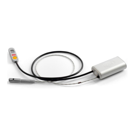
Page 5: Construction
The filter is placed between the cable penetrations on the top. The whole body is sealed watertight. On the identification label is the following information: • SN (serial number), unique production number • MFD (Manufacture Date), year and month of manufacture • m AAD, commercial designation • Made in Czech Republic and EU, country of origin • logo and other required markings for this type of a device... -
Page 6: Control Unit
2. Function 2.2.2 Control Unit The body of the control unit is made of stainless steel and is connected to the processing unit by a flexible cable. The control unit has a display for various icons, the control button and the label specifying the device version. The label also includes the units - meters or feet. If the label indicates „meter“, all of the entered and displayed altitudes are in meters. If the label indicates „feet“, all of the altitudes entered and displayed are in feet. -
Page 7: Function
The m was designed to be an extremely simple safety device to use. Most users just want to switch the AAD on before the first jump and no longer worry about it. In addition to the standard mode, which the user will use the most, the m software also enables other functional modes: a mode for landing above the aircraft’s take off, a mode for landing below the... -
Page 8: Standard-Mode
3. Function 3.2.1 STANDARD-mode The STANDARD-mode is used always when the skydiver starts and lands at the same location, same drop zone and doesn’t need to change the device parameters. Landing location is at the same elevation above sea level as the aircraft take-off location. The display shows the icon. When using this mode, always switch the device on at the landing location. The m device requires for the aircraft to ascend up to at least 40 m (130 ft) in order for correct start detection and to remain above this altitude until the skydiver’s jump. Further, depending on the device version, it is necessary to exceed the preset altitude lock by either 450 m (1,475 ft), or 900 m (2,950 ft) to unlock the device. +450 m / + 1,475 ft (+900 m/ +2,950 ft for Tandem) +40 m / + 130 ft Ground Restricted area... -
Page 9: Up-Mode
3. Function 3.2.2 UP-mode The UP-mode is used when the landing location is higher than the aircraft take-off location. The display shows the icon. When using this mode, switch the device on at the aircraft take-off location. For the correct functioning of the m , it is necessary to preset the elevation difference between the landing and take-off location altitu- de. The numeric value of how much higher the skydiver will land compared to aircraft take-off must be entered. In this case, the altitude lock depends on the landing location, i.e. as per version 450 m (1,475 ft) or 900 m (2,950 feet), plus the specified altitude difference. In such a case, the m device requires for the aircraft to immediately ascend up to at least 40m (130 ft) above the take-off location in order to allow correct start detection, and to remain above this alti- tude. Upon reaching and ex- +450 m / + 1,475 ft (+900 m/ +2,950 ft for Tandem) ceeding this preset altitude of plus 40 m (130 ft), the aircraft must remain above this alti-... -
Page 10: Down-Mode
3. Function 3.2.3 DOWN-mode The DOWN-mode is used when the landing location is lower than the aircraft take-off location. The display shows the icon. When using this mode, switch the device on at the aircraft take-off location. For the correct functioning of the m , it is necessary to preset the elevation difference between the altitude of the take-off and landing locations. The numeric value of how much lower the skydiver will land compared to aircraft take-off must be entered. In this case, the altitude lock depends on the landing location, i.e. as per version 450 m (1,475 ft) or 900 m (2,950 feet), minus the specified altitude difference. In such a case, the m device requires for the aircraft to immediately ascend up to at least 40 m (130 ft) above the take-off location in order to allow correct start detection, and to remain above this altitude for at least 90 seconds After 90 seconds, it is possible to descend even lower than the take-off altitude; nevertheless, you must not descend under the preset landing location altitude plus 40 m (130 ft). Upon landing with the preset altitude, the device automatically switches off. -
Page 11: X-Mode
3. Function 3.2.4 X-mode (Only for devices with firmware 2xxx and higher) X-mode is suitable for use when the take-off location and landing location (drop zone) are the same and a change in the device parameters is not needed. The function is the same as for the STANDARD-mode, what changes are the device parameters. The landing location is at the same elevation above sea level as the aircraft take-off location. The display shows the icon. When using this mode, always switch the device on at the landing location. Device parameters change as follows: STANDARD-mode X-mode... -
Page 12: Function Of M 2 At Use In A Pressurized Aircraft
3. Function Function of the m in a pressurized aircraft The m device can be used in pressurized aircraft providing the conditions below are observed. The ambient atmospheric pressure (outside the aircraft) must be maintained inside the aircraft up to 450 m (1,475 ft) above the aircraft take-off location for the m EXPERT, m STUDENT and m SPEED device versions and 900 m (2,950 ft) for the m TANDEM version. At the specified altitudes, the device will be unlocked, which will be indicated by the disappearance of the centre line on the control unit. Once the altitude lock unlocks, the aircraft can be pressurized. -
Page 13: Safety Device Versions
It is possible to reach a speed of 13m/s (29 mph) on a fully functional parachute!!! If the student does not jump from the aircraft and returns for the landing, always switch off the m2 STUDENT. If this is not possible, the aircraft must not descend faster than 13m/s (29 mph). -
Page 14: M 2 Tandem
4. Safety device versions TANDEM The m TANDEM version is designated for tandem gear. Activation occurs if the altitude above the landing area is below 610 m (2,000 ft) and the falling speed is over 35 m/s-1 (78 mph). The altitude lock is 900 m (2,950 ft). Activation will not occur under an altitude of 100 m (330 ft). Therefore, the activation zone is in the range between 610 m and 100 m (2,000 ft and 330 ft) above the landing location. TANDEM meter TANDEM feet SPEED The m SPEED version is designated for canopy piloting. This version is for the most experienced pilots with extremely fast pa- rachutes and with great experience! Activation occurs if the altitude above the landing area is below 270 m (885 ft) and the falling speed is over 45 m/s-1 (101 mph). The altitude lock is 450 m (1,475 ft). Activation will not occur under an altitude of 150 m (490 ft). - Page 15 4. Safety device versions TANDEM 900 m 2,950 ft 2,950 alt - lock 2,625 2,295 610 m 2,000 ft 1,970 >35 m/s >78 mph SPEED EXPERT STUDENT 1,640 450 m 1,475 ft 450 m 1,475 ft 450 m 1,475 ft alt - lock alt - lock alt - lock...
-
Page 16: Installation
The cables of the m safety device must be placed in a fixed order. The thin cable of the cutter is always first. If the set for placing the m2 is sewn in such way that upon inserting the m device body into the pocket, the thin cable of the cutter is lower than the thick cable, wind the cable clockwise from the front view (if it is sewn higher, wind the cable counter-clockwise). - Page 17 5. Installation The thick cable of the control unit is always second and must be placed Cable of Control Unit on the wound thin cable. If the m device body is placed in such a way that the thick cable is higher than the thin cable, wind the cable counter- clockwise from the front view. If the set and device are placed in the opposite direction, then it is the reverse.
- Page 18 5. Installation Cables must not be placed in the pocket for the device body and, at the risk of cable damage, must not be even partially under the device body. Elastic pouch with Processing Unit Control Unit The cutter and the control unit location must comply with the harness manufacturer’s manual so that in both cases at least minimum cable spacing is ensured.
-
Page 19: Control
6. Control Control Principals To switch the m to the STANDARD-mode, press the control unit button four short times. This also prevents accidental switching on or off. After the device is switched on, it remains functional for 14 hours, and then turns itself off, regardless of the situation it is in. When not using your parachute, we recommend manually switching the device off. This saves the battery. After the activation sequence is complete, the instrument performs a self-check and calibration of zero altitude. If a problem is detected, the device reports an error. If you are switching the m on into a mode where you need to specify the altitude, the UP-mode or DOWN-mode, the numerical value of the altitude is entered by the individual digits. Gradually enter the whole number from left to right, from highest to lowest denomination. The m provides all of the digits from „0“... -
Page 20: Switching Device Off
6. Control Switching the device off Quickly press the control button (2) on the control unit body (1). Upon the icon being displayed (3) immediately press the button for a second time; the icon will be displayed; immediately press the button for a third time; when the icon is displayed, press the button for the fourth time. No icon will be displayed. The device is now off. If the switching-off sequence has not been completed, device will remain in ON mode. -
Page 21: Switching Device To Down-Mode
6. Control and calibration – flashing icon . It will then display the uicon, notifying that the device is now preset for the higher landing altitude. If the height presetting sequence is not properly completed, the device will go back into the OFF mode. The accuracy of the entered value can be checked in the menu under the letter „c“ - Correction. Switching the device on into DOWN-mode If the landing location is lower than the take-off location, it is necessary to reset the device for the altitude difference in advance. The m allows for upward adjustments between 10 m to 990 m (10 to 2,990 ft). If your device is in the meter version, you will be entering three positions. If... -
Page 22: Switching Device To X-Mode
Information in the device memory - MENU MENU display description 6.7.1 The m retains information which is available to the user upon following the steps below. The following information can be found in the m2 memory. Opening altitude of the last jump (in meters, 4 digits = 0000 to 9999m) (in feet, 5 digits = 00000 to 99999 ft) The opening altitude will not appear if the falling speed is not exceeded during a jump, such as in hop & pop, static line opening, etc. - Page 23 6. Control If the m is switched into UP-mode or DOWN-mode, the entered preset altitude will show, otherwise, it will read zero. Remaining battery in % (2 digits = 0 to 99%); If the battery shows just 1%, as an example, do not worry, the battery still has enough reserve and you can use the device all day. 100% will be displayed only upon the first time the m2 is switched on by the manufacturer. If a flashing „b“ appears instead of arrows when switching on for calibration and the battery status is 0%, do not use the device!!! Device serial number (6 digits = XXXXXX); Device configuration and firmware version (6 digits = VUFFFF); V = version “1“ - EXPERT “2“ - STUDENT “3“ - TANDEM “4“ - SPEED U = units “A“ – device calibrated in meters “F“ – device calibrated in feet FFFF = firmware version Year and month of manufacture (6 digits = YYYYMM; Y = year, M = month); GRAVITY index of the last jump (3 digits = 0–99.9%);...
-
Page 24: Sequence To Display Menu
After a short moment, a icon will be displayed – immediately press the control button and successively the following icons will be displayed in the stated order (see chapter 6.4.1) . By clicking on one of them, the values saved in the m2 memory under the selected icon will be displayed. Example: Shortly press the control button (2) on the control unit body (1). The icon will be displayed, and next icon , immediately press the control button and successively the following icons will be displayed in the stated order... -
Page 25: Quickcard Switch-On Sequence
6. Control QuickCard switch-on sequence click eror X-mode click EXPERT SPEED STUDENT EXPERT click TANDEM click click X-mode DOWN-mode UP-mode self test & set ground zero click click click click click click click click landing will be on ground zero switch on input input... -
Page 26: Quickcard Switch-Off Sequence
6. Control QuickCard switch-off sequence d - last jump deploy altitude [4] 0000 - 9,999 m [5] 0000 - 99,999 ft click J - total jumps counter [5] 99,999 jumps) c - correction altitude for next jump [3] 0 - 999 m [4] 0 - 2,999 ft b - remaining battery capacity [2] 99 - 0 % click click... -
Page 27: Maintenance
7. Maintenance Cutter replacement If the m device has been activated, there are two ways in which the device can be again made functional: Performance of a device and cutter: complete the form included in the manual with a detailed description of the event (activation) and send the form, along with the entire m device, to the address of either the manufacturer, MarS a.s. -
Page 28: Filter Replacement
Remove the old plastic filter (6) with the use of a small screw driver or pliers. Insert the screw driver directly into the filter centre (6) and, regardless of filter damage, remove the old filter (6) by pulling it from the device body (4). Check the filter area (6) for any impurities and, if clean, completely insert a new filter (6). The filter (6) must be fully inserted – press firmly applying great pressure, until it is completely buried in the m2 device body (4). Only the entry filter tube exceeds the outline of the device body. Switch on the device and check its function. Dispose of the filter in common waste or with plastic recycling waste. Upon the m... -
Page 29: Yearly Inspection
7. Maintenance Yearly Inspection The manufacturer requests that inspection of the m device be performed at least once every calendar year, either by the user or a rigger. The user is always responsible for this inspection and it is up to them whether the required tasks are performed on their own or entrusted to someone else. We recommend an inspection be done during repackaging of the reserve parachute. Inspection Procedure: Visually inspect the device for any apparent mechanical damage, especially that there is no damage on the connection cables, filter, control unit and cutter. -
Page 30: Securing Closing Loop In Washer
8. Securing closing loop in washer Variation 1 Variation 2... -
Page 31: Error Reports
9. Error Reports Error reports will be displayed on the device with the „ERROR“ icon. If this icon appears on the display of the control unit, the m must not be used for diving until the defect-failure is resolved. In order to discover the type of error, proceed as follows: Quickly press the control button (2) on the control unit body (1). The display (2) will show the error number in the form of this example: . Digit 2 specifies the type of error-defect. If the „FAILURE“ icon appears on the display, the device will be disabled and it is not possible to switch it on or off. It must be sent to the manufacturer for service. -
Page 32: Technical Data
Upon reaching zero capacity, upon activation during calibration the device will display a flashing icon with the letter „b“ (battery), the device will still be functional. Never use the m2 device with 0% battery capacity!!! 10.3 Cutter Lifetime The total cutter lifetime is 16 years from the manufacture date. The cutter is marked with the year of manufacture and batch code. -
Page 33: Important Principles
11. Important principles • The device must be switched on at the GROUND ZERO landing location or at take-off location; never in an airplane or other airborne transportation. STUDENT and the m EXPERT, • The unit is functional (armed) upon the altitude lock release at a height of 450 m (1,475 ft) for the m or 900 m (2,950 ft) for the m TANDEM. The center line between the arrows on the display will disappear. • Airborne aircraft must not descend below the landing location altitude plus 40 m (130 ft), once it has already exceeded this altitude. • If a jump was abnormally long, more than 1.5 hours, switch the device off and on again. • If you land outside the airport, or if leaving the airport to later return, switch the device off during any transport, and back on again before the next jump. • If you accidentally land at a place situated approximately 30 m (100 ft) higher or lower than the selected landing area, switch the device off after landing and turn it back on before the next jump. • Maintain a safe altitude to open the main parachute. Avoid dropping into the activation zone. Avoid the risk of opening the reserve parachute along with the main one. -
Page 34: Warranty
12. Warranty All the parts used in the m device, and its total correct function as per the specified limits, are covered by the manufacturer’s 24-month warranty, valid from the date of purchase. The warranty does not cover damages occurring from common use of the m device, incorrect installation, or non-standard and rough handling. The manufacturer reserves the right to decide whether to repair or replace the unit. -
Page 35: X-Ray Card
13. X-RAY card To Airport Security Personnel: The device m is parachute emergency opening system for reserve parachute. The m is a life saving device for skydivers. Display on the screen (X-ray) may be different depending on the parachute container. All parts of device are not subject to any transport regulations. The m parts: 1. central unit, 2. control unit, 3. cutter, 4. control unit cable, 5. cutter cable X-ray card Packed in a box MarS a.s., Okruzni II 239 569 43 Jevicko, Czech Republic mars@marsjev.cz... -
Page 36: Disclaimer
The safety device (AAD) is an electronic device and, like any other electronic device, may not always work properly, even providing that it is properly installed and used. Using the appliance only reduces the risk of injury or even the death of the user. Should the user still choose to use the device or put the unit at the disposal of another person to use, this act confirms they are aware of these risks and the potential consequences associated with the use of the device.
Need help?
Do you have a question about the AAD and is the answer not in the manual?
Questions and answers