Table of Contents
Advertisement
Quick Links
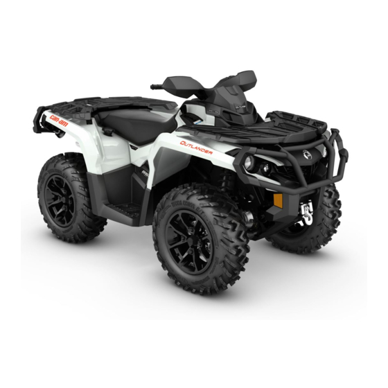
2017
T3 4x4 OUTLANDER
/
TM
OUTLANDER
MAX
TM
TM
570/650/1000 Series
WARNING
Read this guide thoroughly. It contains important safety information.
Minimum recommended age: Operator: 16 years old. Driving tractor requires at least a tractor
driving license. Keep this Operator's Guide in the vehicle.
2 1 9
0 0 1
7 7 0
Original Instructions
Original Instructions
Advertisement
Table of Contents
Troubleshooting


Need help?
Do you have a question about the 570 Series and is the answer not in the manual?
Questions and answers
How to check engine hours
To check engine hours on a Can-Am 570 Series, look at the Main Digital Display or the Secondary Digital Display. These displays show real-time information such as engine hours. Use the MODE (M) button to cycle through display options until engine hours are shown.
This answer is automatically generated