Table of Contents
Advertisement
Quick Links
Advertisement
Table of Contents

Related Manuals for Johnson Controls SABROE SAB 273


Summary of Contents for Johnson Controls SABROE SAB 273
- Page 1 Operating manual SAB 273 High-pressure screw compressor...
- Page 3 Manual for SAB 273 high-pressure screw compressor Unit no. Compressor Compressor type Bearing configuration HPSS HPSD Oil separator type OHU 5040/4040 Vi range 1.3-1.96 1.7-3.0 2.2-5.0 Refrigerant R717 Oil type Oil type: _________________ Evap. temp. _____ Cond. temp. _____ Control UniSAB None Other...
- Page 4 Vessel data Design pressure External surface Type [bar] Condenser Evaporator Liquid separator Oil separator Safety valve: Data for calculation of Oil cooler downstream line accord- ing to EN 13136 Economiser Other Pressure loss, if any, from safety valve to customer connection (based on design pressure) [bar] _____________ Safety valve type: Back-pressure dependent...
-
Page 5: Table Of Contents
Contents Introduction to the operating manual ............7 Compressor name, Sabroe/Frick ...........7 Safety precaution definitions used in this manual ......9 Requirements for competent persons ..........9 Areas of application ................10 Application of the screw compressor ........... 10 Application of combustion engines ..........10 Identification .................. - Page 6 Compressor oil separation system ..........32 6.10 Automatic oil return valve ............34 6.11 Compressor hydraulic system ............. 35 6.12 Volume ratio (VI) control ............. 36 6.13 Compressor oil cooling systems ..........37 6.14 Equalisation ................37 6.15 Balance piston pressure regulator ..........37 6.16 Low ambient temperature operation ..........
-
Page 7: Introduction To The Operating Manual
SAB 273 S Compressor name, Sabroe/Frick The compressor in a Sabroe SAB 273 screw compressor unit is manufactured by Frick. Below is indicated how the Sabroe and Frick compressor names are made up and how they corre- spond to each other. - Page 8 Copyright © Johnson Controls Denmark ApS This manual must not be copied without the written permission of Johnson Controls Denmark, and the contents must not be imparted to a third party nor be used for any unauthorised purpo- ses. Contravention will be prosecuted.
-
Page 9: Safety Precaution Definitions Used In This Manual
Introduction to the operating manual Safety precaution definitions used in this manual Danger! Indicates an imminently hazardous situation which, if not avoided, will result in death or serious injury. Warning! Indicates a potentially hazardous situation or practice which, if not avoided, will result in death or serious injury. -
Page 10: Areas Of Application
Warning! Johnson Controls Denmark is not liable for injuries to personnel or damage to equipment re- sulting from using the equipment for other purposes than the ones stated above. Operating manual - SAB 273 High-pressure screw compressor 10/56 0015821 en 2023.03... -
Page 11: Identification
Identification 3. Identification Identification All Johnson Controls Denmark equipment can be identified by one or several name plates as il- lustrated in the following. Operating manual - SAB 273 High-pressure screw compressor 0015821 en 2023.03 11/56... -
Page 12: Unit/Pipe System Name Plate
Identification Unit/pipe system name plate Johnson Controls Denmark ApS 1000010127 1000010126 Johnson Controls Denmark ApS Christian X's Vej 201 Christian X's Vej 201 8270 Højbjerg, Denmark 8270 Højbjerg, Denmark MADE IN DENMARK MADE IN DENMARK www.sabroe.com www.sabroe.com Serial Serial Year... - Page 13 Identification The unit name plate is positioned on the frame and contains this information: Unique identification number. Serial No. Year of manufacturing. Year Type Manufacturer's type designation. For EC PED/EAC approval: ‘Unit & Piping’ means that the CE/ EAC mark applies to the complete unit including the piping sys- tem.
-
Page 14: Compressor Name Plate
Identification Compressor name plate Fig. 5: Compressor name plate Fig. 6: Refrigerant plates Note: The compressor is fitted with a name plate, Fig. 5, and one of the two refrigerant name plates shown in Fig. 6. The rotary screw compressor serial numbers contain the following information: Example: 10240A90000015Z. -
Page 15: Geometrical Swept Volume
Identification Geometrical swept volume Geometrical Min. Max. Screw Rotor swept volume Speed Speed compr. Rotor drive shaft end dia. 2950 rpm unit /Rev. /Rev. HPS 2709 1,000 3,600 0.27428 0.007767 1375 HPS 2712 1,000 3,600 0.36570 0.010355 1833 Table 2: Geometrical swept volume Operating manual - SAB 273 High-pressure screw compressor 0015821 en 2023.03 15/56... -
Page 16: Vessel Name Plate
Allowable temperature, TS has been designed for. © Copyright - Johnson Controls Denmark ApS - All rights reserved. PROPRIE The volume of the vessel or vessel part. Volume The CE mark appears on the name plate for EC PED approval. -
Page 17: Safety Precautions
Safety precautions 4. Safety precautions Signs All signs which may be found on your equipment are shown below. The number of signs, how- ever, may vary from one product to another. High surface High voltage/ The compressor may be top- temperature Risk of electric shock heavy... -
Page 18: During Operation
Safety precautions General Use these precautions as a supplement to the safety precautions and warnings included in: • All other manuals pertaining to the compressor/unit. • Local, plant and shop safety rules and codes. • National safety rules and regulations. Read and understand all safety instructions before setting up, operating or servicing/perform- ing maintenance on the compressor. -
Page 19: Safety During Maintenance And Service
Use the prescribed tools, and check that they are properly maintained and in good working condition. In explosion-proof areas, use tools suited for this specific purpose. • Use only Johnson Controls Denmark original spare parts; other parts may impair the safety of the compressor/unit. •... -
Page 20: Purging A Refrigeration Plant
Safety precautions Code design Oil types Mineral oil, naphtenic base Synthetic oils based on alkylated aromatics (alkyl-benzene) Synthetic oils blended from alkyl-benzene and poly-alfa-olefin base stocks Semi synthetic oils (hydro-treated mineral oil on paraffinic base) Synthetic oils based on poly-alfa-olefin Synthetic oils based on polyol esters Synthetic oils based on polyalkylene glycols See the Sabroe oil recommendation for the recommended type of oil. -
Page 21: F-Gas Regulation (Fluorinated Greenhouse Gases)
Safety precautions F-gas regulation (fluorinated greenhouse gases) In the European F-gas regulation, No 517/2014, about reduction of harmful gases in the at- mosphere, the European Parliament (EU) has established guidelines for the regulation of cer- tain fluorinated greenhouse gases. The following is an extract from the guidelines and is relevant for end users and operators. - Page 22 Safety precautions The equipment must be checked for leakage within one month after a leak has been repaired to ensure that the repair has been effective. Recovery of refrigerant Operators are responsible for putting in place arrangements for the proper recovery of fluori- nated greenhouse gases by competent personnel to ensure recycling, reclamation or destruction.
-
Page 23: Sound Measurement And Noise Data
For 60 Hz-driven compressors, add + 2 dBA to the stated levels. Type of unit SAB 273 S Table 3: Noise data Noise data for other operating conditions can be provided by Johnson Controls Denmark on request. Note: • The actual SPL value on site will be between the stated SPL and SWL depending on the acoustic environment in the machine room. -
Page 24: Installation
Installation 5. Installation Installation in terms of mechanical work (refrigeration system and piping), electrical work and installation of safety equipment must be performed in accordance with local codes/rules and/or according to EN 378-3 and EN 378-4 as a minimum requirement. The pressure loss in the downstream line from the safety valve must meet the values stated in EN 13136 to which EN 378 is referring. -
Page 25: Operating Instructions
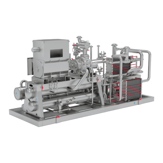
Operating instructions uctures 6. Operating instructions s apply erwise mensions Read chapter 4. Safety precautions carefully before operating the unit. mm/m Description of the unit 0 45' 0 30' 0 20' Control system The compressor unit is controlled by an electronic control system. The control system is de- scribed in a separate manual, delivered with the unit. - Page 26 Operating instructions Fig. 10: SAB 273 unit with oil separator OHU 5040/4040 seen from the back. Tolerances apply Tolerances apply unless otherwise unless otherwise specified for specified for angular dimensions linear dimensions Length l of the shorter up to 6 side of the Over 6 angle...
-
Page 27: General Piping Diagram
Operating instructions General piping diagram Fig. 11: General piping diagram - SAB 273 with OHU 5040/4040 oil separator is shown here. Operating manual - SAB 273 High-pressure screw compressor 0015821 en 2023.03 27/56... - Page 28 Operating instructions Legend (Covers all P&I diagrams in this manual) Air Supply Pump Motor Compressor Pressure cut-out Check valve PZHH Safety Pressure cut-out Discharge pressure High Pressure Safety Valve Filter or Filter Drier Resistence Temp Detector Flow Glass Suction Pressure High Oil Level Switch Strainer Heater...
-
Page 29: Valve Positions During Operation
Operating instructions Valve positions during operation Designation In-operation position Pos. no. Suction stop valve Open Stop valve after oil separator Open Open to safety valve, Change over valve no. 1 or no. 2 Safety relief valve (Closed) Fixed set point 104/PSV1 Safety relief valve (Closed) Fixed set point... -
Page 30: Descriptions Of Main Components And Systems
Operating instructions Designation In-operation position Pos. no. Compressor Electric motor Oil separator Oil filter Oil filter Stop valves - oil return Open Automatic oil return Non-return valve Level glass Oil drain stop valve coalescer bleed Closed In-line filter Oil drain stop valve coalescer bleed Closed Oil pressure before SB-2 Motor valve... -
Page 31: Compressor Lubrication System
Operating instructions – 2.2 Vi to 5.0 Vi – 1.7 Vi to 3.0 Vi – 1.3 Vi to 1.96 Vi • High capacity roller bearings to carry radial loads are used at both inlet and outlet ends of the compressor. •... -
Page 32: Prelubrication And Start-Up Oil Pump
Operating instructions A shaft seal is mounted at the shaft end (driving shaft) of the male rotor. The shaft seal ensures complete tightness between the compressor housing and the compressor shaft, thus prevent- ing atmospheric air from entering the compressor. Prelubrication and start-up oil pump The screw compressor unit is designed to be self-lubricating during operation. - Page 33 Operating instructions To coalescer To coalescer To oil reservoir From compressor To oil reservoir Fig. 13: OHU 5040/4040 Discharge gas to condenser Coalescer Demister Oil return Oil return To oil reservoir To oil reservoir From compressor Fig. 14: Principle for OHU 5040/4040 Note: Automatic oil return: Open the service valves completely to keep the coalescer end of the separator free of oil.
-
Page 34: Automatic Oil Return Valve
Operating instructions 6.10 Automatic oil return valve 1: Inlet G1/4” 4: Stop valve, outlet side 2: Filter 5: Outlet G1/4” 3: Stop valve, inlet side 6: Sight glass Fig. 15 Note: Valve inlet and outlet are marked on the valve housing with "in" and “out”. Function The function of the automatic oil return valve, EVRB, is to return the separated oil in the fine separator to the compressor. -
Page 35: Compressor Hydraulic System
Operating instructions Fig. 16 Note: The sectional view shows the valve structure. Some of the internal oil channels are not visible. 6.11 Compressor hydraulic system The compressor hydraulic system actuates the movable slide valve (SV) to load and unload the compressor, which affects the compressor’s capacity. It also actuates the moveable slide stop (SS) to increase or decrease the compressor’s VI, which determines the compressor’s compression ratio. -
Page 36: Volume Ratio (Vi) Control
Operating instructions • Open valve at SC1 • Close valve at SC2 • Open valve at BP (bypass). Compressor loading (single acting) The compressor loads when SV solenoid YY2 is energised and oil flows from the unload side of the cylinder out of port SC1, through valve ports A and T to the compressor suction side. Si- multaneously, discharge pressure loads the slide valve. -
Page 37: Compressor Oil Cooling Systems
Operating instructions 6.13 Compressor oil cooling systems Compressor oil needs to be cooled to control the discharge temperature, maintain correct oil viscosity and to preserve the life of the oil. The discharge temperature depends on application and operation conditions. The unit can be equipped with water-cooled or refrigerant-cooled (thermosyphon) oil coolers. -
Page 38: Heating Element
Operating instructions 6.17 Heating element To keep the compressor lubricating oil warm during a period of standstill, two heating elements are built into the oil reservoir. Before start-up, the heating elements must be switched on for 6- 8 hours to ensure that only a minimum of refrigerant remains in the oil. If there is too much re- frigerant in the oil, the oil loses its lubricating properties. - Page 39 Operating instructions application. The adjustment at first start-up is made via the UniSAB III display - and not on the valve motor’s control display (ICAD). Correct setting at first start-up: when the unit has achieved nominal operating conditions, adjust the parameter called Oil Flow Open Max. via the UniSAB III display. Increase the value if the discharge temperature is too warm and decrease it if the temperature is too cold.
-
Page 40: Stopping Routine
Operating instructions 6.20 Stopping routine Brief stop The compressor can be stopped at any capacity setting. However, under normal conditions it is recommended to reduce the capacity to a minimum before stopping the compressor. Leave all valves in their “in-operation positions”. Do not turn off the power to the screw com- pressor unit as the oil heater must be connected to keep the correct oil temperature. -
Page 41: Troubleshooting
Troubleshooting 7. Troubleshooting The tables below cover the most common problems. For detailed troubleshooting of the refrig- eration plant, please refer to the manual of the plant or common refrigeration literature. Refrigeration plant, general issues Symptom Probable cause Solution Refrigeration load lower than com- Reduce compressor capacity. - Page 42 Troubleshooting Compressor unit, general issues Symptom Probable cause Solution Check main switch and fuses. Re- Electrical supply. set emergency stop switch, etc. Register the alarm, correct if neces- Compressor cannot Alarm in control system. sary and reset (refer to the Control start manual).
- Page 43 Troubleshooting Compressor unit - oil separation Symptom Probable cause Solution Lower level by opening/adjusting Maintaining too high oil level. the oil return valve. Refrigerant carry-over or liquid in- Correct operation. jection overfeeding. Gradual oil loss with an oil level in the co- Loss of suction superheat.
- Page 44 Troubleshooting Compressor block Symptom Probable cause Solution Main oil injection valve may be Open valve. closed. Main oil injection valve may be Adjust. open too far. Bearing damage or excessive wear. Replace bearings. Excessive noise Slide valve/slide stop out of calibra- Calibrate.
- Page 45 Troubleshooting Demand oil pump system (optional) Symptom Probable cause Solution Pump rotation. Check. Open valve. Service valves closed. Check pressure difference across Filter cartridges may be blocked. Pump will not pro- filters. Strainer may be blocked. duce enough oil Clean strainer. pressure to start Oil pressure regulator set too low or Readjust or repair.
-
Page 46: Maintenance Instructions
Motor lubrication and other routine maintenance tasks are usually based on running time. Please refer to 8.2: Maintenance intervals . Major overhaul For major maintenance tasks such as compressor overhauls, contact Johnson Controls Denmark. Operating manual - SAB 273 High-pressure screw compressor 46/56 0015821 en 2023.03... -
Page 47: Maintenance Intervals
Maintenance instructions Maintenance intervals Table 10: Maintenance intervals Operating manual - SAB 273 High-pressure screw compressor 0015821 en 2023.03 47/56... -
Page 48: Monitoring Of Operation
Maintenance instructions Discharge flange to Suction flange separator flange 8” Class 600 Compressor 6” Class 600 designation model Bolt size Torque Bolt size Torque (Nm) (Nm) SAB 273 S HPS 2709 1” 1 1/8” SAB 273 L HPS 2712 1” 1 1/8”... - Page 49 Maintenance instructions Fig. 19: The checklist, which MUST be filled in during commissioning and start-up. Operating manual - SAB 273 High-pressure screw compressor 0015821 en 2023.03 49/56...
-
Page 50: Oil
We advise you to contact your local Johnson Controls representative about oil change as it is recommended to replace all filters in the unit at the same time. Local contact details are avail- able on www.sabroe.com. - Page 51 Maintenance instructions Place the free end of the suction hose from the pump, pos. 1, together with the by-pass hose, pos. 2, in the barrel. Open the ball valve, pos. 9, and service valve, pos. 106, and start the pump, pos. 5. Circulate the oil until the system is free from air bubbles.
-
Page 52: Motor
Please refer to the motor manual and/or the motor name plate. Replacing motor bearings Please contact your local Johnson Controls service organisation. Operating manual - SAB 273 High-pressure screw compressor 52/56 0015821 en 2023.03... -
Page 53: Final Disposal
Final disposal 9. Final disposal Safety precautions Danger! Before dismantling the plant, read the safety precautions carefully. Dismantling a refrigeration unit to be scrapped must be carried out safely. Only competent refrigeration personnel must perform the dismantling as fundamental knowl- edge of refrigeration systems and the risks involved are required. -
Page 54: Compliance
10.1 Declaration of conformity Johnson Controls Denmark declares on the signed declaration of conformity that the unit is manufactured and CE-marked in conformity with relevant directives and standards. The printed version of this operating manual, which is delivered with the unit, contains a trans- lated version of the declaration, however not filled in with the specific data for your unit. -
Page 55: Index
Index Batteries ............................. Charging compressor......................... Combustion engines - application....................Competent persons - requirements ..................... Compressor..........................Compressor hydraulic system....................Compressor lubrication system....................Compressor name explanation ....................Compressor name plate......................Compressor oil separation system..................... Compressor VI increase......................Cooling water system......................... Declaration of conformity ......................Demand pump oil system...................... - Page 56 Maintenance intervals ........................ Maintenance of compressor unit....................Monitoring of operation ......................Motor lubrication......................... Noise data ..........................Normal start-up procedure ......................Oil ............................... Oil cooling systems - compressor ....................Oil injection valve ........................Oil return valve ........................... Oil types............................Piping diagram ........................... Power supply..........................
- Page 58 Johnson Controls Denmark ApS Sabroe Factory Christian X's Vej 201 ∙ 8270 Højbjerg Denmark Phone +45 87 36 70 00 www.sabroe.com Version 1...
Need help?
Do you have a question about the SABROE SAB 273 and is the answer not in the manual?
Questions and answers