
Related Manuals for nilan Comfort 250 Top


Summary of Contents for nilan Comfort 250 Top
- Page 1 INSTALLATION INSTRUCTIONS CTS400 BY NILAN Comfort 250 Top Version 1.00 - 26.05.2021 M75 Comfort 250 Top GB...
-
Page 2: Table Of Contents
Fire Connection Box ....................................9 Vibration absorbers ..................................... 9 Flexible sound damper ..................................9 Pollen filter ......................................9 Cooker hood filter box ..................................9 Nilan User App ....................................10 Installation Placement ........................................11 Positioning of the ventilation unit ..............................11 Top unit ........................................ 11 Mounting the ventilation unit ................................ - Page 3 Ventilation installation Duct system ....................................... 30 Legislation ......................................30 Ducts ........................................30 Ventilation unit ....................................30 Extract air ......................................31 Supply air ......................................31 Roof terminals ..................................... 31 Installation example ...................................31 Balancing ........................................32 Important information ..................................32...
-
Page 4: General Information
The instructions can be downloaded from www.nilan.dk. If you have questions regarding installation and operation of the unit after having read the instructions, please contact your nearest Nilan dealer. A list of Nilan dealers is available on www.nilan.dk. ATTENTION The unit must be started up immediately after installation and connection to the duct system. -
Page 5: Unit Type
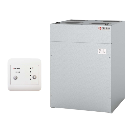
250 m Comfort 250 Top is a system with compact dimensions that can be built into a cabinet with a width of 60 cm. The control panel is built into the front of the unit, so no further installation is required. -
Page 6: Dimensional Drawing
Dimensional drawing All listed measurements are in mm. Right version: Left version: Connections: 1. Outdoor air 2. Supply air 3. Extract air 4. Discharge air 5. Condensate drain... -
Page 7: Functional Block Diagram
Functional block diagram Connections 1. Outdoor air 2. Supply air 3. Extract air 4. Discharge air 5. Condensate drain T1 /T8 6. Electrical and water after-heating element con- nections Automatic T2/T7: Supply air temperature sensors T3: Extract air temperature sensor T4: Discharge and de-icing temperature sensor T1/T8: Outdoor air temperature sensor T9: After-heating element temperature sensor... -
Page 8: Accessories
Accessories Electrical pre-heating element for frost protection of the unit If your ventilation unit is not a Polar version with an integral pre-heating element, we recommend that you purchase an external pre-heating element as frost protection of the ventilation unit. During prolonged periods of frost, the high efficiency counterflow heat exchanger will ice up. -
Page 9: Cts400 Connection Box
Fire Connection Box The Comfort ventilation unit has a function in its control system that can control 1-2 fire dampers. If you want to activate this function, Nilan can supply you with a Fire Connection Box, with the following connection options: •... -
Page 10: Nilan User App
You can control your ventilation unit with a smartphone app via a gateway connection. Connect the Nilan Gateway to a CTS400 or a CTS602 control system. This way, a cloud connection to the unit can be established. The Gateway is available in two different versions - with either a LAN or a WiFi connection... -
Page 11: Installation
Installation Placement Positioning of the ventilation unit ATTENTON When positioning the unit, you should always consider future service and maintenance. It must be easy to replace filters, and it must be possible to remove, for instance, the exchanger, and to replace fans or other components. -
Page 12: Duct Connections
Duct connections It is possible to connect the duct pipe directly to the spout. If necessary use a duct connector (not Nilan delivery). 1. Use a Ø160mm duct connector. 2. Press the duct connector well into the ventilation spout. -
Page 13: Electrical Installation
Electrical installation Electrical connections Safety ATTENTION All work must be carried out by qualified persons and in compliance with existing legislation and regulations. ATTENTION It is important that the power is off, if you do work to the electrical components of the unit. It is important to check that wires are not damaged or squeezed during connection and use. -
Page 14: Electrical Connections Accessories
Electrical connections accessories Overview of connection options You can connect external accessories to the ventilation unit. However, it is not possible to have all accessories connected up simulta- neously. The following table shows the external connections that are possible in the different settings. Setting User selection 1 User selection 2 /... -
Page 15: Overview Of Connection Boxes
Overview of connection boxes You can connect up external connections via 4 connection boxes, depending on which settings you have selected in the Software. Normal setting A CTS400 Connection Box allows you to connect up the following functions: Brown User selection output 500 mm Brown/white Fire thermostat/external fire automation system... -
Page 16: User Selection 1 And 2 (Cooker Hood)
User selection 1 and 2 (cooker hood) If the fire automation system has not been activated in the software, you will have access to both User selection 1 and User selection 2. ATTENTION If the fire automation system has been activated, you will only have access to User selection 1. The user selection functions are used to override standard operation. -
Page 17: Joint Alarm
Joint alarm It may be difficult to notice alarms if the unit is located in a place where access is difficult or infrequent, and if the control panel is locat- ed in the same place. An external alarm indicator in the form of an electric bulb or an acoustic signal can be connected to the ventilation unit and announce when an alarm occurs. -
Page 18: Em-Box (Damper Solution)
EM-box (damper solution) If you want to run the cooker hood via the ventilation unit, you may find the air volume to be insufficient for cooker hood extraction. ATTENTION The EM-box solution cannot be used if the fire automation system has been activated in the software. If you install an EM-box, you can regulate the extract air when the cooker hood is on, so that less air is drawn from, for instance, the bathroom and the utility room. -
Page 19: Dtbu Damper Solution
DTBU damper solution If you want to run the cooker hood via the ventilation unit, in some cases there may be insufficient air for cooker hood extraction. DTBU-spjæld løsningen kan ikke anvendes, hvis brandautomatikken er aktiveret i softwaren. An EM-box solution can solve this. However, if there is insufficient space in the installation for an EM-box, the alternative may by to connect up a DTBU damper in the duct system. -
Page 20: External Pre-Heating Element
External pre-heating element It is possible to purchase an external electric pre-heating element for frost protection of the ventilation unit. The electric preheating element is mounted in the outdoor air duct before the unit with the necessary temperature sensor. If it is desired to see the actual outdoor air temperature on the control panel, the temperature sensor T1 / T8 must be led out into the duct before the preheating surface. -
Page 21: Electrical After-Heating Element
Electrical after-heating element An after-heating element is necessary if you want to control the supply air temperature. The electric after-heating element can be purchased for installation in the supply air duct and the necessary sensor, connection box and connection to the ventilation unit are included. The wire from the heating element to the connection box (A) is 2 meters long and from the box to the RJ45 plug there is 0.5 meter. -
Page 22: Water After-Heating Element
Water after-heating element An after-heating element is necessary if you want to control the supply air temperature. The water after-heating element can be purchased for installation in the supply air duct and the necessary sensor, connection box and connection to the ventilation unit are included. The wire from the heating element to the connection box (A) is 2 meters long and from the box to the RJ45 plug there is 0.5 meter. -
Page 23: Plumbing Installation
Plumbing installation Condensate drain Connection of water trap It is important that the water trap complies with the measurements below. If the water trap is placed outside the climate screen, it should be protected against frost. Ø20 mm min. 50 mm min. -
Page 24: Plumbing Connection Accessories
2. Actuator and regulation valve Supply Danfoss AME 140/24V 0-10V signal, 2-way valve flow VZ2 Kv 0.4 (Nilan supply) the Kvs value must be checked against the power supply. Differential pressure: 0.1 - 0.6 bar. With a flow temperature of 60°C and at maximum heat output, the temperature is estimated to fall with 20°C over the heating element... -
Page 25: Fire Automation System
It is important to check that wires are not damaged or squeezed during connection and use. Usage Nilan's fire automation system is used to monitor, test and check the fire protection components of the ventilation system: • Fire and smoke damper, and fire thermostat Important functions: •... -
Page 26: Electrical Connection Fire Automation System
Electrical connection fire automation system Connection of fire damper As an optional extra you can purchase Nilan's Fire Connection Box for connection of fire dampers. The fire automation system is integrated into the control system. Belimo fire damper Connection to the wiring harness 24 /230V AC... -
Page 27: Connecting Two Fire Dampers
Note that the two extra wires from dampers (S3 and S5) are not used. Connect the supply voltage from Neutral and relay 5 in a parallel circuit. Mount junctions in an external junction box (not supplied by Nilan) Connect up S1-S6 to Nilan’s fire automation box as shown under “Connecting fire dampers” Fire damper 1 Fire damper 2... -
Page 28: Alarm Code
Alarm code Set an alarm 96 - "Damper test" if a position (open / closed) has not been fulfilled within the maximum moving time of 120 seconds. The test will fail if: • Current starting position (open) is incorrect • Current position (open and closed) has not altered within the first 12 seconds of moving in each direction •... -
Page 29: Schedule For Functional Testing
Schedule for functional testing ATTENTION DS428 requires written documentation of the annual test of the fire automatic system. Date: Comments: Tested by:... - Page 30 This is to avoid vibrations from the unit being transmitted to the duct system. It will also make it easier to move the unit, which may be necessary during future services of the unit. Nilan can supply Soundflex tubes that you can use as flexible connections between the ventilation unit and the duct system. They will also reduce sounds from the system considerably.
- Page 31 Extract air Install the extract air valves in high-humidity rooms and place them strategically where they can extract humid and vitiated air from the dwelling/building most efficiently. High-humidity rooms are, for example: • Bathroom • Lavatory • Kitchen • Utility room Supply air Install supply air valves in living areas.
- Page 32 Balancing Important information ATTENTION To ensure the ventilation system operates optimally, it is important that it is balanced correctly. We recommend that experts do this. It is important to measure the total supply air and the total extract air. The system must have a minimum vacuum, which means it draw out more air than it blows in.
- Page 36 25 St Leonards Road Horsham West Sussex RH13 6EH Tel: +44 (0) 14 03 56 30 45 service@slservicesgroup.com or info@slservicesgroup.com www.slservicesgroup.com Ireland: Nilan Ireland Ballylahive, Abbeydorney Tel: +353 (0) 87 97 98 361 maurice@nilan.ie www.nilanireland.ei Nilan A/S Nilanvej 2 8722 Hedensted Danmark Tlf.
Need help?
Do you have a question about the Comfort 250 Top and is the answer not in the manual?
Questions and answers